EP1528349B1 - Verfahren zur Herstellung einer Wärmetauschervorrichtung - Google Patents
Verfahren zur Herstellung einer Wärmetauschervorrichtung Download PDFInfo
- Publication number
- EP1528349B1 EP1528349B1 EP04025179A EP04025179A EP1528349B1 EP 1528349 B1 EP1528349 B1 EP 1528349B1 EP 04025179 A EP04025179 A EP 04025179A EP 04025179 A EP04025179 A EP 04025179A EP 1528349 B1 EP1528349 B1 EP 1528349B1
- Authority
- EP
- European Patent Office
- Prior art keywords
- hollow tube
- heat
- connecting pipe
- porous core
- evaporator
- Prior art date
- Legal status (The legal status is an assumption and is not a legal conclusion. Google has not performed a legal analysis and makes no representation as to the accuracy of the status listed.)
- Expired - Lifetime
Links
- 238000012546 transfer Methods 0.000 title claims abstract description 30
- 238000004519 manufacturing process Methods 0.000 title claims abstract description 21
- 238000000034 method Methods 0.000 title claims description 17
- 239000004020 conductor Substances 0.000 claims abstract description 28
- 239000012530 fluid Substances 0.000 claims abstract description 25
- 238000003466 welding Methods 0.000 claims description 12
- 238000004080 punching Methods 0.000 claims description 8
- 238000004891 communication Methods 0.000 claims description 3
- 238000007789 sealing Methods 0.000 claims description 3
- 238000010438 heat treatment Methods 0.000 abstract description 15
- 239000002184 metal Substances 0.000 description 9
- 239000007788 liquid Substances 0.000 description 5
- 238000005516 engineering process Methods 0.000 description 3
- 238000001816 cooling Methods 0.000 description 2
- 238000010276 construction Methods 0.000 description 1
- 238000007796 conventional method Methods 0.000 description 1
- 230000007812 deficiency Effects 0.000 description 1
- 238000013461 design Methods 0.000 description 1
- 230000005484 gravity Effects 0.000 description 1
- 230000017525 heat dissipation Effects 0.000 description 1
- 238000012986 modification Methods 0.000 description 1
- 230000004048 modification Effects 0.000 description 1
- 238000003825 pressing Methods 0.000 description 1
- 230000009466 transformation Effects 0.000 description 1
Images




Classifications
-
- F—MECHANICAL ENGINEERING; LIGHTING; HEATING; WEAPONS; BLASTING
- F28—HEAT EXCHANGE IN GENERAL
- F28D—HEAT-EXCHANGE APPARATUS, NOT PROVIDED FOR IN ANOTHER SUBCLASS, IN WHICH THE HEAT-EXCHANGE MEDIA DO NOT COME INTO DIRECT CONTACT
- F28D15/00—Heat-exchange apparatus with the intermediate heat-transfer medium in closed tubes passing into or through the conduit walls ; Heat-exchange apparatus employing intermediate heat-transfer medium or bodies
- F28D15/02—Heat-exchange apparatus with the intermediate heat-transfer medium in closed tubes passing into or through the conduit walls ; Heat-exchange apparatus employing intermediate heat-transfer medium or bodies in which the medium condenses and evaporates, e.g. heat pipes
- F28D15/04—Heat-exchange apparatus with the intermediate heat-transfer medium in closed tubes passing into or through the conduit walls ; Heat-exchange apparatus employing intermediate heat-transfer medium or bodies in which the medium condenses and evaporates, e.g. heat pipes with tubes having a capillary structure
- F28D15/043—Heat-exchange apparatus with the intermediate heat-transfer medium in closed tubes passing into or through the conduit walls ; Heat-exchange apparatus employing intermediate heat-transfer medium or bodies in which the medium condenses and evaporates, e.g. heat pipes with tubes having a capillary structure forming loops, e.g. capillary pumped loops
Definitions
- This invention generally relates to a method thereof, and more particularly to a heat transfer device and manufacturing method of a heat transfer device to simplify the manufacturing process, reduce costs, and enhance heat conductivity.
- a radiator will be disposed on the heating element of the electronic device provide a larger area for heat dissipation.
- a cooling fan will be used to provide a cool air current to further dissipate the heat.
- the electronic device can keep within the range of the operational temperature.
- the radiator and the cooling fan are used in the CPU, North Bridge, and graphic chip of the personal computer, which can generate high heat.
- FIG. 1 is a conventional heat transfer device.
- the conventional heat transfer device 100 comprises a evaporator 110, a loop heat pipe 120, and a condenser 130.
- the evaporator 110 comprises a metal tube 112 and a porous core 114.
- the porous core 114 is disposed inside the metal tube 112.
- the evaporator 110 is disposed on the heating device such as CPU.
- the loop heat pipe 120 is connected to the evaporator 110 and has a proper amount of working fluid therein.
- the condenser 130 is disposed on the loop heat pipe 120 to condense the steam in the loop heat pipe to the liquid state.
- the evaporator 110 When the heating device generates high heat, the evaporator 110 will receives the heat and thus the working fluid in the porous core 114 will be heated up and enter into the loop heat pipe 120 and the condenser 130. The condenser 130 then condenses the steam in the loop heat pipe to the liquid state. The capillarity attraction of the porous core 114 will attract the working fluid in the loop heat pipe 120 back to the evaporator 110 and the porous core 114 therein. Hence, this design form a loop so that the working fluid can flow circularly in the loop heat pipe 120 and transfer the heat generated by the heating device to the condenser 130.
- FIGs. 2A - 2C show the manufacturing process of the conventional heat transfer device.
- the manufacturing method of the conventional heat transfer device 100 directly fuses a porous core 114 inside a hollow metal tube 112 (as shown in FIG. 2A ).
- the two caps 140 are welded at the two ends of the hollow metal tube 112 (as shown in FIG. 2B ).
- the loop heat pipe 120 is welded on the caps 140.
- a heat conducting platform 150 is welded at the bottom if the hollow metal tube 112 so that the high heat of the heating device 10 can be transferred from the heat conducting platform 150 to the evaporator 110 (as shown in FIG. 2C ).
- the manufacturing method of the conventional heat transfer device has the following disadvantages:
- the porous core is directly fused inside the hollow metal tube, which is costly and very difficult to implement and to control the quality.
- the heat conducting platform can only conduct the heat to the lower part of the evaporator. Hence the heat conductance is too low.
- US Patent Publication No. 2003/0178184 also describes an evaporator of a heat transfer device that includes a first hollow tube, a porous core inserted in the first hollow tube through one open end thereof, and a second hollow tube having one open end formed contiguous with the one open end of the first hollow tube.
- a connecting pipe is disposed in fluid communication with the other end of each of the tubes and and a condenser mounted on the connecting pipe.
- a heat conductor is disposed between the heat source and the evaporator.
- the present invention provides a method for manufacturing a heat transfer device, comprising: mortising a porous core into a first hollow tube; mortising a second hollow tube on the first hollow tube; covering a heat conductor on the first hollow tube; and connecting a connecting pipe to the first hollow tube and the second hollow tube.
- the heat conductor includes a first heat conducting block and a second heat conducting block, and the first heat conducting block and the second heat conducting block are mortised together to cover the first hollow tube.
- the first hollow tube has a closed end; the closed end has a first surface; before the step of mortising the porous core into the first hollow tube, the method further comprises hole-punching to form a first hole.
- the second hollow tube has a closed end, and the closed end has a second surface; before the step of mortising the porous core into the second hollow tube, the method further comprises hole-punching to form a second hole. It further comprises hole-widening at an opposite end of the second hollow tube at the same time of performing the step of hole-punching to form the second hole, in order to facilitate mortising the second hollow tube to the first hollow tube.
- the connecting pipe and the first hollow tube are connected by mortising an end of the connecting pipe to the first hole and welding; the connecting pipe and the second hollow tube are connected by mortising an end of the connecting pipe to the second hole and welding.
- a press module having a sealing function to press an area where the first hollow tube and the first hollow tube are mortised together, so that the mortised area will be deformed and the first hollow tube and the second hollow tube can contact tightly the porous core to prevent the working fluid from leakage into the vapor channel.
- it further disposes a condenser on the connecting pipe after the step of connecting the connecting pipe to the first hollow tube and the second hollow tube.
- the elements of the heat transfer device (such as the porous core, the first and second hollow tube, and the heat conductor) of the present invention are mortised together so as to simplify the manufacturing process, reduce the cost and enhance the heat conductivity.
- FIG. 1 is a conventional heat transfer device.
- FIGs. 2A - 2C show the manufacturing process of the conventional heat transfer device.
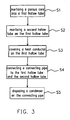
- FIG. 3 is a manufacturing process of the heat transfer device in accordance with a preferred embodiment of the present invention.
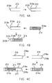
- FIGs 4A-4F show a detailed manufacturing process of the heat transfer device in accordance with a preferred embodiment of the present invention.
- FIG. 5 is the structure of the heat transfer device in accordance with a preferred embodiment of the present invention.
- FIG. 6 is a cross-sectional view of FIG. 5 along the A-A line.
- FIGs. 7A-7D show the structure of the heat conductor device in accordance with another preferred embodiment of the present invention.
- FIG. 3 is a manufacturing process of the heat transfer device in accordance with a preferred embodiment of the present invention.
- the manufacturing process includes: mortising a porous core into a first hollow tube (S1); mortising a second hollow tube on the first hollow tube (S2); covering a heat conductor on the first hollow tube (S3); connecting a connecting pipe to the first hollow tube and the second hollow tube (S4); and disposing a condenser on the connecting pipe (S5).
- the detailed manufacturing process will be illustrated as follows.
- FIGs 4A-4F show a detailed manufacturing process of the heat transfer device in accordance with a preferred embodiment of the present invention.
- a first hollow tube 212 is provided.
- the first hollow tube 212 in this embodiment is a hollow tube with a closed end.
- the closed end of the first hollow tube 212 has a first surface 212a.
- a hole-punching is performed to form a first hole 212b.
- the porous core 214 is mortised into the first hollow tube 212.
- the porous core 214 has a fluid channel 214a therein for injecting a working fluid therein.
- the outer surface of the porous core 214 for example has one or more trenches so that after the porous core 214 is mortised to the first hollow tube 212 the one or more trenches can form one or more vapor channels 214b with the inner surface of the first hollow tube 212.
- a second hollow tube 216 is provided.
- the second hollow tube 216 in this embodiment is a hollow tube with a closed end.
- the closed end of the second hollow tube 216 has a second surface 216a.
- a hole-punching is performed to form a second hole 216b.
- a hole-widening step can be performed at the opposite end of the second hollow tube 216 to facilitate mortising the second hollow tube 216 to the first hollow tube 212.
- a heat conductor 220 is covered on the first hollow tube 212 to form an evaporator 210.
- the heat conductor 220 includes a first heat conducting block 222 and a second heat conducting block 224.
- the evaporator 210 is covered by mortising the first heat conducting block 222 and the second heat conducting block 224.
- a press module 250 with a sealing function is used to press the mortised area where the second hollow tube 216 and the porous core 214 are mortised, so that the mortised area is deformed and the second hollow tube 216 can tightly contact the porous core 214 to prevent the working fluid from directly flowing into the vapor channel 214b. Hence, there is no concern of internal leakage inside the evaporator.
- a connecting pipe 230 is connected to the first hollow tube 212 and the second hollow tube 216.
- the connecting pipe 230 and the first hollow tube 212 are connected by mortising an end of the connecting pipe 230 to the first hole 212b and welding; the connecting pipe 230 and the second hollow tube 216 are connected by mortising an end of the connecting pipe 230 to the second hole 216b and welding.
- a condenser 240 is disposed on the connecting pipe 230 to form the heat transfer device 200 of the present invention.
- the present invention does not require the fusing or fusing and thermal connecting technology like the conventional manufacturing methods. Therefore, the present invention can simplify the manufacturing process and reduce the cost.
- the first and second hollow tubes of the present invention use a thinner metal shell. By pressing an area where the first hollow tube and the first hollow tube are mortised together, the mortised area will be deformed and the first hollow tube and the second hollow tube can contact tightly the porous core to prevent the working fluid from leakage into the vapor channel.
- first and second hollow tubes of the present invention are closed ended tube, a cap is not required to be welded to the closed end (the welding step is required only at the connection to the connecting pipe).
- the present invention can reduce the number of the welding steps to prevent the porous core from damaged due to the welding step.
- FIG. 5 is the structure of the heat transfer device manufactured in accordance with a preferred embodiment of the present invention.
- FIG. 6 is a cross-sectional view of FIG. 5 along the A-A line.
- the heat transfer device 200 for transferring a heating source from a heating device 20.
- the heat transfer device 200 at least comprises: an evaporator 210, a heat conductor 220 and a connecting pipe 230.
- the evaporator 210 comprises: a first hollow tube 212; a porous core 214 mortised inside the first hollow tube 212; a second hollow tube 216 mortised on the first hollow tube 212.
- the heat conductor 220 covers the evaporator 210.
- the heat conductor 220 is on the heating device 20.
- the connecting pipe 230 is connected to first and second hollow tubes 212 and 216.
- the connecting pipe 210 is used for containing a working fluid.
- the porous core 214 has a fluid channel 214a therein.
- the fluid channel 214a is connected to the fluid reservoir 217.
- the fluid reservoir 217 is a space inside the second hollow tube 216.
- the vapor channel 214b is connected to the connecting pipe 230.
- a condenser 240 is disposed on the connecting pipe 230.
- the heating device 20 When the heating device 20 generates high heat, the working fluid in the porous core 214 will be heated up and becomes vapor. The capillarity attraction of the porous core 214 will attract the working fluid in the connecting pipe 230 back to the fluid channel 214a of the porous core 214. The vapor will go to the connecting pipe 230 via the vapor channel 214b. Further, the vapor entering into the condenser 240 will be condensed to the liquid state and goes back to the evaporator 210.
- the working fluid can circularly flow through the connecting pipe 230 (along the direction of the arrow as shown in FIG.5 ) by converting the working fluid between the gaseous state and the liquid state, so that the heat generated by the heating device 20 can be transferred out of the heating device 20.
- the heat conductor 220 comprises a first heat conducting block 222 having a heat conducting tenon 222a; and a second heat conducting block 224 having a mortise 224a corresponding to the heat conducting tenon 222a.
- the heat conducting tenon 222a is inserted into the mortise 224a so that the first and second heat conducting blocks 222 and 224 can cover the evaporator 210.
- the high heat generated by the heating device 20 can be uniformly conducted to the evaporator 210 via the heat conductor 220.
- the height of the tenon 222a is smaller than the depth of the mortise 224a to enhance the tightness between the tenon222a and the mortise 224a so that the first and second heat conducting blocks 222 and 224 can contact closely the outer wall of the evaporator 210 to obtain good heat conductivity.
- the heat conductor 220 comprises a first heat conducting block 222 and a second heat conducting block 224 to cover the evaporator 210.
- the heat conductor present is not limited to two heat conducting blocks. It can be mortised by several heat conducting blocks. Further, it is not limited to one evaporator covered by the heat conducting blocks.
- the heat conducting blocks also can cover several evaporators.
- the shape of the heat conducting blocks can be any shape so long as the heat conducting blocks can cover the evaporator after assembly. An example of the heat conductor will be illustrated as follows.
- FIGs. 7A-7D show the structure of the heat conductor device manufactured in accordance with another preferred embodiment of the present invention.
- the heat conductor 220 includes two heat conducting blocks (first heat conducting block 222 and second heat conducting block 224) and covers two evaporators (not shown).
- the heat conductor 220 includes three heat conducting blocks (first heat conducting block 222, second heat conducting block 224, and third heat conducting block 226) and covers two evaporators (not shown). Further, each of the above evaporators can be connected to an independent connecting pipe, or all evaporators can be connected to a single connecting pipe.
- the elements of the heat transfer device (the porous core, the first and second hollow tube, and the heat conductor) are mortised together so as to simplify the manufacturing process, and reduce the cost. Further, the evaporator is tightly covered and fixed by the heat conductor so that the heat generated by the heating device can be uniformly conducted to the evaporator to enhance the heat conductivity.
Landscapes
- Engineering & Computer Science (AREA)
- General Engineering & Computer Science (AREA)
- Physics & Mathematics (AREA)
- Thermal Sciences (AREA)
- Sustainable Development (AREA)
- Mechanical Engineering (AREA)
- Life Sciences & Earth Sciences (AREA)
- Heat-Exchange Devices With Radiators And Conduit Assemblies (AREA)
- Cooling Or The Like Of Semiconductors Or Solid State Devices (AREA)
- Instantaneous Water Boilers, Portable Hot-Water Supply Apparatuses, And Control Of Portable Hot-Water Supply Apparatuses (AREA)
- Air-Conditioning For Vehicles (AREA)
- Separation By Low-Temperature Treatments (AREA)
- Details Of Heat-Exchange And Heat-Transfer (AREA)
Claims (9)
- Verfahren zur Herstellung einer Wärmetransfervorrichtung, umfassend:Einzapfen eines porösen Kerns in ein erstes hohles Rohr;Aufzapfen eines zweiten hohlen Rohres auf das erste hohle Rohr;Bilden eines Verdampfers (210), der einen porösen Kern (214), ein erstes hohles Rohr (212) und ein zweites hohles Rohr (216) beinhaltet, wobei der poröse Kern (214) sich in dem ersten hohlen Rohr (212) befindet, das erste hohle Rohr (212) ein offenes Ende hat, und das zweite hohle Rohr (216) ein offenes Ende hat, das mit dem einen offenen Ende des ersten hohlen Rohres (212) verbunden ist;Bedecken des ersten hohlen Rohres (212) mit einem Wärmeleiter (220); undVerbinden einer Verbindungsleitung (230) mit dem ersten hohlen Rohr (212) und dem zweiten hohlen Rohr (216), wobei ein erstes Ende der Verbindungsleitung (230) in Fluidverbindung mit dem anderen Ende des ersten hohlen Rohres (212) und ein zweite Ende der Verbindungsleitung (230) steht in Fluidverbindung mit dem anderen Ende des zweiten hohlen Rohres (216) ist, wobei der Schritt des Bildens des Verdampfers (210) umfasst:Einzapfen des porösen Kerns (214) in das erste hohle Rohr (212) durch das eine offene Ende des ersten hohlen Rohrs (212); undAufzapfen des einen offenen Endes des zweiten hohlen Rohres (216) auf das offene Ende des ersten hohlen Rohres (212).
- Verfahren gemäß Anspruch 1, wobei das erste hohle Rohr (212) ein geschlossenes Ende hat und das erste geschlossene Ende vor dem Schritt des Einzapfens des porösen Kerns (214) in das erste hohle Rohr (212) eine erste Fläche (212a) aufweist, des Weiteren umfassend Lochstanzen, um ein erstes Loch (212b) zu bilden.
- Verfahren gemäß Anspruch 2, wobei die Verbindungsleitung (230) und das erste hohle Rohr (212) durch Verzapfen und Schweißen eines Endes der ersten Verbindungsleitung (230) mit dem ersten Loch (212b) verbunden sind.
- Verfahren gemäß Anspruch 1, wobei das zweite hohle Rohr (216) ein geschlossenes Ende hat, wobei das geschlossene Ende vor dem Schritt des Einzapfens des porösen Kerns (214) in das zweite hohle Rohr (216) eine zweite Fläche (216a) aufweist, des Weiteren umfassend Lochstanzen, um ein zweites Loch (216b) zu bilden.
- Verfahren gemäß Anspruch 4, weiter umfassend Lochaufweiten an dem gegenüberliegenden Ende des zweiten hohlen Rohres (216) gleichzeitig mit der Durchführung des Schrittes des Lochstanzens, um das zweite Loch (216b) zu bilden.
- Verfahren gemäß Anspruch 4, wobei die Verbindungsleitung (230) und das zweite hohle Rohr (216) durch Verzapfen eines Endes der Verbindungsleitung (230) mit dem zweiten Loch (216b) und Schweißen verbunden sind.
- Verfahren gemäß Anspruch 1, das weiter ein Pressmodul (250) mit einer Dichtfunktion verwendet, um einen Bereich zu pressen, in dem das zweite hohle Rohr (216) und der poröse Kern (214) zusammenverzapft sind.
- Verfahren gemäß Anspruch 1, das weiter einen Dampfkondensator (240) auf die Verbindungsleitung (230) nach dem Schritt des Verbindens der Verbindungsleitung (230) mit dem ersten hohlen Rohr (212) und dem zweiten hohlen Rohr (216) platziert.
- Verfahren gemäß Anspruch 1, wobei der Wärmeleiter einen ersten Wärmeleitungsblock (222) und einen zweiten Wärmeleitungsblock (224) beinhaltet, wobei der erste Wärmeleitungsblock (222) und der zweite Wärmeleitungsblock (224) zusammenverzapft sind, um das erste hohle Rohr (212) zu überdecken.
Priority Applications (1)
| Application Number | Priority Date | Filing Date | Title |
|---|---|---|---|
| EP07024250A EP1906128A3 (de) | 2003-10-27 | 2004-10-22 | Vorrichtung zur Wärmeübertragung |
Applications Claiming Priority (2)
| Application Number | Priority Date | Filing Date | Title |
|---|---|---|---|
| CN200310102364 | 2003-10-27 | ||
| CNB2003101023642A CN1303494C (zh) | 2003-10-27 | 2003-10-27 | 热移除装置及其制造方法 |
Related Child Applications (1)
| Application Number | Title | Priority Date | Filing Date |
|---|---|---|---|
| EP07024250A Division EP1906128A3 (de) | 2003-10-27 | 2004-10-22 | Vorrichtung zur Wärmeübertragung |
Publications (2)
| Publication Number | Publication Date |
|---|---|
| EP1528349A1 EP1528349A1 (de) | 2005-05-04 |
| EP1528349B1 true EP1528349B1 (de) | 2008-05-14 |
Family
ID=34398368
Family Applications (2)
| Application Number | Title | Priority Date | Filing Date |
|---|---|---|---|
| EP07024250A Ceased EP1906128A3 (de) | 2003-10-27 | 2004-10-22 | Vorrichtung zur Wärmeübertragung |
| EP04025179A Expired - Lifetime EP1528349B1 (de) | 2003-10-27 | 2004-10-22 | Verfahren zur Herstellung einer Wärmetauschervorrichtung |
Family Applications Before (1)
| Application Number | Title | Priority Date | Filing Date |
|---|---|---|---|
| EP07024250A Ceased EP1906128A3 (de) | 2003-10-27 | 2004-10-22 | Vorrichtung zur Wärmeübertragung |
Country Status (5)
| Country | Link |
|---|---|
| EP (2) | EP1906128A3 (de) |
| CN (1) | CN1303494C (de) |
| AT (1) | ATE395567T1 (de) |
| DE (1) | DE602004013702D1 (de) |
| ES (1) | ES2305643T3 (de) |
Families Citing this family (23)
| Publication number | Priority date | Publication date | Assignee | Title |
|---|---|---|---|---|
| US7116840B2 (en) | 2002-10-31 | 2006-10-03 | Microsoft Corporation | Decoding and error correction in 2-D arrays |
| US7133563B2 (en) | 2002-10-31 | 2006-11-07 | Microsoft Corporation | Passive embedded interaction code |
| US7583842B2 (en) | 2004-01-06 | 2009-09-01 | Microsoft Corporation | Enhanced approach of m-array decoding and error correction |
| US7263224B2 (en) | 2004-01-16 | 2007-08-28 | Microsoft Corporation | Strokes localization by m-array decoding and fast image matching |
| US7607076B2 (en) | 2005-02-18 | 2009-10-20 | Microsoft Corporation | Embedded interaction code document |
| US7826074B1 (en) | 2005-02-25 | 2010-11-02 | Microsoft Corporation | Fast embedded interaction code printing with custom postscript commands |
| US7421439B2 (en) | 2005-04-22 | 2008-09-02 | Microsoft Corporation | Global metadata embedding and decoding |
| US7599560B2 (en) | 2005-04-22 | 2009-10-06 | Microsoft Corporation | Embedded interaction code recognition |
| US7400777B2 (en) | 2005-05-25 | 2008-07-15 | Microsoft Corporation | Preprocessing for information pattern analysis |
| US7729539B2 (en) | 2005-05-31 | 2010-06-01 | Microsoft Corporation | Fast error-correcting of embedded interaction codes |
| US7580576B2 (en) | 2005-06-02 | 2009-08-25 | Microsoft Corporation | Stroke localization and binding to electronic document |
| US7619607B2 (en) | 2005-06-30 | 2009-11-17 | Microsoft Corporation | Embedding a pattern design onto a liquid crystal display |
| US7817816B2 (en) | 2005-08-17 | 2010-10-19 | Microsoft Corporation | Embedded interaction code enabled surface type identification |
| US7622182B2 (en) | 2005-08-17 | 2009-11-24 | Microsoft Corporation | Embedded interaction code enabled display |
| EP1780804A1 (de) * | 2005-10-25 | 2007-05-02 | L&C Lighting Technology Corp. | Leuchtdiodenbauteil mit einer aktiven Kühlungseinrichtung |
| JP2012149819A (ja) * | 2011-01-19 | 2012-08-09 | Fujitsu Ltd | ループ型ヒートパイプ及び電子機器 |
| CN104519706A (zh) * | 2013-09-26 | 2015-04-15 | 君瞻科技股份有限公司 | 热管 |
| JP6230020B2 (ja) * | 2013-10-02 | 2017-11-15 | 国立大学法人名古屋大学 | ループ型ヒートパイプ及びループ型ヒートパイプの製造方法 |
| CN105423790A (zh) * | 2015-12-04 | 2016-03-23 | 王轶珂 | 一种吸热散热装置 |
| DE102016105592A1 (de) * | 2016-03-24 | 2017-09-28 | Benteler Automobiltechnik Gmbh | Heizvorrichtung sowie Verfahren zur Beheizung eines Kraftfahrzeuges |
| JP6805438B2 (ja) * | 2016-10-19 | 2020-12-23 | 国立大学法人東海国立大学機構 | 熱交換器、蒸発体、および装置 |
| CN107317574B (zh) * | 2017-06-09 | 2020-08-11 | 南京理工大学 | 自冷却高压脉冲开关器件 |
| EP4019252A1 (de) * | 2020-12-23 | 2022-06-29 | ABB Schweiz AG | Wärmeübertragungsvorrichtung und verfahren zur herstellung einer solchen vorrichtung |
Family Cites Families (10)
| Publication number | Priority date | Publication date | Assignee | Title |
|---|---|---|---|---|
| US3387653A (en) * | 1967-01-26 | 1968-06-11 | Wakefield Eng Inc | Heat transfer apparatus |
| US3750745A (en) * | 1970-07-06 | 1973-08-07 | R Moore | High heat flux heat pipe |
| JPS5347057A (en) * | 1976-10-13 | 1978-04-27 | Oki Densen Kk | Heat pipe and production thereof |
| DE3042985A1 (de) * | 1980-11-14 | 1982-06-24 | Kabel- und Metallwerke Gutehoffnungshütte AG, 3000 Hannover | Anordnung zur temperierung von gegenstaenden insbesondere von elektronischen bauteilen |
| JPS602892A (ja) * | 1983-06-20 | 1985-01-09 | Toshiba Corp | ヒ−トパイプ |
| DE3679978D1 (de) * | 1985-12-13 | 1991-08-01 | Hasler Ag Ascom | Verfahren und vorrichtung zum abfuehren der verlustwaerme wenigstens einer baugruppe elektrischer elemente. |
| JP3450148B2 (ja) * | 1997-03-07 | 2003-09-22 | 三菱電機株式会社 | ループ型ヒートパイプ |
| JP3857774B2 (ja) * | 1997-03-19 | 2006-12-13 | 株式会社フジクラ | ヒートパイプの保持構造 |
| US6382309B1 (en) * | 2000-05-16 | 2002-05-07 | Swales Aerospace | Loop heat pipe incorporating an evaporator having a wick that is liquid superheat tolerant and is resistant to back-conduction |
| CN2543122Y (zh) * | 2002-03-20 | 2003-04-02 | 鸿富锦精密工业(深圳)有限公司 | 热管式散热器 |
-
2003
- 2003-10-27 CN CNB2003101023642A patent/CN1303494C/zh not_active Expired - Fee Related
-
2004
- 2004-10-22 EP EP07024250A patent/EP1906128A3/de not_active Ceased
- 2004-10-22 ES ES04025179T patent/ES2305643T3/es not_active Expired - Lifetime
- 2004-10-22 AT AT04025179T patent/ATE395567T1/de not_active IP Right Cessation
- 2004-10-22 EP EP04025179A patent/EP1528349B1/de not_active Expired - Lifetime
- 2004-10-22 DE DE602004013702T patent/DE602004013702D1/de not_active Expired - Lifetime
Also Published As
| Publication number | Publication date |
|---|---|
| CN1303494C (zh) | 2007-03-07 |
| ES2305643T3 (es) | 2008-11-01 |
| EP1906128A3 (de) | 2008-04-09 |
| ATE395567T1 (de) | 2008-05-15 |
| CN1612083A (zh) | 2005-05-04 |
| DE602004013702D1 (de) | 2008-06-26 |
| EP1906128A2 (de) | 2008-04-02 |
| EP1528349A1 (de) | 2005-05-04 |
Similar Documents
| Publication | Publication Date | Title |
|---|---|---|
| US7454835B2 (en) | Method of manufacturing heat transfer device | |
| EP1528349A1 (de) | Wärmetauschervorrichtung und Verfahren zu dessen Herstellung | |
| US5029389A (en) | Method of making a heat pipe with improved end cap | |
| US20020021556A1 (en) | Vapor chamber with integrated pin array | |
| US6439298B1 (en) | Cylindrical heat radiator | |
| US10240873B2 (en) | Joint assembly of vapor chambers | |
| TW201425855A (zh) | 熱導管及其製造方法 | |
| CN107087374B (zh) | 一种平板式微型环路热管及其注液排气方法 | |
| CN109819635B (zh) | 散热装置 | |
| US7111394B2 (en) | Hybrid loop heat pipe | |
| JP2007317825A (ja) | ヒートシンクおよびそれを用いた電子装置 | |
| CN100582637C (zh) | 具有楔形毛细管的微型热管 | |
| CN107087375B (zh) | 一种蒸发室和蒸汽管道不直接连通的平板式环路热管 | |
| CN107094360B (zh) | 一种平板式微型环路热管系统 | |
| JP3511604B2 (ja) | 熱サイフォン型熱移動体 | |
| CN109470069B (zh) | 一种热管换热套件及其制造方法 | |
| CN118785652A (zh) | 热插销装置、多级热管及服务器机柜 | |
| CN115507686A (zh) | 热管 | |
| CN117202598A (zh) | 回路型二相流散热器 | |
| CN110958814B (zh) | 一种服务器用柔性相变传热降温器 | |
| CN116156846A (zh) | 一种散热装置 | |
| CN107091582A (zh) | 一种毛细芯毛细力变化的平板式微型环路热管 | |
| KR100510613B1 (ko) | 히트 파이프 | |
| CN221962190U (zh) | 浸没式散热装置 | |
| WO2002011506A2 (en) | Vapor chamber with integrated pin array |
Legal Events
| Date | Code | Title | Description |
|---|---|---|---|
| PUAI | Public reference made under article 153(3) epc to a published international application that has entered the european phase |
Free format text: ORIGINAL CODE: 0009012 |
|
| AK | Designated contracting states |
Kind code of ref document: A1 Designated state(s): AT BE BG CH CY CZ DE DK EE ES FI FR GB GR HU IE IT LI LU MC NL PL PT RO SE SI SK TR |
|
| AX | Request for extension of the european patent |
Extension state: AL HR LT LV MK |
|
| RIN1 | Information on inventor provided before grant (corrected) |
Inventor name: HUANG, BIN-JUINE Inventor name: LAM, CHERN-SHI Inventor name: WANG, CHIH-HUNG Inventor name: YEN, YU-YUAN Inventor name: HUANG, HUAN-HSIANG |
|
| 17P | Request for examination filed |
Effective date: 20051103 |
|
| AKX | Designation fees paid |
Designated state(s): AT BE BG CH CY CZ DE DK EE ES FI FR GB GR HU IE IT LI LU MC NL PL PT RO SE SI SK TR |
|
| 17Q | First examination report despatched |
Effective date: 20060113 |
|
| RAP1 | Party data changed (applicant data changed or rights of an application transferred) |
Owner name: ADVANCED THERMAL DEVICE INC. |
|
| GRAP | Despatch of communication of intention to grant a patent |
Free format text: ORIGINAL CODE: EPIDOSNIGR1 |
|
| RTI1 | Title (correction) |
Free format text: METHOD FOR MANUFACTURING A HEAT TRANSFER DEVICE |
|
| GRAS | Grant fee paid |
Free format text: ORIGINAL CODE: EPIDOSNIGR3 |
|
| GRAA | (expected) grant |
Free format text: ORIGINAL CODE: 0009210 |
|
| AK | Designated contracting states |
Kind code of ref document: B1 Designated state(s): AT BE BG CH CY CZ DE DK EE ES FI FR GB GR HU IE IT LI LU MC NL PL PT RO SE SI SK TR |
|
| REG | Reference to a national code |
Ref country code: GB Ref legal event code: FG4D |
|
| REG | Reference to a national code |
Ref country code: CH Ref legal event code: EP |
|
| REG | Reference to a national code |
Ref country code: IE Ref legal event code: FG4D Free format text: LANGUAGE OF EP DOCUMENT: FRENCH |
|
| REF | Corresponds to: |
Ref document number: 602004013702 Country of ref document: DE Date of ref document: 20080626 Kind code of ref document: P |
|
| REG | Reference to a national code |
Ref country code: GR Ref legal event code: EP Ref document number: 20080401926 Country of ref document: GR |
|
| PG25 | Lapsed in a contracting state [announced via postgrant information from national office to epo] |
Ref country code: SI Free format text: LAPSE BECAUSE OF FAILURE TO SUBMIT A TRANSLATION OF THE DESCRIPTION OR TO PAY THE FEE WITHIN THE PRESCRIBED TIME-LIMIT Effective date: 20080514 |
|
| PG25 | Lapsed in a contracting state [announced via postgrant information from national office to epo] |
Ref country code: FI Free format text: LAPSE BECAUSE OF FAILURE TO SUBMIT A TRANSLATION OF THE DESCRIPTION OR TO PAY THE FEE WITHIN THE PRESCRIBED TIME-LIMIT Effective date: 20080514 |
|
| REG | Reference to a national code |
Ref country code: ES Ref legal event code: FG2A Ref document number: 2305643 Country of ref document: ES Kind code of ref document: T3 |
|
| PG25 | Lapsed in a contracting state [announced via postgrant information from national office to epo] |
Ref country code: AT Free format text: LAPSE BECAUSE OF FAILURE TO SUBMIT A TRANSLATION OF THE DESCRIPTION OR TO PAY THE FEE WITHIN THE PRESCRIBED TIME-LIMIT Effective date: 20080514 Ref country code: PL Free format text: LAPSE BECAUSE OF FAILURE TO SUBMIT A TRANSLATION OF THE DESCRIPTION OR TO PAY THE FEE WITHIN THE PRESCRIBED TIME-LIMIT Effective date: 20080514 |
|
| PG25 | Lapsed in a contracting state [announced via postgrant information from national office to epo] |
Ref country code: CZ Free format text: LAPSE BECAUSE OF FAILURE TO SUBMIT A TRANSLATION OF THE DESCRIPTION OR TO PAY THE FEE WITHIN THE PRESCRIBED TIME-LIMIT Effective date: 20080514 Ref country code: SE Free format text: LAPSE BECAUSE OF FAILURE TO SUBMIT A TRANSLATION OF THE DESCRIPTION OR TO PAY THE FEE WITHIN THE PRESCRIBED TIME-LIMIT Effective date: 20080814 Ref country code: DK Free format text: LAPSE BECAUSE OF FAILURE TO SUBMIT A TRANSLATION OF THE DESCRIPTION OR TO PAY THE FEE WITHIN THE PRESCRIBED TIME-LIMIT Effective date: 20080514 Ref country code: PT Free format text: LAPSE BECAUSE OF FAILURE TO SUBMIT A TRANSLATION OF THE DESCRIPTION OR TO PAY THE FEE WITHIN THE PRESCRIBED TIME-LIMIT Effective date: 20081014 |
|
| PG25 | Lapsed in a contracting state [announced via postgrant information from national office to epo] |
Ref country code: RO Free format text: LAPSE BECAUSE OF FAILURE TO SUBMIT A TRANSLATION OF THE DESCRIPTION OR TO PAY THE FEE WITHIN THE PRESCRIBED TIME-LIMIT Effective date: 20080514 Ref country code: SK Free format text: LAPSE BECAUSE OF FAILURE TO SUBMIT A TRANSLATION OF THE DESCRIPTION OR TO PAY THE FEE WITHIN THE PRESCRIBED TIME-LIMIT Effective date: 20080514 |
|
| PLBE | No opposition filed within time limit |
Free format text: ORIGINAL CODE: 0009261 |
|
| STAA | Information on the status of an ep patent application or granted ep patent |
Free format text: STATUS: NO OPPOSITION FILED WITHIN TIME LIMIT |
|
| 26N | No opposition filed |
Effective date: 20090217 |
|
| PG25 | Lapsed in a contracting state [announced via postgrant information from national office to epo] |
Ref country code: EE Free format text: LAPSE BECAUSE OF FAILURE TO SUBMIT A TRANSLATION OF THE DESCRIPTION OR TO PAY THE FEE WITHIN THE PRESCRIBED TIME-LIMIT Effective date: 20080514 Ref country code: BG Free format text: LAPSE BECAUSE OF FAILURE TO SUBMIT A TRANSLATION OF THE DESCRIPTION OR TO PAY THE FEE WITHIN THE PRESCRIBED TIME-LIMIT Effective date: 20080814 |
|
| PG25 | Lapsed in a contracting state [announced via postgrant information from national office to epo] |
Ref country code: MC Free format text: LAPSE BECAUSE OF NON-PAYMENT OF DUE FEES Effective date: 20081031 |
|
| REG | Reference to a national code |
Ref country code: CH Ref legal event code: PL |
|
| PG25 | Lapsed in a contracting state [announced via postgrant information from national office to epo] |
Ref country code: CH Free format text: LAPSE BECAUSE OF NON-PAYMENT OF DUE FEES Effective date: 20081031 Ref country code: IE Free format text: LAPSE BECAUSE OF NON-PAYMENT OF DUE FEES Effective date: 20081022 Ref country code: LI Free format text: LAPSE BECAUSE OF NON-PAYMENT OF DUE FEES Effective date: 20081031 |
|
| PG25 | Lapsed in a contracting state [announced via postgrant information from national office to epo] |
Ref country code: HU Free format text: LAPSE BECAUSE OF FAILURE TO SUBMIT A TRANSLATION OF THE DESCRIPTION OR TO PAY THE FEE WITHIN THE PRESCRIBED TIME-LIMIT Effective date: 20081115 Ref country code: CY Free format text: LAPSE BECAUSE OF FAILURE TO SUBMIT A TRANSLATION OF THE DESCRIPTION OR TO PAY THE FEE WITHIN THE PRESCRIBED TIME-LIMIT Effective date: 20080514 Ref country code: LU Free format text: LAPSE BECAUSE OF NON-PAYMENT OF DUE FEES Effective date: 20081022 |
|
| PG25 | Lapsed in a contracting state [announced via postgrant information from national office to epo] |
Ref country code: TR Free format text: LAPSE BECAUSE OF FAILURE TO SUBMIT A TRANSLATION OF THE DESCRIPTION OR TO PAY THE FEE WITHIN THE PRESCRIBED TIME-LIMIT Effective date: 20080514 |
|
| PGFP | Annual fee paid to national office [announced via postgrant information from national office to epo] |
Ref country code: BE Payment date: 20131016 Year of fee payment: 10 |
|
| PGFP | Annual fee paid to national office [announced via postgrant information from national office to epo] |
Ref country code: IT Payment date: 20131028 Year of fee payment: 10 Ref country code: NL Payment date: 20131010 Year of fee payment: 10 Ref country code: ES Payment date: 20131016 Year of fee payment: 10 Ref country code: GR Payment date: 20131009 Year of fee payment: 10 |
|
| REG | Reference to a national code |
Ref country code: NL Ref legal event code: V1 Effective date: 20150501 |
|
| REG | Reference to a national code |
Ref country code: GR Ref legal event code: ML Ref document number: 20080401926 Country of ref document: GR Effective date: 20150505 |
|
| PG25 | Lapsed in a contracting state [announced via postgrant information from national office to epo] |
Ref country code: BE Free format text: LAPSE BECAUSE OF NON-PAYMENT OF DUE FEES Effective date: 20141031 |
|
| PG25 | Lapsed in a contracting state [announced via postgrant information from national office to epo] |
Ref country code: NL Free format text: LAPSE BECAUSE OF NON-PAYMENT OF DUE FEES Effective date: 20150501 Ref country code: IT Free format text: LAPSE BECAUSE OF NON-PAYMENT OF DUE FEES Effective date: 20141022 Ref country code: GR Free format text: LAPSE BECAUSE OF NON-PAYMENT OF DUE FEES Effective date: 20150505 |
|
| REG | Reference to a national code |
Ref country code: FR Ref legal event code: PLFP Year of fee payment: 12 |
|
| REG | Reference to a national code |
Ref country code: ES Ref legal event code: FD2A Effective date: 20151126 |
|
| PGFP | Annual fee paid to national office [announced via postgrant information from national office to epo] |
Ref country code: DE Payment date: 20151027 Year of fee payment: 12 Ref country code: GB Payment date: 20151026 Year of fee payment: 12 |
|
| PG25 | Lapsed in a contracting state [announced via postgrant information from national office to epo] |
Ref country code: ES Free format text: LAPSE BECAUSE OF NON-PAYMENT OF DUE FEES Effective date: 20141023 |
|
| PGFP | Annual fee paid to national office [announced via postgrant information from national office to epo] |
Ref country code: FR Payment date: 20151029 Year of fee payment: 12 |
|
| REG | Reference to a national code |
Ref country code: DE Ref legal event code: R119 Ref document number: 602004013702 Country of ref document: DE |
|
| GBPC | Gb: european patent ceased through non-payment of renewal fee |
Effective date: 20161022 |
|
| REG | Reference to a national code |
Ref country code: FR Ref legal event code: ST Effective date: 20170630 |
|
| PG25 | Lapsed in a contracting state [announced via postgrant information from national office to epo] |
Ref country code: FR Free format text: LAPSE BECAUSE OF NON-PAYMENT OF DUE FEES Effective date: 20161102 Ref country code: DE Free format text: LAPSE BECAUSE OF NON-PAYMENT OF DUE FEES Effective date: 20170503 Ref country code: GB Free format text: LAPSE BECAUSE OF NON-PAYMENT OF DUE FEES Effective date: 20161022 |