EP1528310B1 - Weldable clamp with transport fixing device for fixing means - Google Patents
Weldable clamp with transport fixing device for fixing means Download PDFInfo
- Publication number
- EP1528310B1 EP1528310B1 EP04016657A EP04016657A EP1528310B1 EP 1528310 B1 EP1528310 B1 EP 1528310B1 EP 04016657 A EP04016657 A EP 04016657A EP 04016657 A EP04016657 A EP 04016657A EP 1528310 B1 EP1528310 B1 EP 1528310B1
- Authority
- EP
- European Patent Office
- Prior art keywords
- clamp
- fastening
- bracket
- transport
- shells
- Prior art date
- Legal status (The legal status is an assumption and is not a legal conclusion. Google has not performed a legal analysis and makes no representation as to the accuracy of the status listed.)
- Active
Links
Images
Classifications
-
- F—MECHANICAL ENGINEERING; LIGHTING; HEATING; WEAPONS; BLASTING
- F16—ENGINEERING ELEMENTS AND UNITS; GENERAL MEASURES FOR PRODUCING AND MAINTAINING EFFECTIVE FUNCTIONING OF MACHINES OR INSTALLATIONS; THERMAL INSULATION IN GENERAL
- F16L—PIPES; JOINTS OR FITTINGS FOR PIPES; SUPPORTS FOR PIPES, CABLES OR PROTECTIVE TUBING; MEANS FOR THERMAL INSULATION IN GENERAL
- F16L47/00—Connecting arrangements or other fittings specially adapted to be made of plastics or to be used with pipes made of plastics
- F16L47/02—Welded joints; Adhesive joints
- F16L47/03—Welded joints with an electrical resistance incorporated in the joint
Definitions
- the invention relates to a welding clamp and in particular the provision of fasteners for the welding clamp.
- Such welding clamps are placed over plastic pipes or plastic pipe connections. They have on their inside welding devices, such as welding wires, which provides in the supply of electric current for a tight weld the clamp with the pipe section on which the clamp sits.
- Such welding can simply serve to connect two pipes, but it is also possible to supply a continuous plastic pipe in a simple manner with a tightly inserted branch by placing a weld, which has an additional pipe outlet.
- the EP 0 733 846 A2 relates to a device for drilling plastic pipes of supply lines.
- the invention relates to a device for drilling plastic pipes of supply lines, consisting of a provided with a radially arranged neck saddle in the form of a Rohschschale, which is provided with a mat-shaped Bankdrahtan für apschale, which is provided with a mat-shaped Bankdrahtan für apschale, which is provided with a mat-shaped Banktan extract on its inner surface, and an abutment in the form of a second half-shell, the to mechanically clamp together with the saddle. It is the object of the invention, with simple means and in a simple manner to achieve a secure fit of the saddle on the supply line and thus an absolute tightness at the location of the saddle.
- the invention consists in integrally joining parallel legs in tangential planes on both sides of the semicircular part of the saddle in such a way that the inner wall of the saddle extends beyond the median plane of the plastic tube and tangentially continues in this region (approached), that the side walls of the Abutment run parallel to this area or at an acute angle low degree that the inner wall of the saddle is also provided in its extending beyond the median plane of the plastic pipe and extending parallel to the side walls of the abutment part with mat-shaped Bankdrahtan eleven.
- a welding clamp according to the invention for fluid line pipes which has a plurality of clamp shells which are fastened to each other or are provided for attachment to one another, is characterized in that the welding clamp has a transport holder for the fastening means.
- the fasteners are provided by means of the transport bracket to the welding clamp, on the one hand ensures that they are always available in the assembly process where they are needed, on the other hand, this allows the worker the free use of his hands when attaching the clamp or the clamp shells.
- a loss of fasteners is no longer possible, and easy access to the fasteners in the transport bracket on the welding clamp allows faster and easier work.
- the transport bracket is designed so that the fasteners can be easily removed.
- an advantageous embodiment of the invention is, in the case where the fastening means are screws, to provide a transport holder having recesses for inserting or screwing a screw end, in particular the threaded end of the screws. The screws are then ready for access in the transport holder and can be easily removed.
- fixing means for the end or the threaded end, in particular with inwardly projecting webs or female thread sections.
- Such fixing means serve to ensure adequate protection against loss of the fasteners or screws, and on the other hand they are designed so that the worker can easily remove the fasteners by hand in order to then use them for assembly.
- the clamp shells on flange webs in which mounting holes are provided for the fastening means, wherein the transport bracket, in particular the male or Einschraubagen is arranged next to the mounting holes in the flange webs or are. Due to the spatial proximity thus brought about between the transport holder and the fastening bores, a quick and reliable transfer of the fastening means is made possible.
- a welding clamp according to the invention may have all the features described herein individually or in combination.
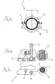
- FIG. 1 shows a welding clamp 1, which comprises an upper clamp shell 7 and a lower clamp shell 8.
- the two clamp shells 7, 8 surround the tube 9, on which the welding is to take place.
- FIG. 1 the flange web 2 of the upper clamp shell 7 can be seen, which is discussed in more detail in the explanation of the two other figures.
- the flange web is a through hole 5 through which a fastening screw 3 is inserted through the end of the welding clamp 1 at the pipe.
- the through hole 5 is a part of the entire attachment.
- an internal thread hole (not shown here) via which then the attachment of the clamp shells on the pipe.
- the flange web 2 has a blind hole 4 introduced from above, which serves as a transport holder for a fastening screw 3.
- the blind hole 4 are, as in the enlargements of FIGS. 2 and 3 can be seen, arranged three retaining webs 6, which help to fix the lower end of the screw 3 after insertion into the blind hole 4 so far that accidental falling out is prevented.
Landscapes
- Engineering & Computer Science (AREA)
- General Engineering & Computer Science (AREA)
- Mechanical Engineering (AREA)
- Clamps And Clips (AREA)
- Flanged Joints, Insulating Joints, And Other Joints (AREA)
Abstract
Description
Die Erfindung betrifft eine Schweißschelle und speziell die Bereitstellung von Befestigungsmitteln für die Schweißschelle. Solche Schweißschellen werden über Kunststoffrohre oder Kunststoffrohr-Verbindungen gesetzt. Sie weisen an ihrer Innenseite Schweißvorrichtungen, beispielsweise Schweißdrähte auf, welche bei der Versorgung mit elektrischem Strom für eine dichte Schweißverbindung der Schelle mit dem Rohrstück, auf dem die Schelle sitzt, sorgt. Eine solche Verschweißung kann einfach der Verbindung zweier Rohre dienen, es ist aber auch möglich, durch das Aufsetzen einer Schweißstelle, die einen zusätzlichen Rohrabgang aufweist, ein durchgehendes Kunststoffrohr in einfacher Weise mit einer dicht eingebrachten Verzweigung zu versorgen.The invention relates to a welding clamp and in particular the provision of fasteners for the welding clamp. Such welding clamps are placed over plastic pipes or plastic pipe connections. They have on their inside welding devices, such as welding wires, which provides in the supply of electric current for a tight weld the clamp with the pipe section on which the clamp sits. Such welding can simply serve to connect two pipes, but it is also possible to supply a continuous plastic pipe in a simple manner with a tightly inserted branch by placing a weld, which has an additional pipe outlet.
Bisher wurden Befestigungsmittel, beispielsweise Befestigungsschrauben zu der Verpackung der Schweißschelle lose beigelegt, sie mussten vor der Montage in der Hand gehalten oder in sonstiger Weise bereitgehalten werden. Die Befestigung solcher Schweißschelle an Rohren ist oftmals mit einigem handwerklichen Aufwand verbunden, insbesondere müssen die aus einzelnen Schalen bestehenden Schweißschellen in ihrer Position am Rohr gehalten werden. Dazu muss ein Arbeiter oft schon beide Hände benützen, und wenn er gleichzeitig noch die Befestigungsmittel in der Hand halten oder aus einer Tasche hervorholen muss, kompliziert das den Anbringungsvorgang sehr.So far, fasteners, such as fastening screws were added loose to the packaging of the welding clamp, they had to be held in front of the assembly in the hand or kept in any other way. The attachment of such welding clamp to pipes is often associated with some manual effort, in particular, the existing of individual shells welding clamps must be kept in position on the pipe. To do this, a worker often has to use both hands, and if at the same time he has to hold the fasteners in his hand or pull them out of a pocket, this complicates the attachment process very much.
Die
Es ist deshalb ganz allgemein eine Aufgabe der vorliegenden Erfindung, den Montagevorgang für eine Schweißschelle zu vereinfachen, insbesondere die einfache Verfügbarkeit der Befestigungsmittel herzustellen.It is therefore quite a general object of the present invention to simplify the assembly process for a welding clamp, in particular to produce the simple availability of the fastening means.
Diese Aufgabe wird erfindungsgemäß durch eine Schweißschelle gemäß dem Anspruch 1 gelöst. Die Unteransprüche beschreiben bevorzugte Ausführungsformen der vorliegenden Erfindung.This object is achieved by a welding clamp according to claim 1. The subclaims describe preferred embodiments of the present invention.
Eine erfindungsgemäße Schweißschelle für Fluidleitungsrohre (also Rohre für gasförmige oder flüssige Medien), die mehrere Schellenschalen aufweist, die aneinander befestigt werden bzw. zur Befestigung aneinander vorgesehen sind, zeichnet sich dadurch aus, dass die Schweißschelle eine Transporthalterung für die Befestigungsmittel aufweist. Wenn die Befestigungsmittel mit Hilfe der Transporthalterung an der Schweißschelle vorgesehen sind, ist einerseits gewährleistet, dass sie beim Montagevorgang immer an dem Ort zur Verfügung stehen, wo sie gebraucht werden, andererseits gewährt dies dem Arbeiter die freie Verwendung seiner Hände beim Ansetzen der Schelle bzw. der Schellenschalen. Ein Verlust der Befestigungsmittel ist nicht mehr möglich, und der einfache Zugriff auf die Befestigungsmittel in der Transporthalterung an der Schweißschelle ermöglicht ein schnelleres und unkomplizierteres Arbeiten. Natürlich ist es dabei von Vorteil, wenn die Transporthalterung so ausgestaltet ist, dass die Befestigungsmittel leicht entnommen werden können.A welding clamp according to the invention for fluid line pipes (ie pipes for gaseous or liquid media), which has a plurality of clamp shells which are fastened to each other or are provided for attachment to one another, is characterized in that the welding clamp has a transport holder for the fastening means. If the fasteners are provided by means of the transport bracket to the welding clamp, on the one hand ensures that they are always available in the assembly process where they are needed, on the other hand, this allows the worker the free use of his hands when attaching the clamp or the clamp shells. A loss of fasteners is no longer possible, and easy access to the fasteners in the transport bracket on the welding clamp allows faster and easier work. Of course, it is advantageous if the transport bracket is designed so that the fasteners can be easily removed.
In obigem Sinne besteht eine vorteilhafte Ausführungsform der Erfindung darin, für den Fall, wo die Befestigungsmittel Schrauben sind, eine Transporthalterung vorzusehen, die Ausnehmungen zum Einstecken bzw. Einschrauben eines Schraubenendes, insbesondere des Gewindeendes der Schrauben aufweist. Die Schrauben stecken dann zugriffsbereit in der Transporthalterung und können problemlos entnommen werden.In the above sense, an advantageous embodiment of the invention is, in the case where the fastening means are screws, to provide a transport holder having recesses for inserting or screwing a screw end, in particular the threaded end of the screws. The screws are then ready for access in the transport holder and can be easily removed.
Dabei besteht die Möglichkeit, die Ausnehmungen mit Fixierungsmitteln für das Ende bzw. das Gewindeende zu versehen, insbesondere mit nach innen vorstehenden Stegen oder Innengewindeabschnitten. Solche Fixierungsmittel dienen dazu, eine ausreichende Sicherung gegen ein Verlieren der Befestigungsmittel bzw. Schrauben zu gewährleisten, und sie sind andererseits so ausgelegt, dass der Arbeiter die Befestigungsmittel leicht von Hand entnehmen kann, um sie dann zur Montage zu verwenden.It is possible to provide the recesses with fixing means for the end or the threaded end, in particular with inwardly projecting webs or female thread sections. Such fixing means serve to ensure adequate protection against loss of the fasteners or screws, and on the other hand they are designed so that the worker can easily remove the fasteners by hand in order to then use them for assembly.
Bei einer weiteren Ausführungsform der vorliegenden Erfindung weisen die Schellenschalen Flanschstege auf, in denen Befestigungsbohrungen für die Befestigungsmittel vorgesehen sind, wobei die Transporthalterung, insbesondere die Einsteck- oder Einschraubaufnahmen neben den Befestigungsbohrungen in den Flanschstegen angeordnet ist bzw. sind. Durch die so herbeigeführte räumliche Nähe zwischen der Transporthalterung und dem Befestigungsbohrungen ist ein schnelles und sicheres Überführen der Befestigungsmittel ermöglicht.In a further embodiment of the present invention, the clamp shells on flange webs, in which mounting holes are provided for the fastening means, wherein the transport bracket, in particular the male or Einschraubaufnahmen is arranged next to the mounting holes in the flange webs or are. Due to the spatial proximity thus brought about between the transport holder and the fastening bores, a quick and reliable transfer of the fastening means is made possible.
Eine erfindungsgemäße Schweißschelle kann alle hierin beschriebenen Merkmale einzeln oder in Kombination aufweisen.A welding clamp according to the invention may have all the features described herein individually or in combination.
Die Erfindung wird im Weiteren anhand der beiliegenden Zeichnungen näher erläutert. Es zeigen:
- Figur 1
- eine Stirnansicht einer Schweißschelle;
Figur 2- eine seitliche Ansicht mit einem Schnitt durch den Flanschsteg einer oberen Schellenschale der Schweißschelle mit einer Teilvergrößerung; und
Figur 3- eine Teilansicht von oben auf den Flanschsteg mit einer Ausschnittsvergrößerung.
- FIG. 1
- an end view of a welding clamp;
- FIG. 2
- a side view with a section through the flange web of an upper clamp shell of the welding clamp with a partial enlargement; and
- FIG. 3
- a partial view from above of the Flanschsteg with an enlarged detail.
Die
In
Die
Rechts neben der Durchgangsbohrung 5 weist der Flanschsteg 2 eine von oben eingeführte Sacklochbohrung 4 auf, die als Transporthalterung für eine Befestigungsschraube 3 dient. In der Sacklochbohrung 4 sind, wie in den Vergrößerungen der
Durch diese Konstruktion hat ein Arbeiter, nachdem er die Schellenschalen 7, 8 am Rohr angesetzt hat, unmittelbar Zugriff auf die Schraube 3, die er leicht von Hand aus dem Sackloch 4 herausdrehen kann. Er kann damit die Befestigung der Schellenschalen 7, 8 über die Durchgangsbohrung 5 und das (nicht dargestellte) Innengewinde in der unteren Schellenschale leicht durchführen. Die Befestigungsschrauben stehen immer unmittelbar am Verwendungsort zur Verfügung, sie müssen nicht in der Hand oder in sonstiger Weise bereit gehalten werden.By this construction, a worker, after he has the
Claims (4)
- A welded bracket for fluid conduit pipes for gaseous or liquid media, wherein the welded bracket (1) comprises a plurality of bracket shells (7, 8) which are fastened to each other by fastening screws (3) and fastening bores (5), characterised in that the welded bracket (1) comprises a transport mount (4) for the fastening screws (3) which is provided in addition to the fastening bores (5) for fastening the bracket shells (7, 8) to the pipe.
- The welded bracket according to claim 1, characterised in that the transport mount comprises cavities (4) for inserting and/or screwing in the threaded end of the fastening screws (3).
- The welded bracket according to claim 2, characterised in that the cavities comprise fixing means (6) for the threaded end, in particular inwardly protruding stays (6) or interior thread portions.
- The welded bracket according to any one of claims 1 to 3, characterised in that the bracket shells (7, 8) comprise flange stays (2) in which fastening bores (5) for the fastening screws (3) are provided, wherein the transport mount, in particular the insertion or screwing-in receptacles (4), is/are arranged next to the fastening bores (5) in the flange stays (2).
Applications Claiming Priority (2)
| Application Number | Priority Date | Filing Date | Title |
|---|---|---|---|
| DE20316743U | 2003-10-30 | ||
| DE20316743U DE20316743U1 (en) | 2003-10-30 | 2003-10-30 | Welding clamp with fastener transport bracket |
Publications (2)
| Publication Number | Publication Date |
|---|---|
| EP1528310A1 EP1528310A1 (en) | 2005-05-04 |
| EP1528310B1 true EP1528310B1 (en) | 2012-05-09 |
Family
ID=30129082
Family Applications (1)
| Application Number | Title | Priority Date | Filing Date |
|---|---|---|---|
| EP04016657A Active EP1528310B1 (en) | 2003-10-30 | 2004-07-15 | Weldable clamp with transport fixing device for fixing means |
Country Status (3)
| Country | Link |
|---|---|
| EP (1) | EP1528310B1 (en) |
| AT (1) | ATE557231T1 (en) |
| DE (1) | DE20316743U1 (en) |
Family Cites Families (4)
| Publication number | Priority date | Publication date | Assignee | Title |
|---|---|---|---|---|
| MC1468A1 (en) * | 1982-03-10 | 1983-06-17 | Innotec | ELECTROSOLDABLE BYPASS SOCKET FOR PLASTIC PIPES |
| FR2571121B1 (en) * | 1984-09-28 | 1987-04-03 | Gautier Emile | PIPE SLEEVE FOR INTERVENTION ON A LOADED SYNTHETIC MATERIAL PIPING |
| CH685403A5 (en) * | 1991-07-22 | 1995-06-30 | Fischer Georg Rohrleitung | Molding of thermoplastic material. |
| ATE195170T1 (en) | 1995-03-19 | 2000-08-15 | Immanuel Jeschke | DEVICE FOR DRILLING PLASTIC PIPES IN SUPPLY LINES |
-
2003
- 2003-10-30 DE DE20316743U patent/DE20316743U1/en not_active Expired - Lifetime
-
2004
- 2004-07-15 AT AT04016657T patent/ATE557231T1/en active
- 2004-07-15 EP EP04016657A patent/EP1528310B1/en active Active
Also Published As
| Publication number | Publication date |
|---|---|
| DE20316743U1 (en) | 2004-01-08 |
| EP1528310A1 (en) | 2005-05-04 |
| ATE557231T1 (en) | 2012-05-15 |
Similar Documents
| Publication | Publication Date | Title |
|---|---|---|
| AT408139B (en) | INSTALLATION DEVICE FOR PIPELINES | |
| DE2003517C3 (en) | Pipe clamp for pipe suspensions | |
| EP1388619B1 (en) | Device for fixing a pipe | |
| DE102015119506A1 (en) | Connection assembly for mounting rails | |
| DE4337467A1 (en) | Connection for dashboard module and vehicle body - uses wedge, which drops automatically into spaces between module and body | |
| DE102012024122A1 (en) | Holding system for holding and positioning long objects, such as hoses and cables, has connecting section with groove and spring as connecting elements, which are arranged behind one another in longitudinal direction of connecting section | |
| DE4125072C2 (en) | Fastening clamp for pipes, hoses, cables and pipelines | |
| EP1528310B1 (en) | Weldable clamp with transport fixing device for fixing means | |
| DE2441297A1 (en) | Universal pipe hanger - two semi circular clamp pieces and screw connection fitting to U shaped hanger | |
| DE2950815C2 (en) | ||
| DE4223099A1 (en) | Fastening device for wire basket to carrier of bicycle, etc. - consists of clamp with long straight leg and one hook-shaped leg, locked together by screw | |
| EP1114935A2 (en) | Angle joint to perpendicularly connect a support rail to another support | |
| EP0189052A1 (en) | Welding device for a pipeline | |
| DE102008029448B3 (en) | Warp creel for receiving bobbin of yarn-using machine i.e. knitting machine, has plugging pin that is screwable into opening of socket for securing bobbin holders at bar, where plugging pin is formed at bobbin holders | |
| DE202012011825U1 (en) | Holding system for holding and positioning long objects such as hoses, pipes, cables, and the like | |
| DE2943625C2 (en) | Pipe clamp | |
| DE19502287C1 (en) | Support element for laying pipes | |
| WO2011113726A1 (en) | Device for aerating a suspension held in a treatment tank | |
| DE19816225A1 (en) | High loading support esp. for corrugated pipes | |
| EP0789178B1 (en) | Clamping device for pipe fittings | |
| DE10029475B4 (en) | Device for attachment and axial fixing of a pipeline | |
| DE3736408A1 (en) | Load-bearing or suspension device for cables, pipelines and the like | |
| DE2918175C3 (en) | Bolting for expansion frames used in underground operations | |
| EP0854312A1 (en) | Pipe fastening element | |
| DE2743978A1 (en) | Branch connector for gas or water pipe - has adjustable tension chain to secure branch flange with O=ring seals around pipe hole |
Legal Events
| Date | Code | Title | Description |
|---|---|---|---|
| PUAI | Public reference made under article 153(3) epc to a published international application that has entered the european phase |
Free format text: ORIGINAL CODE: 0009012 |
|
| AK | Designated contracting states |
Kind code of ref document: A1 Designated state(s): AT BE BG CH CY CZ DE DK EE ES FI FR GB GR HU IE IT LI LU MC NL PL PT RO SE SI SK TR |
|
| AX | Request for extension of the european patent |
Extension state: AL HR LT LV MK |
|
| 17P | Request for examination filed |
Effective date: 20050610 |
|
| AKX | Designation fees paid |
Designated state(s): AT BE BG CH CY CZ DE DK EE ES FI FR GB GR HU IE IT LI LU MC NL PL PT RO SE SI SK TR |
|
| AXX | Extension fees paid |
Extension state: HR Payment date: 20050610 |
|
| GRAP | Despatch of communication of intention to grant a patent |
Free format text: ORIGINAL CODE: EPIDOSNIGR1 |
|
| GRAS | Grant fee paid |
Free format text: ORIGINAL CODE: EPIDOSNIGR3 |
|
| GRAA | (expected) grant |
Free format text: ORIGINAL CODE: 0009210 |
|
| AK | Designated contracting states |
Kind code of ref document: B1 Designated state(s): AT BE BG CH CY CZ DE DK EE ES FI FR GB GR HU IE IT LI LU MC NL PL PT RO SE SI SK TR |
|
| AX | Request for extension of the european patent |
Extension state: HR |
|
| REG | Reference to a national code |
Ref country code: GB Ref legal event code: FG4D Free format text: NOT ENGLISH |
|
| REG | Reference to a national code |
Ref country code: CH Ref legal event code: EP Ref country code: AT Ref legal event code: REF Ref document number: 557231 Country of ref document: AT Kind code of ref document: T Effective date: 20120515 |
|
| REG | Reference to a national code |
Ref country code: IE Ref legal event code: FG4D Free format text: LANGUAGE OF EP DOCUMENT: GERMAN |
|
| REG | Reference to a national code |
Ref country code: DE Ref legal event code: R096 Ref document number: 502004013497 Country of ref document: DE Effective date: 20120712 |
|
| REG | Reference to a national code |
Ref country code: NL Ref legal event code: VDEP Effective date: 20120509 |
|
| PG25 | Lapsed in a contracting state [announced via postgrant information from national office to epo] |
Ref country code: FI Free format text: LAPSE BECAUSE OF FAILURE TO SUBMIT A TRANSLATION OF THE DESCRIPTION OR TO PAY THE FEE WITHIN THE PRESCRIBED TIME-LIMIT Effective date: 20120509 Ref country code: PL Free format text: LAPSE BECAUSE OF FAILURE TO SUBMIT A TRANSLATION OF THE DESCRIPTION OR TO PAY THE FEE WITHIN THE PRESCRIBED TIME-LIMIT Effective date: 20120509 Ref country code: CY Free format text: LAPSE BECAUSE OF FAILURE TO SUBMIT A TRANSLATION OF THE DESCRIPTION OR TO PAY THE FEE WITHIN THE PRESCRIBED TIME-LIMIT Effective date: 20120509 Ref country code: SE Free format text: LAPSE BECAUSE OF FAILURE TO SUBMIT A TRANSLATION OF THE DESCRIPTION OR TO PAY THE FEE WITHIN THE PRESCRIBED TIME-LIMIT Effective date: 20120509 |
|
| PG25 | Lapsed in a contracting state [announced via postgrant information from national office to epo] |
Ref country code: GR Free format text: LAPSE BECAUSE OF FAILURE TO SUBMIT A TRANSLATION OF THE DESCRIPTION OR TO PAY THE FEE WITHIN THE PRESCRIBED TIME-LIMIT Effective date: 20120810 Ref country code: SI Free format text: LAPSE BECAUSE OF FAILURE TO SUBMIT A TRANSLATION OF THE DESCRIPTION OR TO PAY THE FEE WITHIN THE PRESCRIBED TIME-LIMIT Effective date: 20120509 Ref country code: PT Free format text: LAPSE BECAUSE OF FAILURE TO SUBMIT A TRANSLATION OF THE DESCRIPTION OR TO PAY THE FEE WITHIN THE PRESCRIBED TIME-LIMIT Effective date: 20120910 |
|
| BERE | Be: lapsed |
Owner name: HAWLE ARMATUREN G.M.B.H. Effective date: 20120731 |
|
| PG25 | Lapsed in a contracting state [announced via postgrant information from national office to epo] |
Ref country code: SK Free format text: LAPSE BECAUSE OF FAILURE TO SUBMIT A TRANSLATION OF THE DESCRIPTION OR TO PAY THE FEE WITHIN THE PRESCRIBED TIME-LIMIT Effective date: 20120509 Ref country code: EE Free format text: LAPSE BECAUSE OF FAILURE TO SUBMIT A TRANSLATION OF THE DESCRIPTION OR TO PAY THE FEE WITHIN THE PRESCRIBED TIME-LIMIT Effective date: 20120509 Ref country code: DK Free format text: LAPSE BECAUSE OF FAILURE TO SUBMIT A TRANSLATION OF THE DESCRIPTION OR TO PAY THE FEE WITHIN THE PRESCRIBED TIME-LIMIT Effective date: 20120509 Ref country code: NL Free format text: LAPSE BECAUSE OF FAILURE TO SUBMIT A TRANSLATION OF THE DESCRIPTION OR TO PAY THE FEE WITHIN THE PRESCRIBED TIME-LIMIT Effective date: 20120509 Ref country code: CZ Free format text: LAPSE BECAUSE OF FAILURE TO SUBMIT A TRANSLATION OF THE DESCRIPTION OR TO PAY THE FEE WITHIN THE PRESCRIBED TIME-LIMIT Effective date: 20120509 Ref country code: RO Free format text: LAPSE BECAUSE OF FAILURE TO SUBMIT A TRANSLATION OF THE DESCRIPTION OR TO PAY THE FEE WITHIN THE PRESCRIBED TIME-LIMIT Effective date: 20120509 |
|
| PG25 | Lapsed in a contracting state [announced via postgrant information from national office to epo] |
Ref country code: IT Free format text: LAPSE BECAUSE OF FAILURE TO SUBMIT A TRANSLATION OF THE DESCRIPTION OR TO PAY THE FEE WITHIN THE PRESCRIBED TIME-LIMIT Effective date: 20120509 Ref country code: MC Free format text: LAPSE BECAUSE OF NON-PAYMENT OF DUE FEES Effective date: 20120731 |
|
| REG | Reference to a national code |
Ref country code: CH Ref legal event code: PL |
|
| PLBE | No opposition filed within time limit |
Free format text: ORIGINAL CODE: 0009261 |
|
| STAA | Information on the status of an ep patent application or granted ep patent |
Free format text: STATUS: NO OPPOSITION FILED WITHIN TIME LIMIT |
|
| 26N | No opposition filed |
Effective date: 20130212 |
|
| GBPC | Gb: european patent ceased through non-payment of renewal fee |
Effective date: 20120809 |
|
| REG | Reference to a national code |
Ref country code: FR Ref legal event code: ST Effective date: 20130329 |
|
| PG25 | Lapsed in a contracting state [announced via postgrant information from national office to epo] |
Ref country code: ES Free format text: LAPSE BECAUSE OF FAILURE TO SUBMIT A TRANSLATION OF THE DESCRIPTION OR TO PAY THE FEE WITHIN THE PRESCRIBED TIME-LIMIT Effective date: 20120820 Ref country code: CH Free format text: LAPSE BECAUSE OF NON-PAYMENT OF DUE FEES Effective date: 20120731 Ref country code: LI Free format text: LAPSE BECAUSE OF NON-PAYMENT OF DUE FEES Effective date: 20120731 Ref country code: FR Free format text: LAPSE BECAUSE OF NON-PAYMENT OF DUE FEES Effective date: 20120731 |
|
| REG | Reference to a national code |
Ref country code: IE Ref legal event code: MM4A |
|
| PG25 | Lapsed in a contracting state [announced via postgrant information from national office to epo] |
Ref country code: BE Free format text: LAPSE BECAUSE OF NON-PAYMENT OF DUE FEES Effective date: 20120731 |
|
| REG | Reference to a national code |
Ref country code: DE Ref legal event code: R097 Ref document number: 502004013497 Country of ref document: DE Effective date: 20130212 |
|
| PG25 | Lapsed in a contracting state [announced via postgrant information from national office to epo] |
Ref country code: IE Free format text: LAPSE BECAUSE OF NON-PAYMENT OF DUE FEES Effective date: 20120715 Ref country code: GB Free format text: LAPSE BECAUSE OF NON-PAYMENT OF DUE FEES Effective date: 20120809 Ref country code: BG Free format text: LAPSE BECAUSE OF FAILURE TO SUBMIT A TRANSLATION OF THE DESCRIPTION OR TO PAY THE FEE WITHIN THE PRESCRIBED TIME-LIMIT Effective date: 20120809 |
|
| PG25 | Lapsed in a contracting state [announced via postgrant information from national office to epo] |
Ref country code: TR Free format text: LAPSE BECAUSE OF FAILURE TO SUBMIT A TRANSLATION OF THE DESCRIPTION OR TO PAY THE FEE WITHIN THE PRESCRIBED TIME-LIMIT Effective date: 20120509 |
|
| PG25 | Lapsed in a contracting state [announced via postgrant information from national office to epo] |
Ref country code: LU Free format text: LAPSE BECAUSE OF NON-PAYMENT OF DUE FEES Effective date: 20120715 |
|
| PG25 | Lapsed in a contracting state [announced via postgrant information from national office to epo] |
Ref country code: HU Free format text: LAPSE BECAUSE OF FAILURE TO SUBMIT A TRANSLATION OF THE DESCRIPTION OR TO PAY THE FEE WITHIN THE PRESCRIBED TIME-LIMIT Effective date: 20040715 |
|
| PGFP | Annual fee paid to national office [announced via postgrant information from national office to epo] |
Ref country code: DE Payment date: 20170724 Year of fee payment: 14 |
|
| PGFP | Annual fee paid to national office [announced via postgrant information from national office to epo] |
Ref country code: AT Payment date: 20170720 Year of fee payment: 14 |
|
| REG | Reference to a national code |
Ref country code: DE Ref legal event code: R119 Ref document number: 502004013497 Country of ref document: DE |
|
| REG | Reference to a national code |
Ref country code: AT Ref legal event code: MM01 Ref document number: 557231 Country of ref document: AT Kind code of ref document: T Effective date: 20180715 |
|
| PG25 | Lapsed in a contracting state [announced via postgrant information from national office to epo] |
Ref country code: DE Free format text: LAPSE BECAUSE OF NON-PAYMENT OF DUE FEES Effective date: 20190201 Ref country code: AT Free format text: LAPSE BECAUSE OF NON-PAYMENT OF DUE FEES Effective date: 20180715 |