EP1528268A1 - Bauteilverschraubung sowie Verfahren zur Herstellung eines Schraubdoms - Google Patents
Bauteilverschraubung sowie Verfahren zur Herstellung eines Schraubdoms Download PDFInfo
- Publication number
- EP1528268A1 EP1528268A1 EP04024918A EP04024918A EP1528268A1 EP 1528268 A1 EP1528268 A1 EP 1528268A1 EP 04024918 A EP04024918 A EP 04024918A EP 04024918 A EP04024918 A EP 04024918A EP 1528268 A1 EP1528268 A1 EP 1528268A1
- Authority
- EP
- European Patent Office
- Prior art keywords
- component
- screw
- hole
- wall
- dome
- Prior art date
- Legal status (The legal status is an assumption and is not a legal conclusion. Google has not performed a legal analysis and makes no representation as to the accuracy of the status listed.)
- Granted
Links
Images


Classifications
-
- F—MECHANICAL ENGINEERING; LIGHTING; HEATING; WEAPONS; BLASTING
- F16—ENGINEERING ELEMENTS AND UNITS; GENERAL MEASURES FOR PRODUCING AND MAINTAINING EFFECTIVE FUNCTIONING OF MACHINES OR INSTALLATIONS; THERMAL INSULATION IN GENERAL
- F16B—DEVICES FOR FASTENING OR SECURING CONSTRUCTIONAL ELEMENTS OR MACHINE PARTS TOGETHER, e.g. NAILS, BOLTS, CIRCLIPS, CLAMPS, CLIPS OR WEDGES; JOINTS OR JOINTING
- F16B33/00—Features common to bolt and nut
- F16B33/004—Sealing; Insulation
-
- F—MECHANICAL ENGINEERING; LIGHTING; HEATING; WEAPONS; BLASTING
- F16—ENGINEERING ELEMENTS AND UNITS; GENERAL MEASURES FOR PRODUCING AND MAINTAINING EFFECTIVE FUNCTIONING OF MACHINES OR INSTALLATIONS; THERMAL INSULATION IN GENERAL
- F16B—DEVICES FOR FASTENING OR SECURING CONSTRUCTIONAL ELEMENTS OR MACHINE PARTS TOGETHER, e.g. NAILS, BOLTS, CIRCLIPS, CLAMPS, CLIPS OR WEDGES; JOINTS OR JOINTING
- F16B25/00—Screws that cut thread in the body into which they are screwed, e.g. wood screws
- F16B25/001—Screws that cut thread in the body into which they are screwed, e.g. wood screws characterised by the material of the body into which the screw is screwed
- F16B25/0015—Screws that cut thread in the body into which they are screwed, e.g. wood screws characterised by the material of the body into which the screw is screwed the material being a soft organic material, e.g. wood or plastic
-
- F—MECHANICAL ENGINEERING; LIGHTING; HEATING; WEAPONS; BLASTING
- F16—ENGINEERING ELEMENTS AND UNITS; GENERAL MEASURES FOR PRODUCING AND MAINTAINING EFFECTIVE FUNCTIONING OF MACHINES OR INSTALLATIONS; THERMAL INSULATION IN GENERAL
- F16B—DEVICES FOR FASTENING OR SECURING CONSTRUCTIONAL ELEMENTS OR MACHINE PARTS TOGETHER, e.g. NAILS, BOLTS, CIRCLIPS, CLAMPS, CLIPS OR WEDGES; JOINTS OR JOINTING
- F16B5/00—Joining sheets or plates, e.g. panels, to one another or to strips or bars parallel to them
- F16B5/02—Joining sheets or plates, e.g. panels, to one another or to strips or bars parallel to them by means of fastening members using screw-thread
Definitions
- the invention relates to a method for producing a screw and a dome Component fitting with a in a plastic material as sack-shaped or as Through continuous core hole running directional, which is a hollow cylindrical Having core hole wall surface, and with a screw, which has an external thread with has at least one thread and the formation of a helical Contact surface between the screw and the material in the sorteddom screwed is.
- the screw connection is one of the most important ways to connect different component components or for securing a component.
- screw joints that is the respective ones Screw movement about a spatial movement around and along a fixed axis, the Screw axis acts.
- the present invention relates to a direct screw connection in which the screw during the screwing process forms the thread into the respective component. While the screwing process, the threads cut into the workpiece and displace a portion of the material in the existing between the threads Gewindelücken. Depending on the thread or type of material in which the screw is screwed, can during the displacement process in certain areas even the flow limit of the achieved plastic material, or even exceeded.
- the main advantage of a direct screw connection compared to other types of screw connections is that the screw connection even under dynamic loads, such as in the Vehicle construction to take into account is very safe. This is mainly due to the Self-locking the screw, the backlash-free screwing and that the entire Helical surface which engages with the material, performs a supporting function, due.
- no additional Fastener such as a nut, needed and for a secure screw required preload is very low.
- the screw also with a relatively low Screw-in torque can be tightened quickly and reliably.
- the use of Direct fittings are indispensable.
- EP 0 589 399 describes a self-tapping screw
- the thread base is designed such that the displaced plastic material in the area the load flank of the thread, which substantially prevent tearing of the screw should, is compressed.
- the special shape of the thread should ensure that the material is in contact with the material Screwing in the screw is softened, shifted and compressed.
- a fastening screw withsfurchendem Thread described, which is characterized by comparatively low thread teeth.
- the fastening screw has a substantially continuous cylindrical Thread root and thread teeth, which have a consistently equal height vertex, so that the screw sits in the plastic material with a relatively small penetration depth.
- the thread In order to despite the low penetration depth can also attack large forces on the screw, without that there is a risk of tearing, the thread has a slight slope, so that a large number of threads in the plastic material is engaged.
- a Possibility is to use the forming tool with which the component is molded is to provide tool bolts around which are in the manufacture of plastic material accumulates and so a blind hole is generated.
- the disadvantage here is that additional Tool measures are provided and that no exact hole pattern for the Glands is generated because the manufacturing tolerances depending on the method very large are.
- a second production variant therefore provides, no tools with appropriate Tool bolts to use, but the components with a component wall, the one uniform wall thickness, execute and subsequently through holes in the To introduce component wall, which can be used as synchrondom.
- this method acts It is therefore a two-stage manufacturing process, with the completion of the first process step, ie the actual production of the component, the Component surface is closed. Only in the second manufacturing step is the before formed by a tool bolt ffer lusdom by simply piercing the Material thickness generated at the corresponding component site.
- This procedure has the Advantage that the hole pattern tolerances are met very accurately, but on the other hand the Disadvantage that the effective screw-in length of the screw connection only the component thickness corresponds, which in turn is subject to relatively large fluctuations.
- the production of a functionally reliable, reliable screwing is therefore with the latter method not possible.
- Another problem which is due to the small thread length in the component wall results, is that necessary for the screw, very low Screwing moments are not controllable process reliable.
- the invention is the task Reason to specify a component fitting, which is a safe and manufacturing technology effective direct screwing of components made of plastic materials allows.
- the direct screw is also the secure attachment of components enable complicated geometry.
- the object of the invention is a Specify a method with the safe, reliable and cost-effective a ringdom manufacture, which allows the simple realization of a direct screw connection.
- a component screw connection in one is at least partially one plastic material having component with a sack-shaped or as Through continuous core hole running ringdom, which is a hollow cylindrical Having core hole wall surface, and with a screw, which has an external thread with has at least one thread and the formation of a helical Contact surface between the screw and the material in the fferdom screwed is, further developed such that the hollow cylindrical Kernlochwand specifications the fferdoms at least two, at least partially in the longitudinal direction of the screw from having mutually spaced Kernlochwandphil Schemee.
- the Bauteilverschraubung with the aforementioned features is thus characterized that the area of the screw dome engaged with the screw is not connected but with two at least partially in the longitudinal direction of the Screw dome of each spatially spaced surface areas is executed. On this way, it is effectively engaged during the manufacture of a direct threaded fitting Thread area located, a tearing of the screw from the plastic material should be spread over at least two areas.
- the for each Direct screwing required Einschraubin is thus more complicated Achieve component geometry by engaging each one for engagement with the screw provided areas of the screw dome in separate, spatially from each other spaced sections are divided. It is irrelevant whether the area of the Screw dome, which is brought into contact with the external thread of the screw, in two or even more sub-areas is divided.
- a particular embodiment of the component screw connection according to the invention provides that the component to be screwed has a component wall which at least Wavy and / or folded in sections, wherein the individual waves or wrinkles each have through holes, the center axes at least almost coincide.
- the component wall is made of a thermoplastic Made of plastic.
- the Part wall in the areas provided for the screw connection so often corrugated and / or folded as well as introduced into the areas through holes that the sum of the Wall thicknesses of the individual curved and / or folded sections of the component wall at least the same size as the required screw-in length.
- the Wall thickness of the individual sections of the component wall the same size. It is also conceivable to wave and / or fold the component wall such that the wall thicknesses of individual sections are unequal size.
- the component in which the direct screw is to be introduced preferably is a component that has a predominantly closed surface have, provided in the corrugated or in the folded area provided Through holes initially open connections between the exterior of the component and the component interior.
- the thread-forming screwing Therefore, designed in such a way that this, open to the outside of the component areas, by the screw connection will be closed again, so no media on the Through holes can penetrate into the closed component.
- an allowable center tolerance of the screw the a measure of the distance between a running in the longitudinal direction of the screw dome Is center axis to the desired center axis, depending on the size of the component, the ringdom has selected.
- a value of 5 mm is preferably selected for the permissible center tolerance. at Larger components, eg. The so-called. Aerovers in commercial vehicles, but it is also conceivable that the permissible center tolerance is selected larger component-matched.
- a screw dome which is produced by a method in which the plastic component by means of a Rotationsmeltz compiler is generated, and which is characterized in that in a first wall portion of the component wall, a through hole with two in opposite Surface areas of the first wall portion located hole openings introduced is and in at least a second wall section of the component wall a passage or a blind hole having at least one in a surface area of the second Wall section located hole opening is introduced and that the component wall is formed so that the hole openings of the first and the second Wall section spatially spaced at least partially cover.
- plastic component with the help of a Blow molding, thermoplastic injection molding, hot pressing, thermoforming, Hand lamination, by means of a metal-cutting manufacturing process or another Method, which is commonly used for the production of plastic components, too produce.
- the inventive method is initially either with a method, the works only with a component-forming mold half, such as the Rotary fusion process, with a primitive manufacturing process, such as Thermoplastic injection molding or hot pressing (SMC) or with a cutting Manufacturing method, a plastic component with an at least substantially closed Surface produced.
- a component-forming mold half such as the Rotary fusion process
- a primitive manufacturing process such as Thermoplastic injection molding or hot pressing (SMC) or with a cutting Manufacturing method
- a miller starting from a component reference point, eats the corresponding one Hole pattern such that the screw dome generated from at least two in the longitudinal direction of ringdome spatially at least partially spaced passage and or Blind holes are formed.
- the component wall is wave and / or executed fold-shaped, so that with a milling process a fferdom with at least two spatially spaced areas are formed during the Bolting process can be brought into contact with the thread of the screw.
- the at least partially wavy or pleated design of Component wall are for the screw dome two or more consecutive Wall areas with the appropriate material thickness used for direct screwing.
- the size of the screw-in length to be realized is determined by the number of a bolt Deutschenörterten, consecutively determined wall sections determined.
- Figure 1 shows a component 1, which has a ringdom 3, with the inventive method has been prepared.
- the screw dome 3 also allows the use of the component according to the invention, with a lid 8 by means of a direct screw on the component 1 is attached. Because the outer surface of the Component wall 7 has a high quality, the lid 8 can very precisely with the component. 1 be available. In contrast, the inner surface of the component wall 6, which for the Fixing the lid 8 is insignificant, relatively rough.
- the component wall 2 is wave-shaped and has in the wave-shaped Sections 13 on three consistently executed core holes 12, which together a Form ringdom 3 and spatially spaced in the longitudinal direction of the screw dome 3 are arranged to each other.
- the diameter of the core holes 12 is in this case dimensioned that the displaced during the screwing material the free spaces at least almost completely fills between the threads.
- the Einschraubplic the ringdomes 3 thus corresponds to the sum of the hole depths of the three Through holes 12.
- the sealing of the component 1 to the outside is due to the thread forming Screwing, through which the three through holes 12 closed again become. This will certainly prevent foreign media, such as air or Water, can penetrate from the outside into the closed component 1.
- the engagement length ie the depth of the screw dome 3 and thus the area in which a screw is brought into contact with the screw dome 3 in a direct screw connection, depends essentially on the structural design of the component 1 and the material selected for the component. Suitable materials include both thermoplastic and thermosetting plastics. With the aid of the following table, the optimum screw-in lengths for three particularly suitable thermoplastics, namely for acrylic butadiene styrene / polycarbonate blend (ABS / PC blend), for glass fiber reinforced polyamide (PA 6.6-GF 30) and for hard polyethylene (PE hard).
- ABS / PC blend acrylic butadiene styrene / polycarbonate blend
- PA 6.6-GF 30 glass fiber reinforced polyamide
- PE hard hard polyethylene
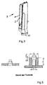
- Figure 2 shows a plan view of a screw dome 3, which in a wave-shaped Section 13 of the component wall 2 is arranged. Furthermore, one is at a distance "r" to the ringdom 3 extending, dashed line shown, the maximum allowable Distance of an actual center of the screw 3 from the desired center represented. Of the Distance “r” is referred to as the allowable center tolerance, which is a measure of the distance between a running in the longitudinal direction of the screw dome actual center axis to the desired center axis is. The size of the respective permissible center tolerance "r” depends on the Size of a component having the rantdom 3 selected.
- the permissible minimum tolerance "r" in Depending on the size of the component sometimes also considerably larger.
- an air intake shaft 9 is shown, which, as stated above Has screw domes, and is used in commercial vehicles of the Applicant.
- the air intake shaft 9, via which the engine combustion air is supplied, is behind the cab arranged and standing, so in "raised” execution, on Cab mounted.
- the air intake shaft 9 has in the lateral region a Air inlet opening 10 and at the bottom of an air outlet opening 11.
- a protective grid (not shown), which in the flow direction in front of the air inlet opening 11th arranged and fixed by means of direct fittings on the air intake shaft 9.
- the air intake shaft has eight Screw dome 3 which are distributed over the circumference of the air inlet opening.
- the protective grid points to the opposite in the assembly of these fferdomen 3 points Through holes on, through which a fastening screw plugged in and Screwing thread-forming screwed into the screw domes.
- the component wall the air intake shaft 9 is at the areas provided for the screwing in such a way Wavy executed and provided with through holes that the screw dome. 3 three in the longitudinal direction of the screw domes spatially spaced from each other areas have, which receive the thread of the fastening screw.
- Air intake shaft 9 Due to the utilization of the inventive concept in the production of a Air intake shaft 9 is thus a safe, suitable even under dynamic load Attachment of the protective grid provided on the air intake shaft 9, the simple and quick to assemble. In particular, for the above Component fitting for plastic components no additional nuts or similar fasteners needed.
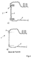
- Figure 4 shows a plastic component 1 with a Component wall 2, in which two ringdome 3 are provided.
- the ringdome 3 serve as Screw holes for the production of a direct screw connection in the plastic component 1.
- the component 1 shown in FIG. 4a is by means of the rotational fusion process been prepared.
- the rotary melting process is in the interior of a Mold at a temperature of about 200 ° C in a heated oven is heated, first introduced a plastic in a powdered state. Subsequently, the mold is placed in a "tumbling" movement such that the plastic on the hot mold wall melts and in this way in the desired shape is brought. Since this manufacturing process with only one works component-forming mold half, receives the outside of the component 1 a defined shape and surface while the inner surface is a largely "unprocessed" Surface has. The preparation of the screw 3 takes place when using the Rotary fusion with the help of appropriately trained pens on the forming mold half are attached.
- the surface of the component wall 2 is after Completion of the actual component forming process initially closed and the ringdom 3 is in a second step by simply piercing the component wall. 2 produced at the corresponding component site. Since the milling process starting from a Component reference point is performed in this manufacturing process Hole pattern tolerances of high quality for the ringdome 3 complied.
- the disadvantage is that the screw dome 3 in this case only a ringdomianae and thus a Has a screw-in length corresponding to the wall thickness of the component wall 2.
- Plastic components such as those used in vehicle construction, material thicknesses of about 3 to 6 mm, which are also subject to large fluctuations, are the screw domes produced by the method described above for a functionally reliable screw connection not suitable.
Landscapes
- Engineering & Computer Science (AREA)
- General Engineering & Computer Science (AREA)
- Mechanical Engineering (AREA)
- Life Sciences & Earth Sciences (AREA)
- Chemical & Material Sciences (AREA)
- Dispersion Chemistry (AREA)
- Wood Science & Technology (AREA)
- Connection Of Plates (AREA)
- Moulds For Moulding Plastics Or The Like (AREA)
- Lining Or Joining Of Plastics Or The Like (AREA)
Abstract
Description
- Fig. 1
- Darstellung eines Schraubdomes in einer wellenförmig ausgebildeten Bauteilwand
- Fig. 2
- Draufsicht auf einen Schraubdom
- Fig. 3
- Luftansaugschacht eines Lastkraftwagens
- Fig. 4
- Darstellung von nach dem Stand der Technik als sackförmige bzw. als durchgängige Kernlöcher ausgeführten Schraubdomen
- Fig. 5
- Darstellung der Bemassung von Einschraub- bzw. Durchgangslöchern

- 1
- Bauteil
- 2
- Bauteilwand
- 3
- Schraubdom
- 4
- Kernlochwandfläche
- 5
- Kerlochwandflächenbereich
- 6
- äußere Oberfläche der Bauteilwand
- 7
- innere Oberfläche der Bauteilwand
- 8
- Deckel
- 9
- Luftansaugschacht
- 10
- Lufteintrittsöffnung
- 11
- Luftaustrittsöffnung
- 12
- Durchgangsloch
- 13
- wellenförmiger Abschnitt
- r
- zulässige Mittenabweichung
Claims (9)
- Bauteilverschraubung in einem zumindest teilweise einen plastischen Werkstoff aufweisenden Bauteil (1) mit einem als sackförmiges oder als durchgängiges Kernloch ausgeführten Schraubdom (3), der eine hohlzylinderförmige Kernlochwandfläche (4) aufweist, und mit einer Schraube, die über ein Außengewinde mit wenigstens einem Gewindegang verfügt und die unter Ausbildung einer schraubenförmigen Kontaktfläche zwischen der Schraube und dem Werkstoff in den Schraubdom (3) einschraubbar ist, dadurch gekennzeichnet, dass die hohlzylinderförmige Kernlochwandfläche (4) des Schraubdoms (3) wenigstens zwei, zumindest teilweise in Längsrichtung des Schraubdomes (3) von einander räumlich beabstandete Kernlochwandflächenbereiche (5) aufweist.
- Bauteilverschraubung nach Anspruch 1, dadurch gekennzeichnet, dass die wenigstens zwei, zumindest teilweise in Längsrichtung des Schraubdomes (3) von einander räumlich beabstandeten Kernlochwandflächenbereiche (5) von Mantelflächen wenigstens zweier Durchgangslöcher (12), die in einer zumindest abschnittsweise wellen- und/oder faltenförmig ausgebildeten Bauteilwand (2) vorgesehen sind, gebildet werden.
- Bauteilverschraubung nach Anspruch 1, dadurch gekennzeichnet, dass die wenigstens zwei, zumindest teilweise in Längsrichtung des Schraubdomes (3) von einander räumlich beabstandeten Kernlochwandflächenbereiche (5) von einer Mantelfläche eines Sackloches und einer Mantelfläche wenigstens eines Durchgangsloches (12) gebildet werden, wobei das Sackloch und das wenigstens eine Durchgangsloch (12) in einer zumindest abschnittsweise wellen- und/oder faltenförmig ausgebildeten Bauteilwand (2) angeordnet sind.
- Bauteilverschraubung nach einem der Ansprüche 1 bis 3, dadurch gekennzeichnet, dass der plastische Werkstoff wenigstens teilweise einen thermoplastischen Kunststoff aufweist.
- Bauteilverschraubung nach einem der Ansprüche 1 bis 4, dadurch gekennzeichnet, dass die hohlzylinderförmige Kernlochwandfläche (4) des Schraubdoms (3) in Längsrichtung über eine Länge verfügt, die wenigstens einem zweifachen Wert eines Außendurchmessers der Schraube entspricht.
- Bauteilverschraubung nach einem der Ansprüche 1 bis 5, dadurch gekennzeichnet, dass der als Sack- oder als Durchgangsloch (12) ausgeführte Schraubdom (3) in Längsrichtung eine Schraubdomtiefe von wenigstens 6 mm aufweist.
- Verfahren zur Herstellung eines als sackförmiges oder als durchgängiges Kernloch ausgeführten, eine hohlzylinderförmige Kernlochwandfläche (4) aufweisenden Schraubdoms (3) in einer Bauteilwand (2) eines Kunststoffbauteils, bei dem das Kunststoffbauteil mittels eines Rotationsschmelzverfahrens, Thermoplastspritzgießens, Heißpressens, Blasverfahrens und/oder mittels eines spanenden Fertigungsverfahrens erzeugt wird, dadurch gekennzeichnet, dass in einen ersten Wandabschnitt der Bauteilwand ein Durchgangsloch (12) mit zwei in gegenüberliegende Oberflächenbereichen des ersten Wandabschnitts befindlichen Lochöffnungen und in wenigstens einen zweiten Wandabschnitt der Bauteilwand ein Durchgangs- (12) oder ein Sackloch mit wenigstens einer in einem Oberflächenbereich des zweiten Wandabschnittes befindlichen Lochöffnung eingebracht werden und dass die Bauteilwand (2) derart geformt wird, dass sich die Lochöffnungen des ersten und des zweiten Wandabschnitts räumlich beabstandet wenigstens teilweise überdecken.
- Verfahren nach Anspruch 7, dadurch gekennzeichnet, dass das Durchgangsloch (12) mittels eines Bohr- oder eines Fräsvorgangs in den ersten Wandabschnitt eingebracht wird.
- Verfahren nach Anspruch 7 oder 8, dadurch gekennzeichnet, dass das Durchgangs- (12) oder das Sackloch mittels eines Bohr- oder eines Fräsvorgangs in den wenigstens einen zweiten Wandabschnitt eingebracht wird.
Priority Applications (1)
| Application Number | Priority Date | Filing Date | Title |
|---|---|---|---|
| PL04024918T PL1528268T3 (pl) | 2003-10-31 | 2004-10-20 | Złącze śrubowe elementu konstrukcyjnego, jak również sposób wytwarzania wgłębienia na śrubę |
Applications Claiming Priority (2)
| Application Number | Priority Date | Filing Date | Title |
|---|---|---|---|
| DE10350887A DE10350887A1 (de) | 2003-10-31 | 2003-10-31 | Bauteilverschraubung sowie Verfahren zur Herstellung eines Schraubdoms |
| DE10350887 | 2003-10-31 |
Publications (2)
| Publication Number | Publication Date |
|---|---|
| EP1528268A1 true EP1528268A1 (de) | 2005-05-04 |
| EP1528268B1 EP1528268B1 (de) | 2007-07-25 |
Family
ID=34399629
Family Applications (1)
| Application Number | Title | Priority Date | Filing Date |
|---|---|---|---|
| EP04024918A Expired - Lifetime EP1528268B1 (de) | 2003-10-31 | 2004-10-20 | Bauteilverschraubung sowie Verfahren zur Herstellung eines Schraubdoms |
Country Status (3)
| Country | Link |
|---|---|
| EP (1) | EP1528268B1 (de) |
| DE (2) | DE10350887A1 (de) |
| PL (1) | PL1528268T3 (de) |
Cited By (1)
| Publication number | Priority date | Publication date | Assignee | Title |
|---|---|---|---|---|
| DE102009053856A1 (de) | 2009-11-19 | 2011-05-26 | Audi Ag | Vorrichtung zum Verbinden zweier Bauteile |
Families Citing this family (3)
| Publication number | Priority date | Publication date | Assignee | Title |
|---|---|---|---|---|
| DE102009015376A1 (de) * | 2009-03-27 | 2010-09-30 | Ejot Gmbh & Co. Kg | Schraubverbindung zur festen Verbindung zweier Baugruppen |
| DE202014103640U1 (de) | 2014-08-05 | 2014-08-21 | Smp Deutschland Gmbh | Schraubdom zum Befestigen eines Bauteils |
| DE102017104384B4 (de) | 2017-03-02 | 2024-01-25 | Lisa Dräxlmaier GmbH | Bauteil mit schraubdom und verfahren zum verbinden eines bauteils |
Citations (4)
| Publication number | Priority date | Publication date | Assignee | Title |
|---|---|---|---|---|
| DE2152089A1 (de) * | 1971-10-19 | 1973-05-03 | Wolfgang Teetz | Knotenpunktmehrbein |
| EP0589399A1 (de) * | 1992-09-21 | 1994-03-30 | HANS SCHRIEVER GmbH & Co. | Selbstfurchende Schraube |
| DE19732615A1 (de) * | 1997-07-29 | 1999-02-04 | Ejot Verbindungstech Gmbh & Co | Befestigungsschraube mit selbstfurchendem Gewinde |
| US6287064B1 (en) * | 1999-12-10 | 2001-09-11 | Western Sky Industries, Inc. | Clip type fastener assembly |
-
2003
- 2003-10-31 DE DE10350887A patent/DE10350887A1/de not_active Withdrawn
-
2004
- 2004-10-20 PL PL04024918T patent/PL1528268T3/pl unknown
- 2004-10-20 DE DE502004004421T patent/DE502004004421D1/de not_active Expired - Lifetime
- 2004-10-20 EP EP04024918A patent/EP1528268B1/de not_active Expired - Lifetime
Patent Citations (4)
| Publication number | Priority date | Publication date | Assignee | Title |
|---|---|---|---|---|
| DE2152089A1 (de) * | 1971-10-19 | 1973-05-03 | Wolfgang Teetz | Knotenpunktmehrbein |
| EP0589399A1 (de) * | 1992-09-21 | 1994-03-30 | HANS SCHRIEVER GmbH & Co. | Selbstfurchende Schraube |
| DE19732615A1 (de) * | 1997-07-29 | 1999-02-04 | Ejot Verbindungstech Gmbh & Co | Befestigungsschraube mit selbstfurchendem Gewinde |
| US6287064B1 (en) * | 1999-12-10 | 2001-09-11 | Western Sky Industries, Inc. | Clip type fastener assembly |
Cited By (1)
| Publication number | Priority date | Publication date | Assignee | Title |
|---|---|---|---|---|
| DE102009053856A1 (de) | 2009-11-19 | 2011-05-26 | Audi Ag | Vorrichtung zum Verbinden zweier Bauteile |
Also Published As
| Publication number | Publication date |
|---|---|
| DE502004004421D1 (de) | 2007-09-06 |
| DE10350887A1 (de) | 2005-05-25 |
| EP1528268B1 (de) | 2007-07-25 |
| PL1528268T3 (pl) | 2007-12-31 |
Similar Documents
| Publication | Publication Date | Title |
|---|---|---|
| EP2136088B1 (de) | Verbindungselement mit einer Schraube und einer daran unverlierbar angeordneten Hülse | |
| EP0678679A1 (de) | Ein durch Nieten in ein Blechteil einsetzbares Element | |
| EP2004453A1 (de) | Crashbox und dämpfungsanordnung mit crashbox | |
| WO2021043833A1 (de) | Dichtungsanordnung, batterie- oder steuerungskasten, kraftfahrzeug und verfahren zur herstellung einer dichtungsanordnung | |
| DE202009014886U1 (de) | Kugelzapfen | |
| EP1753988B1 (de) | Trägerrahmendichtung mit befestigungsmitteln zur abdichtung von motorbauteilen | |
| EP1503096B1 (de) | Halteelement zur Fixierung wenigstens eines Lagers | |
| EP1528268B1 (de) | Bauteilverschraubung sowie Verfahren zur Herstellung eines Schraubdoms | |
| EP1642037B1 (de) | Lageranordnung für ein kraftfahrzeug | |
| DE10020218B4 (de) | Montageeinheit aus einem Bauteil und mindestens einer gewindeformenden Schraube | |
| DE60027628T2 (de) | Unverlierbares Befestigungselement und Verfahren zu seiner Montage | |
| DE102015012591A1 (de) | Rohrverbindungsanordnung und Rohrverbindung zweier Rohre | |
| WO2012013352A1 (de) | Vorformling für ein innenverkleidungsteil eines fahrzeuges und innenverkleidungsteil | |
| EP2948656B1 (de) | Metallblech-flachdichtungslage sowie verfahren zu ihrer herstellung | |
| EP0528104A1 (de) | Gehäuseverschlussdeckel | |
| DE202019104970U1 (de) | Kugelbolzen | |
| EP4538550B1 (de) | Additiv hergestelltes bauteil, bauteilverbund mit dem bauteil, herstellungsverfahren des bauteils und verbindungsverfahren zur herstellung des bauteilverbunds | |
| EP4039992B1 (de) | Verbindungsteil und verfahren zur herstellung eines verbindungteils | |
| EP1794461A1 (de) | Niet- oder schraubverbindung eines kunststoffteils mit einem weiteren teil | |
| DE102024119189A1 (de) | Gehäuse für einen elektrischen Energiespeicher eines Kraftwagens, Verfahren zum Herstellen eines Gehäuses, Energiespeicher mit einem Gehäuse sowie Kraftwagen mit einem Energiespeicher | |
| DE102023122430A1 (de) | Befestigungselement, Befestigungsanordnung und Verfahren zum Befestigen | |
| DE102004018800A1 (de) | Montageeinheit mit einer Nietverbindung | |
| DE102018210893A1 (de) | Schraubelement und Verfahren zum Herstellen eines solchen Schraubelements | |
| DE102023205273A1 (de) | Vorrichtung zum Ausgleichen von Toleranzen | |
| DE102024116234A1 (de) | Schraubverbindung für einen Bauteilverbund sowie Verfahren zur Herstellung einer solchen Schraubverbindung |
Legal Events
| Date | Code | Title | Description |
|---|---|---|---|
| PUAI | Public reference made under article 153(3) epc to a published international application that has entered the european phase |
Free format text: ORIGINAL CODE: 0009012 |
|
| AK | Designated contracting states |
Kind code of ref document: A1 Designated state(s): AT BE BG CH CY CZ DE DK EE ES FI FR GB GR HU IE IT LI LU MC NL PL PT RO SE SI SK TR |
|
| AX | Request for extension of the european patent |
Extension state: AL HR LT LV MK |
|
| 17P | Request for examination filed |
Effective date: 20050603 |
|
| AKX | Designation fees paid |
Designated state(s): DE FR IT PL SE TR |
|
| GRAP | Despatch of communication of intention to grant a patent |
Free format text: ORIGINAL CODE: EPIDOSNIGR1 |
|
| GRAS | Grant fee paid |
Free format text: ORIGINAL CODE: EPIDOSNIGR3 |
|
| GRAA | (expected) grant |
Free format text: ORIGINAL CODE: 0009210 |
|
| AK | Designated contracting states |
Kind code of ref document: B1 Designated state(s): DE FR IT PL SE TR |
|
| REF | Corresponds to: |
Ref document number: 502004004421 Country of ref document: DE Date of ref document: 20070906 Kind code of ref document: P |
|
| REG | Reference to a national code |
Ref country code: SE Ref legal event code: TRGR |
|
| REG | Reference to a national code |
Ref country code: PL Ref legal event code: T3 |
|
| ET | Fr: translation filed | ||
| PLBE | No opposition filed within time limit |
Free format text: ORIGINAL CODE: 0009261 |
|
| STAA | Information on the status of an ep patent application or granted ep patent |
Free format text: STATUS: NO OPPOSITION FILED WITHIN TIME LIMIT |
|
| 26N | No opposition filed |
Effective date: 20080428 |
|
| REG | Reference to a national code |
Ref country code: FR Ref legal event code: CD |
|
| REG | Reference to a national code |
Ref country code: DE Ref legal event code: R081 Ref document number: 502004004421 Country of ref document: DE Owner name: MAN TRUCK & BUS AG, DE Free format text: FORMER OWNER: MAN NUTZFAHRZEUGE AG, 80995 MUENCHEN, DE Effective date: 20110518 |
|
| REG | Reference to a national code |
Ref country code: FR Ref legal event code: PLFP Year of fee payment: 12 |
|
| REG | Reference to a national code |
Ref country code: FR Ref legal event code: PLFP Year of fee payment: 13 |
|
| REG | Reference to a national code |
Ref country code: FR Ref legal event code: PLFP Year of fee payment: 14 |
|
| REG | Reference to a national code |
Ref country code: FR Ref legal event code: PLFP Year of fee payment: 15 |
|
| REG | Reference to a national code |
Ref country code: DE Ref legal event code: R081 Ref document number: 502004004421 Country of ref document: DE Owner name: MAN TRUCK & BUS SE, DE Free format text: FORMER OWNER: MAN TRUCK & BUS AG, 80995 MUENCHEN, DE |
|
| PGFP | Annual fee paid to national office [announced via postgrant information from national office to epo] |
Ref country code: TR Payment date: 20231009 Year of fee payment: 20 Ref country code: SE Payment date: 20231023 Year of fee payment: 20 Ref country code: IT Payment date: 20231024 Year of fee payment: 20 Ref country code: FR Payment date: 20231026 Year of fee payment: 20 Ref country code: DE Payment date: 20231027 Year of fee payment: 20 |
|
| PGFP | Annual fee paid to national office [announced via postgrant information from national office to epo] |
Ref country code: PL Payment date: 20231011 Year of fee payment: 20 |
|
| REG | Reference to a national code |
Ref country code: DE Ref legal event code: R071 Ref document number: 502004004421 Country of ref document: DE |
|
| REG | Reference to a national code |
Ref country code: SE Ref legal event code: EUG |