EP1528256A1 - Variable displacement compressor - Google Patents
Variable displacement compressor Download PDFInfo
- Publication number
- EP1528256A1 EP1528256A1 EP03784588A EP03784588A EP1528256A1 EP 1528256 A1 EP1528256 A1 EP 1528256A1 EP 03784588 A EP03784588 A EP 03784588A EP 03784588 A EP03784588 A EP 03784588A EP 1528256 A1 EP1528256 A1 EP 1528256A1
- Authority
- EP
- European Patent Office
- Prior art keywords
- rotor
- plane
- variable displacement
- plate
- swash
- Prior art date
- Legal status (The legal status is an assumption and is not a legal conclusion. Google has not performed a legal analysis and makes no representation as to the accuracy of the status listed.)
- Withdrawn
Links
Images




Classifications
-
- F—MECHANICAL ENGINEERING; LIGHTING; HEATING; WEAPONS; BLASTING
- F04—POSITIVE - DISPLACEMENT MACHINES FOR LIQUIDS; PUMPS FOR LIQUIDS OR ELASTIC FLUIDS
- F04B—POSITIVE-DISPLACEMENT MACHINES FOR LIQUIDS; PUMPS
- F04B27/00—Multi-cylinder pumps specially adapted for elastic fluids and characterised by number or arrangement of cylinders
- F04B27/08—Multi-cylinder pumps specially adapted for elastic fluids and characterised by number or arrangement of cylinders having cylinders coaxial with, or parallel or inclined to, main shaft axis
- F04B27/10—Multi-cylinder pumps specially adapted for elastic fluids and characterised by number or arrangement of cylinders having cylinders coaxial with, or parallel or inclined to, main shaft axis having stationary cylinders
- F04B27/1036—Component parts, details, e.g. sealings, lubrication
- F04B27/1054—Actuating elements
- F04B27/1072—Pivot mechanisms
Definitions
- a piston is contained in each of a plurality of cylinder bores defined in a housing.
- a rotor is provided to a drive shaft that is rotatably supported by the housing. The rotor rotates integrally with the drive shaft.
- a cam plate (swash plate) is supported slidably and tiltably by the drive shaft.
- a hinge mechanism is provided between the rotor and the cam plate. The rotary motion of the drive shaft is converted into the reciprocating motion of the pistons through the rotor, the hinge mechanism, and the cam plate. Accordingly, the compression of a refrigerant gas is performed.
- the hinge mechanism guides the cam plate so that the cam plate slides on the drive shaft while tilting. According to an inclination angle of the cam plate, the stroke of the pistons, that is, the displacement of the variable displacement compressor is changed.
- Cylinder bores 22 are formed in the above-mentioned cylinder block 11.
- the cylinder bores 22 are arranged at equal angular intervals around the axis L of the drive shaft 16.
- the cylinder bores 22 are extended along with the axis L of the drive shaft 16.
- a single-headed piston 23 is accommodated in each of the cylinder bores 22.
- Each piston 22 reciprocates in the corresponding cylinder bore 22.
- Front and back openings of each of the cylinder bores 22 are blocked by a front end face 13a of a valve and port assembly 13 and a corresponding one of the pistons 23, respectively, and a compression chamber 24, the volume of which changes according to the reciprocating motion of the corresponding one of the pistons 23, is provided in that one of the cylinder bores 22.
- Cylinder faces 45b and 46b which are convex surfaces, are formed at ends of the above-mentioned swash-plate-side protrusions 45 and 46, respectively.
- the main axis S of the respective cylindrical faces 45b and 46b is perpendicular to the side faces 45a and 46a.
- the ends of the respective swash-plate-side protrusions 45 and 46 slidably abut against the cam face 47a of the corresponding cam portion 47 through the cylindrical faces 45b and 46b. Therefore, the axial load that acts on the swash plate 18 because of compression reaction force etc. is received by the cam face 47a of the cam portion 47 through the cylindrical faces 45b and 46b of the swash-plate-side protrusions 45 and 46.
- a protruding portion 73 is provided in a position corresponding to the engaging groove 70.
- the protruding portion 73 transmits power to a side face 71a of the wall portion 71 in the swash plate 18 with a side face 73a in the state of being inserted and engaged between the side faces (wall surfaces) 71a and 72a of the wall portions 71 and 72, which face each other (when the rotational direction of the drive shaft 16 is the direction shown by the arrow R).
- the protruding portion 73 transmits power to the side face 72a of the wall portion 72 in the swash plate 18 with a side face 73b.
Landscapes
- Engineering & Computer Science (AREA)
- Mechanical Engineering (AREA)
- General Engineering & Computer Science (AREA)
- Compressors, Vaccum Pumps And Other Relevant Systems (AREA)
Abstract
A rotor is fixed to a drive shaft supported by a
housing. A swash plate is supported slidably and tiltably by
the drive shaft. A hinge mechanism is provided between the
rotor and swash plate. The hinge mechanism comprises two
rotor-side protrusions provided in the rotor and a protruding
portion provided in the swash plate. The protruding portion
is inserted between side faces in which the two rotor-side
protrusions face each other, and perform power transfer
between the rotor and swash plate by two-dimensionally
abutting against a side face of one of the rotor-side
protrusions. A concavity is provided in the side face of the
rotor-side protrusion. Therefore, an area of the side face of
the rotor-side protrusion abutting on the side face of the
swash-plate-side protrusion decreases, and smooth change of
discharge volume is achieved while controlling processing
cost.
Description
The present invention relates to a variable
displacement compressor incorporated in, for example, a
refrigeration circuit of a vehicle air conditioner.
A typical variable displacement compressor is disclosed
in, for example, Japanese Laid-Open Patent Publication No.
2001-304102.
That is, a piston is contained in each of a plurality
of cylinder bores defined in a housing. A rotor is provided
to a drive shaft that is rotatably supported by the housing.
The rotor rotates integrally with the drive shaft. A cam
plate (swash plate) is supported slidably and tiltably by the
drive shaft. A hinge mechanism is provided between the rotor
and the cam plate. The rotary motion of the drive shaft is
converted into the reciprocating motion of the pistons
through the rotor, the hinge mechanism, and the cam plate.
Accordingly, the compression of a refrigerant gas is
performed. The hinge mechanism guides the cam plate so that
the cam plate slides on the drive shaft while tilting.
According to an inclination angle of the cam plate, the
stroke of the pistons, that is, the displacement of the
variable displacement compressor is changed.
The above-mentioned hinge mechanism comprises two arms
extending toward the rotor from the cam plate, and a
protruding portion that extends toward the cam plate from the
rotor and is inserted between facing wall surfaces of the two
arms. This protruding portion has a couple of side faces,
which face the facing wall surfaces of the arms,
respectively. In a state where the protruding portion
performs surface contact to, and is pressed on, one wall
surface of the arms, power transfer between the rotor and the
cam plate is performed. Hence, at the time of tilting of the
cam plate, one of the arms is slid to the protruding portion
while maintaining the state where a wall surface of one of
the arms and one side face of the protruding portion perform
surface contact.
In the above-mentioned hinge mechanism, it is desirable
that the arms slide on the protruding portion in the state
where the arms maitain surface contact to the protruding
portion so as to attain smooth displacement change in the
variable displacement compressor, i.e., smooth tilting of the
cam plate. That is, if the cam plate is tilted by an offset
action from an axial load resulting from a compression
reaction force to make the protruding portion pry up from
between the two arms, sliding friction between the arms and
the protruding portion becomes large. Hence, there arise
problems such as early abrasion of the arms and the
protruding portion, that is, a durability drop in the hinge
mechanism, and deterioration in displacement controllability
of the variable displacement compressor caused by the hinge
mechanism not operating smoothly.
It is necessary to make play of the protruding portion
between both arms as small as possible within a range where
smooth motion of the protruding portion to the arms is not
impeded, so as to prevent the protruding portion from being
pried from between the two arms. For that purpose, it is
necessary to set a distance between the facing wall surfaces
of the arms in the cam plate and a distance between the side
faces of the protruding portion in the rotor, respectively,
with high accuracy. Hence, it is necessary to perform the
finish-machining of the facing wall surfaces of the arms and
the side faces of the protruding portion, respectively, with
high accuracy. However, such highly accurate finish-machining
becomes a factor which raises the manufacturing cost of the
compressor.
The present invention aims at providing a variable
displacement compressor that achieves smooth displacement
change while reducing machining costs.
In order to achieve the above-described object, the
present invention provides a variable displacement compressor,
in which a piston is accommodated in a cylinder bore in a
housing, and a drive shaft is rotatably supported by the
housing. A rotor is provided to the drive shaft such that the
rotor rotates integrally with the drive shaft. A cam plate is
supported slidably and tiltably by the drive shaft. A hinge
mechanism is provided between the rotor and the cam plate.
Rotation of the drive shaft is converted into reciprocation
of the piston through the rotor, the hinge mechanism, and the
cam plate. The cam plate is slid on the drive shaft by the
guidance of the hinge mechanism to change the displacement of
the compressor. The hinge mechanism includes a first hinge
portion extending from a first member toward a second member.
The first member is one of the rotor and the cam plate. The
second member is the other one of the rotor and the cam plate.
The second hinge portion extends from the second member
toward the first member. One of the first hinge and the
second hinge portions includes at least two wall portions,
and the other is a protruding portion inserted between two
wall portions. The wall portions have facing surfaces facing
each other. The protruding portion has a couple of facing
surfaces each of which faces the facing surface of one of the
wall portions. One of the facing surfaces of the protruding
portion two-dimensionally abuts against one of the facing
surfaces of the wall portions such that power is transferred
between the rotor and the cam plate. A thin-walled portion is
provided in at least one of the facing surfaces.
Hereafter, variable displacement compressors according
to first to fourth embodiments of the present invention will
be described. Each compressor is part of a refrigeration
circuit of a vehicle air conditioner as will be explained. In
addition, in the second to fourth embodiments, only the
points different from those of the first embodiment will be
explained. The same numerals will be assigned to the same or
corresponding members, and their explanation will be omitted.
First, the first embodiment will be explained with
reference to FIGS. 1 to 4.
FIG. 1 shows a vertical section of a variable
displacement compressor (hereafter, simply a compressor). In
FIG. 1, it is assumed that the left-hand side is the front of
the compressor and the right-hand side is the back of the
compressor.
As shown in FIG. 1, a housing of the compressor
(compressor housing) comprises a cylinder block 11, a front
housing member 12 fixed to the front end of the cylinder
block 11, and a rear housing member 14 fixed to the rear edge
of the cylinder block 11 through a valve and port assembly
(valve assembly) 13.
Between the cylinder block 11 and front housing member
12, a crank chamber 15 is defined. A drive shaft 16 is
rotatably supported through the crank chamber 15 by the
cylinder block 11 and front housing member 12. An engine E
that is a drive source of a vehicle is coupled to the drive
shaft 16 through a clutchless (constant power transfer type)
power transmission mechanism PT. Hence, at the time of the
operation of the engine E, the drive shaft 16 is constantly
rotated in response to the supply of power from the engine E.
A substantially disk-shaped rotor 17 is fixed to the
drive shaft 16 in the above-mentioned crank chamber 15 so
that the rotor 17 rotates integrally with the drive shaft 16.
A swash plate 18 as a cam plate having a substantially disk-like
shape is contained in the crank chamber 15. Either the
rotor 17 or the swash plate 18 is equivalent to the first
member, and the other of the rotor 17 and swash plate 18 is
equivalent to the second member. An insertion hole 20 extends
through the center portion of the swash plate 18. The drive
shaft 16 is inserted in the insertion hole 20, and the swash
plate 18 is supported by the drive shaft 16 slidably and
tiltably.
A hinge mechanism 19 is provided between the above-mentioned
rotor 17 and swash plate 18. The hinge mechanism 19
permits the swash plate 18 to slide on the drive shaft 16
along with an axis L of the drive shaft 16 while
synchronously revolving the swash plate 18 with the rotor 17
and drive shaft 16.
Cylinder bores 22 are formed in the above-mentioned
cylinder block 11. The cylinder bores 22 are arranged at
equal angular intervals around the axis L of the drive shaft
16. The cylinder bores 22 are extended along with the axis L
of the drive shaft 16. A single-headed piston 23 is
accommodated in each of the cylinder bores 22. Each piston 22
reciprocates in the corresponding cylinder bore 22. Front and
back openings of each of the cylinder bores 22 are blocked by
a front end face 13a of a valve and port assembly 13 and a
corresponding one of the pistons 23, respectively, and a
compression chamber 24, the volume of which changes according
to the reciprocating motion of the corresponding one of the
pistons 23, is provided in that one of the cylinder bores 22.
Each piston 23 is engaged to an outer circumferential portion
of the swash plate 18 through a couple of shoes 25, which are
hemispherical. Hence, the rotary motion of the swash plate 18
accompanying rotation of the drive shaft 16 is converted into
linear reciprocation of each piston 23 through the shoes 25.
Between the valve and port assembly 13 and the rear
housing member 14, a suction chamber 26 and a discharge
chamber 27 are defined respectively. The valve and port
assembly 13 has a suction port 28, a suction valve 29, a
discharge port 30, and a discharge valve 31 respectively
corresponding to each of the cylinder bores 22. Refrigerant
gas from the suction chamber 26 is drawn into the compression
chamber 24 through the suction port 28 and suction valve 29
in connection with each of the pistons 23 moving toward a
bottom dead center position from a top dead center position.
The refrigerant gas drawn into each compression chamber 24 is
discharged into the discharge chamber 27 through the
corresponding discharge port 30 and the corresponding
discharge valve 31 after being compressed to a predetermined
pressure in connection with the corresponding piston 23
moving toward the top dead center position from the bottom
dead center position.
As shown in FIG. 1, a bleed passage 32, a supply
passage 33, and a control valve 34 are provided in the above-mentioned
compressor housing. The bleed passage 32 connects
the crank chamber 15 with the suction chamber 26. The supply
passage 33 connects the discharge chamber 27 with the crank
chamber 15. The above-mentioned control valve 34 consisting
of a solenoid valve is arranged in the supply passage 33.
Then, the balance of an introduction amount of a high
pressure refrigerant gas to the crank chamber 15 through the
supply passage 33 from the discharge chamber 27, and a
derived amount of a gas into the suction chamber 26 through
the bleed passage 32 from the crank chamber 15 is controlled
by adjusting the opening of the above-mentioned control valve
34 by electric supply control to the control valve 34 from
the outside. Accordingly, the internal pressure of the crank
chamber 15 is determined. As a result of changing the
difference between the internal pressure of the crank chamber
15, and the internal pressure of the compression chambers 24
according to the change of the internal pressure of the crank
chamber 15 and changing the inclination angle of the swash
plate 18 according to the internal pressure change of the
crank chamber 15, the stroke of the pistons 23, i.e., the
displacement of the compressor is adjusted. In addition, an
inclination angle of the swash plate 18 is expressed by an
angle to a plane orthogonal to the axis L of the drive shaft
16.
For example, when the opening of the above-mentioned
control valve 34 decreases, the internal pressure of the
crank chamber 15 decreases. Then, the inclination angle of
the swash plate 18 increases, the stroke of the pistons 23
increases, and the displacement of the compressor increases.
The maximum inclination angle of the swash plate 18 is
regulated by a protrusion (maximum inclination angle
regulating portion) 18a abutting against the rear face of the
rotor 17, the protrusion 18a being provided in front of the
swash plate 18.
On the contrary, when a valve opening of the above-mentioned
control valve 34 increases, the internal pressure
of the crank chamber 15 rises. Then, the inclination angle of
the swash plate 18 decreases, the stroke of the pistons 23
decreases, and the displacement of the compressor decreases.
The minimum inclination angle of the swash plate 18 is
defined by a minimum inclination angle defining portion 35
provided on the drive shaft 16.
The above-mentioned minimum inclination angle defining
portion 35 comprises a coil spring 35a which is wound around
the drive shaft 16, and a Circlip (snap ring) 35b which is
fixed to the drive shaft 16 and functions as a spring seat
for the coil spring 35a. The coil spring 35a urges the rear
center portion of the swash plate 18 toward the front of the
compressor, that is, in the direction where the inclination
angle of the swash plate 18 increases.
In the above-mentioned drive shaft 16, the coil spring
36 is wound between the rear face of the rotor 17, and the
front face of the swash plate 18. The coil spring 36 urges
the front center portion of the swash plate 18 toward the
rear of the compressor, that is, in the direction where the
inclination angle of the swash plate 18 decreases. The urging
force of the coil spring 36 and the urging force of the coil
spring 35a of the minimum inclination angle defining portion
35 mentioned above, participate in the decision for the
inclination angle of the swash plate 18.
As shown in FIG. 1, the swash plate 18 has a top dead
center corresponding region TDC which locates the pistons 23
at the top dead center positions. The top dead center
corresponding region TDC includes the central points of
spherical surfaces of both of the shoes 25 corresponding to
each of the pistons 23 at the top dead center position. As
shown in FIGS. 1 and 2, an engaging groove 41 is formed in a
position, facing the top dead center corresponding region TDC
of the swash plate 18, in the rear face of the above-mentioned
rotor 17. The engaging groove 41 is formed by the
two rotor- side protrusions 42 and 43 extending toward the
swash plate 18 from the rear face of the rotor 17. Both
rotor- side protrusions 42 and 43 are provided in advancing
and trailing positions in the rotation direction (the
direction shown by the arrow R of FIG. 2, or the reverse
direction thereof) of the rotor 17.
The two rotor- side protrusions 42 and 43 function as
two wall portions extending toward the swash plate 18 from
the rotor 17 so as to form the above-mentioned engaging
groove 41. The rotor- side protrusions 42 and 43 have side
faces (facing surfaces) 42a and 43a which mutually face each
other in the engaging groove 41.
As shown in FIGS. 1 and 3, in the front face of the
above-mentioned swash plate 18, a protruding portion 44
extending toward the rotor 17 is provided in a portion facing
the above-mentioned engaging groove 41. The protruding
portion 44 includes two swash-plate- side protrusions 45 and
46. Both swash-plate- side protrusions 45 and 46 are located
in symmetric positions in the advancing and trailing sides of
the rotation direction over the top dead center corresponding
region TDC in the rotation direction (the direction shown by
the arrow R of FIG. 3, or the reverse direction thereof) of
the drive shaft 16. In other words, the protruding portion 44
is made in the hollow structure where the two swash-plate- side
protrusions 45 and 46 are left in both sides for weight
saving in the swash plate 18.
In this embodiment, either the above-mentioned rotor- side
protrusions 42 and 43 or the above-mentioned protruding
portion 44 is equivalent to the first hinge portion, and
another of the above-mentioned rotor- side protrusions 42 and
43, and the above-mentioned protruding portion 44 is
equivalent to the second hinge portion.
Both the above-mentioned swash-plate- side protrusions
45 and 46 are located in the engaging groove 41 from those
end sides, respectively. Both the swash-plate- side
protrusions 45 and 46 have side faces 45a and 46a which face
away from each other. The side faces (facing surfaces) 45a
and 45b can two-dimensionally abut against the side faces 42a
and 43a of the rotor- side protrusions 42 and 43 respectively.
When the above-mentioned drive shaft 16 rotates in the
direction shown by the arrow R, the rotational force of the
rotor 17 is transmitted to the swash plate 18 through the
side face 42a of the rotor-side protrusion 42, which becomes
a power transfer side, and the side face 45a of the swash-plate-side
protrusion 45 which abuts against the side face
42a. On the contrary, when the drive shaft 16 rotates in the
direction reverse to the direction shown by the arrow R, the
rotational force of the rotor 17 is transmitted to the swash
plate 18 through the side face 43a of the rotor-side
protrusion 43, which becomes a power transfer side, and the
side face 46a of the swash-plate-side protrusion 46 which
abuts against the side face 43a.
That is, in order to increase flexibility, the
compressor of this embodiment is constituted to be suitably
applied to a vehicle engine regardless of the rotation
direction of the engine. In other words, the compressor is
constituted to be applied to the engine regardless of whether
the rotation direction of the drive shaft 16 demanded by the
user is the direction shown by the arrow R or the direction
reverse to that shown by the arrow R. Hence, for example, the
hinge mechanism 19 is constituted so as to form a symmetrical
shape in the advancing and trailing sides in the rotation
direction over the corresponding top dead center region TDC
in the rotation direction of the drive shaft 16.
In the above-mentioned engaging groove 41, a cam
portion 47 projects as an axial load receiving portion in the
base of respective rotor- side protrusions 42 and 43. In each
cam portion 47, a cam face 47a, which tilts toward its back
side approaching the axis L of the drive shaft 16, is formed
in a rear end face that faces the swash plate 18.
Cylinder faces 45b and 46b, which are convex surfaces,
are formed at ends of the above-mentioned swash-plate- side
protrusions 45 and 46, respectively. The main axis S of the
respective cylindrical faces 45b and 46b is perpendicular to
the side faces 45a and 46a. The ends of the respective swash-plate- side
protrusions 45 and 46 slidably abut against the
cam face 47a of the corresponding cam portion 47 through the
cylindrical faces 45b and 46b. Therefore, the axial load that
acts on the swash plate 18 because of compression reaction
force etc. is received by the cam face 47a of the cam portion
47 through the cylindrical faces 45b and 46b of the swash-plate- side
protrusions 45 and 46.
Then, for example, when the above-mentioned compressor
increases its own displacement, the swash plate 18 is rotated
in the clockwise direction as viewed in FIG. 1 with the main
axis S of the cylindrical faces 45b and 46b of the swash-plate- side
protrusions 45 and 46 as the center. At the same
time, the hinge mechanism 19 guides the increase of the
inclination angle of the swash plate 18 by the ends of the
swash-plate- side protrusions 45 and 46 being moved in the
direction of being separated from the drive shaft 16 on the
cam face 47a of the cam portion 47.
On the contrary, when the above-mentioned compressor
decrease its own displacement, the swash plate 18 is rotated
in the counterclockwise direction of FIG. 1 with the main
axis S of the cylindrical faces 45b and 46b as the center. At
the same time, the hinge mechanism 19 guides the decrease of
the inclination angle of the swash plate 18 by the ends of
the swash-plate- side protrusions 45 and 46 being moved in the
direction of approach towards the drive shaft 16 on the cam
face 47a of the cam portion 47.
The above-mentioned hinge mechanism 19 permits the
change of the inclination angle of the swash plate 18 while
maintaining power transfer to the swash plate 18 from the
rotor 17 by enabling the contact engagement of the side faces
42a and 43a of the rotor- side protrusions 42 and 43, and the
side faces 45a and 46a of the swash-plate- side protrusions 45
and 46 two-dimensionally. Therefore, when the rotation
direction of the drive shaft 16 is as shown by the arrow R,
the pressure slide of the side face 42a of the rotor-side
protrusion 42 and the side face 45a of the swash-plate-side
protrusion 45, which bear power transfer, follows the change
of the inclination angle of the swash plate 18. On the
contrary, when the rotation direction of the drive shaft 16
is reverse to the direction shown by the arrow R, the
pressure slide of the side face 43a of the rotor-side
protrusion 43 and the side face 46a of the swash-plate-side
protrusion 46, which bear power transfer, follows the change
of the inclination angle of the swash plate 18.
In the above-mentioned hinge mechanism 19, the cam face
47a of the cam portion 47 and the cylindrical faces 45b and
46b of the swash-plate- side protrusions 45 and 46 are
subjected to a hardening treatment for increasing the
durability in mutual pressure slide. The hardening treatment
is performed, for example, by high frequency hardening. Areas
where the hardening treatment is applied in the hinge
mechanism 19 are the dotted areas 50 and 51 shown in FIGS. 1
to 3. That is, the hardening treatment is applied to limited
parts of the cam face 47a of the cam portion 47 and the
cylindrical faces 45b and 46b of the swash-plate- side
protrusions 45 and 46 in the hinge mechanism 19.
The cam face 47a of the above-mentioned cam portion 47,
side faces 42a and 43a of the rotor- side protrusions 42 and
43, side faces 45a and 46a of the swash-plate- side
protrusions 45 and 46, and cylindrical faces 45b and 46b are
covered with coating films of a solid lubricant. As the solid
lubricant, for example, a fluorocarbon resin such as
polytetrafluoroethylene, molybdenum disulfide, etc. is
suitable. It is possible to decrease frictional resistance
and to make the tilt of the swash plate 18 smooth at the time
of the displacement change, by forming coating films on the
respective sliding surfaces (cam face 47a, side faces 42a and
43a, side faces 45a and 46a, cylindrical faces 45b and 46b).
The above-mentioned swash plate 18 is made to tilt in a
direction different from the direction at the time of
displacement change since the protruding portion 44 in the
engaging groove 41 is pried upward by an offset action of the
axial load resulting from a compression reaction force.
In further detailed explanation, as shown in FIG. 3,
supposing that the rotational direction of the above-mentioned
drive shaft 16 is the direction shown by the arrow
R. In addition, assume that the semicircle portion of the
swash plate 18 on the compression stroke side, that is, the
semicircle portion on the left-hand side of FIG. 3 whose
border is an imaginary plane H including the corresponding
top dead center region TDC and the axis L of the drive shaft
16 receives a reaction force, pushing the swash plate 18
forward from the piston 23, because of the compression of a
refrigerant gas. In addition, the semicircle portion of the
swash plate 18 on the charging stroke side, that is, the
semicircle portion in the right-hand side of FIG. 3 whose
border is the plane H receives a reaction force, pulling the
swash plate 18 back from the piston 23, because of the
inhalation of the refrigerant gas.
Therefore, the above-mentioned swash plate 18 is tilted
in the clockwise direction of FIG. 3, that is, a direction
different from the direction at the time of displacement
change since the side faces 45a and 46a of the swash-plate- side
protrusions 45 and 46 are tilted against the side faces
42a and 43a of the rotor- side protrusions 42 and 43 which
face the side faces 45a and 46a.
As mentioned in "Background of the Invention", in order
to control the tilt of the above-mentioned swash plate 18 in
the direction different from the direction at the time of
displacement change, in other words, the prying of the
protruding portion 44 in the engaging groove 41, it is
necessary to make the play of the protruding portion 44
between the two rotor- side protrusions 42 and 43 small. The
play of this protruding portion 44 is determined by a
clearance which is a value obtained by subtracting a distance
Y between mutually parallel side faces 45a and 46a (refer to
FIG. 3) of two swash-plate- side protrusions 45 and 46, which
constitutes the protruding portion 44, from a distance X
between mutually parallel side faces 42a and 43a (refer to
FIG. 2) of two rotor- side protrusions 42 and 43.
In this embodiment, the above-mentioned clearance (X-Y)
is set in an optimum range of 0.01 to 0.20 mm, or more
preferably, in a rage of 0.03 to 0.11 mm. Namely, if the
clearance (X-Y) is too small, the operation of the hinge
mechanism 19 easily reaches a difficult status under the
influence of dimensional tolerances, thermal expansion of
the rotor 17 and swash plate 18, etc. In addition, when the
clearance (X-Y) is too large, there arises a problem in that
the protruding portion 44 pries within the engaging groove 41.
Therefore, it can be said that the setting range of the
clearance (X-Y) mentioned above is a suitable dimensional
range for the compatibility of the prevention of prying of
the protruding portion 44 in the engaging groove 41 and the
prevention of a malfunction of the hinge mechanism 19
resulting from an excessively small clearance (X-Y).
Chamfer processing is given to salient portions 45c and
46c formed by joints of the side faces 45a and 46a and
cylindrical faces 45b and 46b in the ends of the above-mentioned
swash-plate- side protrusions 45 and 46. The swash
plate 18 is produced by casting and the chamfering of the
salient portions 45c and 46c of the swash-plate- side
protrusions 45 and 46, which is so-called material chamfering
concurrently performed at the time of casting of the swash
plate 18.
As shown in FIGS. 1 and 2, concavities 61 and 62 as
thin-walled portions are formed in the side faces 42a and 43a
of the respective rotor- side protrusions 42 and 43 inside the
above-mentioned engaging groove 41. That is, the side faces
42a and 43a of the respective rotor- side protrusions 42 and
43 comprise regions (sliding surfaces 42a-1 and 43a-1), which
enables abutting engagement with the side faces 45a and 46a
of the swash-plate- side protrusions 45 and 46, which face,
two-dimensionally, and non-sliding surfaces 42a-2 and 43a-2
located inside the concavities 61 and 62. As for the side
faces 42a and 43a of the respective rotor- side protrusions 42
and 43, by the concavities 61 and 62 being formed, areas of
the sliding surfaces 42a-1 and 43a-1 become smaller, for
example, in comparison with the case where the concavities 61
and 62 are not provided.
The concavities 61 and 62 inside the above-mentioned
engaging groove 41 are provided adjacently to the cam portion
47 in the base of the corresponding rotor- side protrusions 42
and 43. The concavities 61 and 62 extend in a groove-like
shape along the direction the cam face 47a extends, that is,
along a slide locus on the cam face 47a of the ends of the
swash-plate- side protrusions 45 and 46 at the time of
displacement change. The non-sliding surfaces 42a-2 and 43a-2
inside the concavities 61 and 62 are continued to the cam
face 47a of the cam portion 47.
Therefore, joints (reentrant portions 61a and 62a) of
the side faces 42a and 43a of the above-mentioned rotor- side
protrusions 42 and 43, and the cam face 47a of the cam
portion 47 perpendicular to the side faces 42a and 43a (in
detail, the sliding surfaces 42a-1 and 43a-1) are located
respectively in positions which enter into the concavities 61
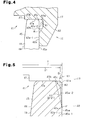
and 62. That is, as shown in FIG. 4, the reentrant portions
61a and 62a which are joints of the side faces 42a and 43a of
the rotor- side protrusions 42 and 43, and the cam face 47a of
the cam portion 47 are relieved from the ends of the swash-plate- side
protrusions 45 and 46 by the formation of the
concavities 61 and 62 to the side faces 42a and 43a.
The reentrant portions 61a and 62a inside the above-mentioned
concavities 61 and 62 are formed in the shape of a
concave surface so as to reinforce the rotor- side protrusions
42 and 43, that is, so as to relax the stress concentration
to the reentrant portions 61a and 62a.
In this embodiment with the above-mentioned structure,
the following effects and advantages are obtained.
In particular, since high frequency hardening adopted
in this embodiment can provide hardening in the deep portion
of a member from a surface of the member, suppressing effects
from strain, cracks, etc. of the hinge mechanism 19 mentioned
above become large. In addition, since it is possible to
reduce, for example, the output of an oscillator which is a
facility for high frequency hardening by the hardening
treatment being given only to a limited part of the hinge
mechanism 19, a hardening treatment with a low-cost facility
is possible.
A second embodiment is shown in FIG. 5. In the above-mentioned
first embodiment, the thin-walled portions
(concavities 61 and 62) are provided in the side faces 42a
and 43a of the rotor- side protrusion 42 and 43 respectively.
However, in this embodiment, while the thin-walled portions
(concavities 61 and 62) are deleted from the side faces 42a
and 43a of the rotor- side protrusions 42 and 43, thin-walled
portions are provided in the side faces 45a and 46a of the
swash-plate- side protrusions 45 and 46.
In addition, in this embodiment, to prevent the salient
portions 45c and 46c of the swash-plate- side protrusion 45
and 46 from running into the joints (reentrant portions 61a
and 62a) of the side faces 42a and 43a of the above-mentioned
rotor- side protrusions 42 and 43 and the cam face 47a of the
cam portion 47, the salient portions 45c and 46c (the salient
portion 46c is shown in FIG. 3) are chamfered more than those
in the above-mentioned first embodiment.
Hereafter, the thin-walled portions provided in the
side faces 45a and 46a of the above-mentioned swash-plate- side
protrusions 45 and 46 will be explained. In addition,
since the thin-walled portion provided in the side face 46a
of the swash-plate-side protrusion 46 in another side is the
same as that of the thin-walled portion provided in the side
face 45a of the swash-plate-side protrusion 45, its
explanation will be omitted.
That is, in the side face 45a of the above-mentioned
swash-plate-side protrusion 45, a second plane 45a-2 which
tilts relative to the first plane 45a-1 is formed connecting
to a region (first plane 45a-1), which mainly slides on the
side face 42a (the sliding surface 42a-1) of the rotor-side
protrusion 42 in a region in the vicinity of the salient
portion 45c (end side). The second plane 45a-2 is formed by
machining after the casting of the swash plate 18, that is,
after the chamfering of the salient portion 45c. In addition,
the main axis S of the cylindrical face 45b is perpendicular
to a first imaginary plane K1 containing the first plane 45a-1.
The above-described second plane 45a-2 is tilted so as
to separate from the side face 42a of the rotor-side
protrusion 42 as the end side of the swash-plate-side
protrusion 45 becomes near. A distance Y' between the
second plane 45a-2 of the swash-plate-side protrusion 45 and
a similar second plane of the swash-plate-side protrusion 46,
which is not shown, becomes narrower as end sides of the
swash-plate- side protrusions 45 and 46 become near. That is,
a distance between the second plane 45a-2 and the side face
42a of the rotor-side protrusion 42, which faces the second
plane 45a-2, becomes wider as the end side of the swash-plate-side
protrusion 45 becomes near.
The wall thickness of the above-mentioned swash-plate-side
protrusion 45 becomes less than that of the swash-plate-side
protrusion 45 in the above-mentioned first embodiment,
which does not have the second plane 45a-2, by forming the
second plane 45a-2. That is, in this embodiment, the second
plane 45a-2 forms the thin-walled portion.
Here, a suitable range exists in a reasonable range (>
0° and < 90°), which achieves the tilt, as an inclination
angle α of the second plane 45a-2 relative to the above-mentioned
first plane 45a-1.
That is, the smaller the inclination angle α of the
second plane 45a-2 is to the above-mentioned first plane 45a-1,
the larger a positional gap of a joint P of the first
plane 45a-1 and second plane 45a-2 in the vertical direction
as viewed in the drawing becomes because of processing error
of the second plane 45a-2. For example, even if the second
plane 45a-2 shifts a little leftward as viewed in the drawing,
the joint P shifts greatly downward as viewed in the drawing,
and as a consequence, the first plane 45a-1 decreases greatly.
For this reason, the amount of contact area of the swash-plate-side
protrusion 45 and rotor-side protrusion 42 becomes
small, and hence, the protruding portion 44 is easily pried
against the engaging groove 41.
In consideration of the above issues, the inclination
angle α of the second plane 45a-2 to the above-mentioned
first plane 45a-1 is set as 1° or more, or more preferably, 2°
or more in this embodiment.
In addition, if the inclination angle α of the second
plane 45a-2 to the above-mentioned first plane 45a-1 is too
large, a part of the second plane 45a-2 is directly connected
to the cylindrical face 45b without the salient portion 45c
intervening. Therefore, burrs are generated in this part,
which is directly connected, and hence, a step for removing
the burrs is newly needed. In addition, the area of the
cylindrical face 45b becomes small, and hence, the load
bearing characteristics of the cylindrical face 45b drop.
Therefore, in this embodiment, the inclination angle α of the
second plane 45a-2 to the first plane 45a-1 is set so that a
second imaginary plane K2 containing the second plane 45a-2
may not intersect the cylindrical face 45b.
That is, in this embodiment, as shown by a dotted and
dashed line in FIG. 5, when the inclination angle α of the
second plane 45a-2 to the above-mentioned first plane 45a-1
is 6° or more, the second imaginary plane K2 is intersected by
the cylindrical face 45b. Therefore, in this embodiment, the
inclination angle α of the second plane 45a-2 to the first
plane 45a-1 is set as less than 6°.
Furthermore, when the above-mentioned inclination angle
α is close to 6°, a possibility that the second imaginary
plane K2 intersects the cylindrical face 45b becomes large by
a positional gap of the joint P, resulting from processing
error of the second plane 45a-2, downward as viewed in the
drawing. Therefore, it is more preferable to set the
inclination angle α of the second plane 45a-2 to the first
plane 45a-1 at 3° or less.
In this embodiment with the above-mentioned structure,
similar advantages to the above-mentioned advantages (5) to
(7) are obtained. In addition, in the side faces 45a and 46a
of the swash-plate- side protrusions 45 and 46, it is possible
to omit the finish-machining for maintaining the accuracy of
the clearance (X-Y) in regard to a part where the thin-walled
portions (the second plane 45a-2 (the second plane of the
side face 46a is not shown)). Therefore, it is possible to
reduce the finishing work area for maintaining high accuracy
of the clearance (X-Y) and to aim at cost reduction.
In addition, the plane (the second plane 45a-2) is
adopted as the above-mentioned thin-walled portion. Therefore,
even if the swash plate 18 is tilted in a direction different
from that at the time of displacement change and the first
plane 45a-1 of the side face 45a of the swash-plate-side
protrusion 45 is tilted to the side face 42a of the rotor-side
protrusion 42, the second plane 45a-2 abuts against and
engages with the side face 42a two-dimensionally. Therefore,
the tilt of the swash plate 18 on the displacement change
becomes smooth, and hence, it is possible to maintain good
displacement controllability.
As shown in FIGS. 6 and 7, in a third embodiment,
aligning means 79 for aligning the swash plate 18 with the
axis L of the drive shaft 16 is provided.
That is, on the above-mentioned drive shaft 16, a ring
member 80 as an aligning member is provided slidably along
the axis L. The ring member 80 intervenes between a spring 36
and the swash plate 18. The ring member 80 is pushed on the
swash plate 18 by the spring 36. A ring-side guide portion 82
which has an inclination angle of 45° and consists of a taper
is formed in an angle portion in the side of the swash plate
18 in the outer peripheral side of the ring member 80.
In the insertion hole 20 of the above-mentioned swash
plate 18, a swash-plate-side guide portion 83 consisting of a
taper is formed in back and near parts, as viewed in FIG. 6,
around an opening in the side of the rotor 17 (the swash-plate-side
guide portion 83 of the back part as viewed in FIG.
6 is shown in FIG. 7). The swash-plate-side guide portion 83
is made in such a shape that, in each value of the
inclination angle of the swash plate 18 which changes
according to the tilt of the swash plate 18, a part that
faces the ring-side guide portion 82 may have an inclination
angle of 45° to the vertical direction in FIG. 7. The spring
36, ring member 80 (ring-side guide portion 82), and the
swash-plate-side guide portion 83 constitute the aligning
means 79.
The above-mentioned ring-side guide portion 82 is
pushed slidably on the swash-plate-side guide portion 83 due
to thrust of the spring 36 at an arbitrary value of the
inclination angle of the swash plate 18. The alignment
(alignment in the vertical direction of FIG. 7) of the swash
plate 18 with the axis L is performed by this push. Hence, it
is possible to prevent prying of the rotor- side protrusions
42 and 43 and the swash-plate- side protrusions 45 and 46,
which is caused by misalignment of the swash plate 18 with
the axis L.
As shown in FIGS. 8 and 9, in a fourth embodiment, a
protruding portion is provided in the rotor 17, and a wall
portion is provided in the swash plate 18, respectively.
That is, an engaging groove 70 is formed in the
corresponding top dead center region (spherical surface
central point of the shoe 25 corresponding to the piston 23
in the top dead center position) side of the swash plate 18
in the front face of the above-mentioned swash plate 18. The
engaging groove 70 is formed by two wall portions 71 and 72
provided in the advancing and trailing position of the
rotational direction in the front face of the swash plate 18
in a protruding manner toward the rotor 17.
In the above-mentioned rotor 17, a protruding portion
73 is provided in a position corresponding to the engaging
groove 70. The protruding portion 73 transmits power to a
side face 71a of the wall portion 71 in the swash plate 18
with a side face 73a in the state of being inserted and
engaged between the side faces (wall surfaces) 71a and 72a of
the wall portions 71 and 72, which face each other (when the
rotational direction of the drive shaft 16 is the direction
shown by the arrow R). When the rotation direction of the
drive shaft 16 is reverse to that shown by the arrow R, the
protruding portion 73 transmits power to the side face 72a of
the wall portion 72 in the swash plate 18 with a side face
73b.
A cam portion 74 as an axial load receiving portion is
formed in the sides of both side faces 73a and 73b of a base
of the above-mentioned protruding portion 73. The convex
surface-like cylindrical faces 71b and 72b formed in the ends
of the wall portions 71 and 72 are slidably abutted against a
cam face 74a formed in the rear edge face of the cam portion
74. Furthermore, in both side faces 73a and 73b of the
protruding portion 73, concavities 75 and 76 as thin-walled
portions are provided in positions near to the ends of the
wall portions 71 and 72.
The above-mentioned concavities 75 and 76 are provided
on the side faces 73a and 73b adjacently to the cam portion
74, and each have the shape of a groove extending along the
relative movement direction to the cam face 74a of the
cylindrical faces 71b and 72b of the wall portions 71 and 72
in connection with tilt of the swash plate 18 on the
displacement change. Reentrant portions 75a and 76a in the
side of the cam face 74a in the concavities 75 and 76 are
formed respectively in concave-curved shapes for the
reinforcement of the protruding portion 73.
In this embodiment, it is possible to reduce the area
of finish-machining for maintaining high accuracy of a
clearance in regard to the clearance of the protruding
portion 73 between the two wall portions 71 and 72 similarly
to the advantage (1) of the above-mentioned first embodiment.
In addition, it is possible to prevent the ends of the wall
portions 71 and 72 from running into the reentrant portions
75a and 76a similarly to the advantages (2) and (3) of the
above-mentioned first embodiment. Furthermore, in this
embodiment, the same advantages as the above-mentioned
advantages (4) to (7) are obtained.
In addition, it is possible to practice the present
invention, for example, in the following aspects within the
scope and spirit of the present invention.
A modified example of the above-mentioned first
embodiment, as shown by the double-dashed, chain line M in
FIG. 4, is to provide chamfering of the salient portion 42b,
located in the end side of the rotor-side protrusion 42,
among salient portions which are joints of the sliding
surface 42a-1 and the non-sliding surface 42a-2 inside the
concavity 61 in the side face 42a of the rotor-side
protrusion 42. In addition, this chamfering may also be
provided on the salient portion 43b (refer to FIG. 2) which
is a junction of the sliding surface 43a-1 and the non-sliding
surface 43a-2 inside the concavity 62 in the side
face 43a of the rotor-side protrusion 43.
In this way, for example, by the swash-plate-side
protrusion 45 tilting, when the side face 45a of the swash-plate-side
protrusion 45 separates from the side face 42a of
the rotor-side protrusion 42, and the side face 45a of the
swash-plate-side protrusion 45 abuts against the salient
portion 42b of the rotor-side protrusion 42, the pressure
with which the salient portion 42b receives from the side
face 45a of the swash-plate-side protrusion 45 is easily
distributed in the rotor-side protrusion 42. Therefore, it is
possible to increase the load bearing characteristics of the
rotor-side protrusion 42.
A modified example of the above-mentioned fourth
embodiment, as shown by the double-dashed, chain line M in
FIG. 8, is to provide chamfering for the salient portions 73c
and 73d in the end side of the protruding portion 73 among
salient portions which are joints of the sliding surfaces
73a-1 and 73b-1, which are abutted and engaged two-dimensionally
with the wall surfaces 71a and 72a of the wall
portions 71 and 72, and the non-sliding surfaces 73a-2 and
73b-2 inside the concavities 75 and 76 in the side faces 73a
and 73b of the protruding portion 73.
In this case also, since pressure is easily distributed
in the protruding portion 73 even if the salient portions 73c
and 73d are provided with the pressure from the side faces
71a and 72a of the wall portions 71 and 72, it is possible to
increase the load bearing characteristics of the protruding
portion 73.
In the above-mentioned first embodiment, the
concavities 61 and 62 may also be provided in locations other
than those near to the ends of the swash-plate- side
protrusions 45 and 46 in the side faces 42a and 43a of the
rotor- side protrusions 42 and 43.
In the above-mentioned first to third embodiments, it
is sufficient that the thin-walled portion is provided in at
least one of four faces consisting of both side faces 42a and
43a of both rotor- side protrusions 42 and 43, and both side
faces 45a and 46a of both swash-plate- side protrusions 45 and
46.
In the above-mentioned respective embodiments, as long
as hardening treatment of the hinge mechanism 19 is applied
to a part of the hinge mechanism 19 containing at least a
part of an abutting location of the rotor 17 and swash plate
18 instead of the entire hinge mechanism 19, hardening
treatment may be applied to any part. For example, hardening
treatment may also be applied to the end sides of the rotor-side
protrusions 42 and 43 (lower part of FIG. 2) and
abutting locations with the rotor- side protrusions 42 and 43
in the base of the swash-plate- side protrusions 45 and 46 in
the first to third embodiments. In addition, the hinge
mechanism 19 may also have such structure that a hardening
treatment is applied only to respective single sides of the
rotor 17 and swash plate 18 in the state that at least a part
of abutting locations of the rotor 17 and swash plate 18 is
included.
Although the thin-walled portions are provided only in
the wall portions (rotor-side protrusions 42 and 43) of the
rotor 17 in the above-mentioned first embodiment and the
thin-walled portion is provided only in the protruding
portion 44 of the swash plate 18 in the above-described
second embodiment, this may also be changed such that thin-walled
portions are provided in both the wall portions
(rotor-side protrusions 42 and 43) and protruding portion 44.
In the above-mentioned second embodiment, a thin-walled
portion consisting of concavities similar to the concavities
61 and 62 in the first embodiment may also be provided
additionally in the base of the swash-plate- side protrusions
45 and 46.
The present invention may be embodied in a wobble type
variable displacement compressor provided with a wobble plate
as a cam plate.
The present invention may be embodied in a double-headed
piston type variable displacement compressor.
Claims (15)
- A variable displacement compressor, wherein a piston is accommodated in a cylinder bore in a housing, wherein a drive shaft is rotatably supported by the housing, wherein a rotor is provided to the drive shaft such that the rotor rotates integrally with the drive shaft, wherein a cam plate is supported slidably and tiltably by the drive shaft, wherein a hinge mechanism is provided between the rotor and cam plate, wherein rotation of the drive shaft is converted into reciprocation of the pistons through the rotor, the hinge mechanism, and the cam plate, and wherein the cam plate is slid on the drive shaft by the guidance of the hinge mechanism to change the displacement of the compressor, the compressor being characterized in that:wherein a thin-walled portion is provided in at least one of the facing surfaces.the hinge mechanism comprises a first hinge portion extending from a first member, the first member being one of the rotor and the cam plate, toward a second member, the second member being the other one of the rotor and the cam plate, and a second hinge portion extending from the second member toward the first member, wherein one of the first hinge portion and the second hinge portions includes at least two wall portions, and the other is a protruding portion inserted between two wall portions, wherein the wall portions have facing surfaces facing each other, wherein the protruding portion has a couple of facing surfaces each of which faces the facing surface of one of the wall portions, wherein one of the facing surfaces of the protruding portion two-dimensionally abuts against one of the facing surfaces of the wall portions such that power is transferred between the rotor and the cam plate, and
- The variable displacement compressor according to claim 1, characterized in that an axial load receiving portion is provided in a base of the first hinge portion, wherein the axial load receiving portion slidably abuts against an end of the second hinge portion, thereby receiving an axial load acting on the cam plate, and wherein the thin-walled portion is provided at a part of the first hinge portion that corresponds to a vicinity of a distal end of the second hinge portion.
- The variable displacement compressor according to claim 2, characterized in that the thin-walled portion is extended in a groove-like shape along a moving locus of a distal end of the second hinge portion relative to the axial load receiving portion such that the thin-walled portion corresponds to relative movement between the distal end of the second hinge portion and the axial load receiving portion, which relative movement accompanies a tilt of the cam plate.
- The variable displacement compressor according to claim 1, characterized in that an axial load receiving portion is provided in a base of the first hinge portion, wherein the axial load receiving portion slidably abuts against a distal end of the second hinge portion, thereby receiving an axial load acting on the cam plate, and wherein the thin-walled portion is provided at a vicinity of the distal end of the second hinge portion.
- The variable displacement compressor according to claim 4, characterized in that a facing surface having the thin-walled portion includes a first plane and a second plane, the first plane two-dimensionally abutting against a facing surface of the first hinge portion facing the facing surface, and the second plane being connected to the first plane and located closer to the vicinity of the distal end of the second hinge portion than the first plane, wherein the second plane is inclined relative to the first plane, and a distance between the second plane and a facing surface of the first hinge portion that faces the second plane becomes larger toward the distal end of the second hinge portion.
- The variable displacement compressor according to claim 5, characterized in that the inclination angle of the second plane relative to the first plane is 1° or more.
- The variable displacement compressor according to claim 5 or 6, characterized in that the distal end of the second hinge portion includes a cylindrical face having an axis, the axis being perpendicular to a first imaginary plane that contains the first plane, wherein a salient portion between the cylindrical face and a facing surface having the thin-walled portion is chamfered, and wherein an inclination angle of the second plane relative to the first plane is set within a range in which a second imaginary plane that contains the second plane does not intersect the cylindrical face.
- The variable displacement compressor according to any one of claims 2 to 7, characterized in that the thin-walled portion is provided in at least one of the facing surfaces abutting against each other so as to enable power transfer between the rotor and the cam plate.
- The variable displacement compressor according to claim 8, characterized in that the thin-walled portion is provided in at least one of the facing surfaces that is not related to power transfer between the rotor and the cam plate.
- The variable displacement compressor according to any one of claims 2 to 9, characterized in that the axial load receiving portion and the distal end of the second hinge portion are covered with coating films of a solid lubricant, respectively.
- The variable displacement compressor according to any one of claims 1 to 10, characterized in that the facing surfaces are covered with coating films of a solid lubricant, respectively.
- The variable displacement compressor according to any one of claims 1 to 11, characterized in that a hardening treatment is applied to the hinge mechanism limited to a portion containing abutting parts of the first hinge portion and the second hinge portion.
- The variable displacement compressor according to any one of claims 1 to 12, characterized in that a clearance that is a value obtained by subtracting a distance between the facing surfaces of the protruding portion from a distance between the facing surfaces of the wall portions is set within a range between 0.01 mm and 0.20 mm, inclusive.
- The variable displacement compressor according to claim 13, characterized in that the clearance is set within a range between 0.03 mm and 0.11 mm, inclusive.
- The variable displacement compressor according to any one of claims 1 to 14, characterized by aligning means for aligning the cam plate with an axis of the drive shaft.
Applications Claiming Priority (3)
| Application Number | Priority Date | Filing Date | Title |
|---|---|---|---|
| JP2002230216 | 2002-08-07 | ||
| JP2002230216 | 2002-08-07 | ||
| PCT/JP2003/010094 WO2004015269A1 (en) | 2002-08-07 | 2003-08-07 | Variable displacement compressor |
Publications (1)
| Publication Number | Publication Date |
|---|---|
| EP1528256A1 true EP1528256A1 (en) | 2005-05-04 |
Family
ID=31711674
Family Applications (1)
| Application Number | Title | Priority Date | Filing Date |
|---|---|---|---|
| EP03784588A Withdrawn EP1528256A1 (en) | 2002-08-07 | 2003-08-07 | Variable displacement compressor |
Country Status (4)
| Country | Link |
|---|---|
| US (1) | US20050147503A1 (en) |
| EP (1) | EP1528256A1 (en) |
| JP (1) | JPWO2004015269A1 (en) |
| WO (1) | WO2004015269A1 (en) |
Families Citing this family (5)
| Publication number | Priority date | Publication date | Assignee | Title |
|---|---|---|---|---|
| JP4626808B2 (en) * | 2005-04-26 | 2011-02-09 | 株式会社豊田自動織機 | Capacity control valve for variable capacity clutchless compressor |
| US7455009B2 (en) * | 2006-06-09 | 2008-11-25 | Visteon Global Technologies, Inc. | Hinge for a variable displacement compressor |
| US8118567B2 (en) * | 2006-12-15 | 2012-02-21 | Kabushiki Kaisha Kawasaki Precision Machinery | Swash plate type piston pump motor |
| KR101907696B1 (en) * | 2012-06-22 | 2018-10-15 | 학교법인 두원학원 | Variable Displacement Swash Plate Type Compressor |
| WO2015199207A1 (en) * | 2014-06-27 | 2015-12-30 | 株式会社ヴァレオジャパン | Variable displacement swash plate compressor |
Family Cites Families (7)
| Publication number | Priority date | Publication date | Assignee | Title |
|---|---|---|---|---|
| JP2846089B2 (en) * | 1990-09-14 | 1999-01-13 | 株式会社日立製作所 | Variable displacement compressor |
| JPH05312144A (en) * | 1992-05-08 | 1993-11-22 | Sanden Corp | Variable displacement swash plate type compressor |
| JPH0814159A (en) * | 1994-06-27 | 1996-01-16 | Sanden Corp | Cam plate type variable capacity compressor |
| JP3422186B2 (en) * | 1995-11-24 | 2003-06-30 | 株式会社豊田自動織機 | Variable capacity compressor |
| JP2000145653A (en) * | 1998-11-12 | 2000-05-26 | Toyota Autom Loom Works Ltd | Variable displacement compressor |
| JP2001304102A (en) * | 2000-04-18 | 2001-10-31 | Toyota Industries Corp | Variable displacement compressor |
| WO2005024233A1 (en) * | 2003-09-02 | 2005-03-17 | Kabushiki Kaisha Toyota Jidoshokki | Variable displacement swash plate type compressor |
-
2003
- 2003-08-07 JP JP2004527365A patent/JPWO2004015269A1/en active Pending
- 2003-08-07 US US10/510,387 patent/US20050147503A1/en not_active Abandoned
- 2003-08-07 EP EP03784588A patent/EP1528256A1/en not_active Withdrawn
- 2003-08-07 WO PCT/JP2003/010094 patent/WO2004015269A1/en not_active Ceased
Non-Patent Citations (1)
| Title |
|---|
| See references of WO2004015269A1 * |
Also Published As
| Publication number | Publication date |
|---|---|
| WO2004015269A1 (en) | 2004-02-19 |
| JPWO2004015269A1 (en) | 2005-12-02 |
| US20050147503A1 (en) | 2005-07-07 |
Similar Documents
| Publication | Publication Date | Title |
|---|---|---|
| EP1394411B1 (en) | Swash plate type variable displacement compressor | |
| US6629823B2 (en) | Compressors | |
| US20030131725A1 (en) | Variable displacement compressor | |
| US20050147503A1 (en) | Variable displacement compressor | |
| KR100529716B1 (en) | Variable displacement swash plate type compressor with smooth inclined moving feature | |
| US20040055456A1 (en) | Variable displacement compressor | |
| KR101175272B1 (en) | Variable displacement swash plate type compressor | |
| EP1092872B1 (en) | Piston for swash plate compressor | |
| WO2008066224A1 (en) | Variable displacement swash plate type compressor | |
| KR101806189B1 (en) | Variable Displacement Swash Plate Type Compressor | |
| KR101769424B1 (en) | Variable Displacement Swash Plate Type Compressor | |
| US20090214360A1 (en) | Tilting plate type compressor | |
| KR100244817B1 (en) | Variable displacement swash plate compressor with improved swash plate support | |
| JPH08109874A (en) | Swash plate compressor | |
| JP2755193B2 (en) | Piston in compressor | |
| JP3937690B2 (en) | Compressor | |
| EP1531266B1 (en) | Variable displacement compressor | |
| JP2000120533A (en) | Variable displacement type swash plate compressor | |
| JP3320587B2 (en) | Swash plate compressor | |
| JP2005090365A (en) | Variable displacement compressor | |
| EP1548282B1 (en) | Swash plate compressor | |
| KR100792501B1 (en) | Connection structure between drive shaft and swash plate in swash plate compressor | |
| KR100519745B1 (en) | Variable Displacement Swash Plate Type Compressor | |
| US20060222513A1 (en) | Swash plate type variable displacement compressor | |
| JPH0960584A (en) | Variable displacement compressor |
Legal Events
| Date | Code | Title | Description |
|---|---|---|---|
| PUAI | Public reference made under article 153(3) epc to a published international application that has entered the european phase |
Free format text: ORIGINAL CODE: 0009012 |
|
| 17P | Request for examination filed |
Effective date: 20041007 |
|
| AK | Designated contracting states |
Kind code of ref document: A1 Designated state(s): AT BE BG CH CY CZ DE DK EE ES FI FR GB GR HU IE IT LI LU MC NL PT RO SE SI SK TR |
|
| STAA | Information on the status of an ep patent application or granted ep patent |
Free format text: STATUS: THE APPLICATION HAS BEEN WITHDRAWN |
|
| 18W | Application withdrawn |
Effective date: 20050425 |