EP1528230A1 - Dispositif et procédé de filtrage de particules contenues dans des gaz d'échappement - Google Patents
Dispositif et procédé de filtrage de particules contenues dans des gaz d'échappement Download PDFInfo
- Publication number
- EP1528230A1 EP1528230A1 EP04300696A EP04300696A EP1528230A1 EP 1528230 A1 EP1528230 A1 EP 1528230A1 EP 04300696 A EP04300696 A EP 04300696A EP 04300696 A EP04300696 A EP 04300696A EP 1528230 A1 EP1528230 A1 EP 1528230A1
- Authority
- EP
- European Patent Office
- Prior art keywords
- particles
- filtering
- combustion
- electrode
- particle
- Prior art date
- Legal status (The legal status is an assumption and is not a legal conclusion. Google has not performed a legal analysis and makes no representation as to the accuracy of the status listed.)
- Granted
Links
Images


Classifications
-
- F—MECHANICAL ENGINEERING; LIGHTING; HEATING; WEAPONS; BLASTING
- F01—MACHINES OR ENGINES IN GENERAL; ENGINE PLANTS IN GENERAL; STEAM ENGINES
- F01N—GAS-FLOW SILENCERS OR EXHAUST APPARATUS FOR MACHINES OR ENGINES IN GENERAL; GAS-FLOW SILENCERS OR EXHAUST APPARATUS FOR INTERNAL-COMBUSTION ENGINES
- F01N3/00—Exhaust or silencing apparatus having means for purifying, rendering innocuous, or otherwise treating exhaust
- F01N3/02—Exhaust or silencing apparatus having means for purifying, rendering innocuous, or otherwise treating exhaust for cooling, or for removing solid constituents of, exhaust
- F01N3/037—Exhaust or silencing apparatus having means for purifying, rendering innocuous, or otherwise treating exhaust for cooling, or for removing solid constituents of, exhaust by means of inertial or centrifugal separators, e.g. of cyclone type, optionally combined or associated with agglomerators
-
- F—MECHANICAL ENGINEERING; LIGHTING; HEATING; WEAPONS; BLASTING
- F01—MACHINES OR ENGINES IN GENERAL; ENGINE PLANTS IN GENERAL; STEAM ENGINES
- F01N—GAS-FLOW SILENCERS OR EXHAUST APPARATUS FOR MACHINES OR ENGINES IN GENERAL; GAS-FLOW SILENCERS OR EXHAUST APPARATUS FOR INTERNAL-COMBUSTION ENGINES
- F01N13/00—Exhaust or silencing apparatus characterised by constructional features
- F01N13/011—Exhaust or silencing apparatus characterised by constructional features having two or more purifying devices arranged in parallel
-
- F—MECHANICAL ENGINEERING; LIGHTING; HEATING; WEAPONS; BLASTING
- F01—MACHINES OR ENGINES IN GENERAL; ENGINE PLANTS IN GENERAL; STEAM ENGINES
- F01N—GAS-FLOW SILENCERS OR EXHAUST APPARATUS FOR MACHINES OR ENGINES IN GENERAL; GAS-FLOW SILENCERS OR EXHAUST APPARATUS FOR INTERNAL-COMBUSTION ENGINES
- F01N3/00—Exhaust or silencing apparatus having means for purifying, rendering innocuous, or otherwise treating exhaust
- F01N3/01—Exhaust or silencing apparatus having means for purifying, rendering innocuous, or otherwise treating exhaust by means of electric or electrostatic separators
-
- Y—GENERAL TAGGING OF NEW TECHNOLOGICAL DEVELOPMENTS; GENERAL TAGGING OF CROSS-SECTIONAL TECHNOLOGIES SPANNING OVER SEVERAL SECTIONS OF THE IPC; TECHNICAL SUBJECTS COVERED BY FORMER USPC CROSS-REFERENCE ART COLLECTIONS [XRACs] AND DIGESTS
- Y02—TECHNOLOGIES OR APPLICATIONS FOR MITIGATION OR ADAPTATION AGAINST CLIMATE CHANGE
- Y02T—CLIMATE CHANGE MITIGATION TECHNOLOGIES RELATED TO TRANSPORTATION
- Y02T10/00—Road transport of goods or passengers
- Y02T10/10—Internal combustion engine [ICE] based vehicles
- Y02T10/12—Improving ICE efficiencies
Definitions
- the invention relates to the field of filtering devices of exhaust gas.
- the invention relates more particularly to a device for electrostatic filtering of particles contained in gases exhaust, in particular for a vehicle combustion engine automobile.
- the invention also relates to a set of filtering and a method of filtering the exhaust gas particles.
- particle-loaded gas filter assembly comprising a filter corona electrostatic discharge or corona discharge, comprising a cylindrical cage inside which the gases penetrate exhaust for their filtering.
- a device possesses the disadvantage that the particles are mainly charged negatively by electron emission and electron attachment emitted with the particles. Given the low concentration of exhaust particles, the probability of attachment of particles with an emitted electron remains weak. It is then necessary to supply the central electrode with a high energy level to cause significant electron emission. Moreover, the particles have to travel all the inter-electrode space under the single effect of the electric field before being able to attach to a substrate metallic. Given the low electrical mobility of particles charged, the probability of particle attachment to the substrate is low.
- US Pat. No. 4,478,613 discloses a filtering assembly of particles contained in exhaust gases comprising a electrostatic filter and a mechanical particle separator.
- the electrostatic filter comprises a tubular element having one of its closed ends, inside which is a stack of concentric discs with respect to the axis of the tube.
- the tube is maintained at a zero potential while the disks are connected to a negative potential.
- the exhaust gases enter the tube through an opening and move axially to come out through an opening opposite located on the side.
- Disks brought to a negative potential constitute an emissive structure making it possible to generate a field between the inner surface of the tube and the discs. Gas exhaust flow through this field, the particles contained in the exhaust gas being electrically charged.
- the particles as well charged move radially under the effect of the electric field created to go settle on the inside of the tube where they layer by layer, then detach from inside the tube, and finally are brought to a centrifugal separator.
- Such a device has the disadvantage that the particles are mainly negatively charged by electron emission and attachment, electrons emitted with the particles circulating in a gas flow. Given the low particle concentration of exhaust gas, the probability of attachment of particles with a electron emitted remains weak. It is necessary to feed the electrode power plant with a high energy level to cause a significant electron emission. Moreover, to be amassed, charged particles must migrate radially inwards tube. However, these charged particles move axially in being driven by the exhaust. It is therefore necessary to provide power supply to the central rod ensuring a rapid radial migration under the effect of the electric field created between electrodes. In addition, the detachment of particles amassed on the inner wall of the tube requires a special device.
- a filtering device comprising a passage for the gases exhaust system, an external electrode surrounding the passage formed by an agglomerate or entanglement of permeable metal fibers to gases and able to mechanically retain particles.
- An electrode internal, of the wire type, is arranged along the axis of the passage and electrode supply means make it possible to establish an electric field with formation of crown discharges for a electrostatic filtering of the particles.
- the fiber filtering device in this application for unpublished patent allows simultaneous mechanical filtering and electrostatic type filtering. Indeed, the particles crossing the passageway are passed through the outer electrode formed by a agglomerate or entanglement of metal fibers capable of trapping particles, which allows mechanical filtering assisted by electrostatic interactions between particles and fibers.
- the elimination of particles captured and stored by the external electrode is by heating the electrodes.
- the electrodes are intermittently heated.
- the agglomeration of particles on the active surface of the electrode leads to a decrease in the efficiency of global filtration and restricts the storage of new particles until the next heating of the electrodes ensuring their regeneration.
- the present invention therefore aims to solve this difficulty and to provide a particle filtering device that allows a good filtration efficiency of the particles so continuous and requiring a low energy input.
- the electrostatic filtering means comprises an internal electrode, a outer electrode of porous material capable of passing gases as well as clumps of particles agglomerated by electrostatic when passing the exhaust gas through the porous material.
- the internal electrode is of the wired type, the electrode external is formed by an entanglement of metal fibers.
- the external electrode is connected to an electrical ground, the electrode is raised to a positive potential or a negative potential for establish an electric field with formation of crown discharges.
- the external electrode may comprise conductive parts of reinforcement and electrical continuity embedded in the agglomeration of metal fibers.
- the conductive parts are metallic and have a certain rigidity, to strengthen the electrode external and ensure electrical continuity.
- contained particles in the exhaust gases are forced through the electrode external cylindrical form comprising an agglomerate or a entanglement of metal fibers capable of agglomerating the particles.
- the particles of the exhaust gas thus treated are agglomerated during the passage of the exhaust gas through the porous matrix in the form of clusters of particles of sufficient size to be recovered with conventionally post-processing means used.
- the means for recovering Particle cluster comprises a mechanical centrifugal collector.
- the collector can for example include a cyclone or a collector to propeller.
- the recovery means comprise a collecting tray of the particles contained in the exhaust gas.
- the means for recovering particle cluster includes an electrostatic collector.
- the collector can for example include an electrical separator of type wire-plate, wire cylinder or plate-plate.
- the means for eliminating clusters of particles comprises a combustion means.
- Particle deposition contained in the exhaust is stored in a bin collector or against a wall, and then when sufficient soot, the deposit is destroyed by burning.
- the combustion means is electrically activated. Activation can be done using a system circulating an electric current to cause a heating and combustion of the deposit, as in a cord-type device heating.
- elements in protrusion for example electrically conductive spikes may advantageously be mounted on the opposite side to that or the Soot deposition is done to create a punctual electric arc.
- a electric arc thus generated by an overvoltage of the electrofilter allows the local heating of the surface on which the deposited particles. The combustion of soot particles being strongly exothermic, this localized heating is enough to initiate the combustion of the whole of the deposition of particles.
- the combustion means is activated by fuel.
- a very small amount of fuel is injected with an appropriate means over its autoinflammation temperature to initiate the combustion of the deposit.
- the small combustion means advantageously be activated by injection of hydrogen H 2 or ozone O 3 .
- the combustion means includes an exhaust gas recirculation line charged with particles from the filter device connected to the combustion chamber of the engine.
- the invention also relates to a filtering set of exhaust particles for a motor vehicle, comprising a plurality of filtering and agglomeration devices of particles mounted in parallel comprising filtering means electrostatic comprising an internal electrode, an electrode outer porous material, powered by electric current, capable to let the exhaust gases as well as clusters of particles agglomerated by electrostatic effect during the passage of gas exhaust through the porous material, the different clusters of particles generated by the filtering devices are grouped together of the same supply line to a common means of recovery, and to a common means of elimination.
- the invention further relates to a method for filtering exhaust particles of a motor vehicle, in which is mechanically agglomerated and electrostatically particles by passing through a porous electrode, the particles using a collector, and we destroy the particles recovered by combustion.
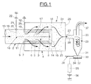
- an electrostatic filtering cell referenced 1 as a whole, comprises an intake duct 2, a collector 4, and a filtering unit 3 between the pipe intake 2 and the collector 4.
- the filter unit 3 comprises an external electrode 5 of generally cylindrical shape.
- the electrode 5 forms an axial passage 6 that she surrounds.
- the outer electrode 5 comprises radial front surfaces referenced 7 and 8.
- the front face 7 comes into axial contact with a ring 9 for fixing the external electrode 5 on the pipe 2.
- the fixing ring 9 comprises a surface 10 in contact with a bore 11 of the intake pipe 2.
- the crown. 9 is crossed by a conductor 12 radially outgoing of the ring 9 and connected to the external electrode 5.
- the driver 12 electrically connects the external electrode 5 to a mass of zero potential.
- the external electrode 5 is open on the side of its front surface 7, so that the central passage 6 communicates with the driving 2.
- the intake pipe 2 includes an orifice 13 opposite side to the outer electrode 5.
- a disc 14 comes in axial support by a radial surface 15 against the front surface 8 of the external electrode 5 opposite to the intake pipe 2. The disc 14 axially closes the central passage 7 on the side opposite the intake pipe 2.
- the filter unit 3 also comprises an electrode central 16 in the form of a rod 17 coaxial with the external electrode 5 and whose end 18 is plugged into an insulating portion of the disc 14.
- the inner electrode 16 extends axially from its end 18 beyond the fixing ring 9 being bent to forming a radial portion 19 radially out of the pipe intake 2 through an opening 20 formed in a wall of the intake pipe 2.
- An insulator 21 is disposed in the opening 20 to electrically isolate the wall of the intake pipe 2 from the internal electrode 16.
- the radial portion 19 is electrically connected to a source of tension 22.
- the collector 4 comprises a cylindrical envelope 23 surrounding the portion of the outer electrode 5 located outside the intake duct 2.
- the cylindrical casing 23 extends axially beyond, the disc 14.
- the envelope 23 comprises a inner diameter greater than the outer diameter of the electrode external 5, so that there is an empty annular space 24 between the cylindrical envelope 23 and the external electrode 5.
- the collector 4 comprises a radial wall 25 connecting the envelope 25 located on the side of the intake pipe 2 at the end of the intake pipe 2, tightly.
- the collector 4 is closed on the opposite side to the intake pipe 2 by a radial wall 26 provided with a central opening 27, into which a delivery pipe opens 28 to a mechanical collector 29 of the cyclone type.
- the collector 29 comprises a cylindrical portion 30 extended at the bottom by a conical portion 31 comprising an opening 32, which opens into a recovery tank 33.
- the recovery tank comprises a device of the type heating cord 34 connected to an electrical control device 35 connected to a power source 36.
- the collector 29 comprises a exhaust pipe 37 treated exhaust gas opposite the recovery tank 33.
- Particle-laden exhaust gases enter the intake pipe 2 through the inlet port 13.
- the gases exhausted particles flow into the central passage 6 of the external electrode 5, which communicates with the pipe 2, in which they are ionized and the charged particles electrically.
- the disk 14 prevents the axial passage of the gases exhaust.
- the exhaust gases are deflected radially and pass through the outer electrode 5 which is permeable to gases.
- the charged particles subjected to a strong field migrate specifically towards these asperities on very short distances. Exhaust gases pass into space annular 24, then flow in the collector 4 to the collector mechanical 29 cyclone type.
- the clusters of particles, stored in the recovery tank 33 are burned by the device of the heating cord type 34 preferably arranged on the inner wall of the bottom of the recovery tank 33, the device of the heating cord type 34 is connected to a system of electrical control 35.
- the electrical control system 35 is electrically connected to a current source 36 which makes it possible to generate heating of the deposit of particle clusters and to provoke their combustion.
- the electrical control system 35 is mounted way to trigger periodically depending for example on kilometers traveled, operating time, or by through a probe measuring the amount of particle clusters stored on the heating cord. We can choose a trigger all the fifty kilometers.
- the exhaust pipe 37 of the gases Treated exhaust can be connected to an exhaust outlet directly, or through different volumes of catalysts, for example oxidation-reduction type oxides nitrogen.
- the recovery tank 33 comprises a pipe 38 of exhaust gas recirculation connected to the combustion chamber of the motor.
- This recirculation pipe 38 carries the residue of filtration in the form of concentrated gas particles in the chamber to combustion of the engine, where the particles will be burned.
- the recirculation pipe 38 joins an intake pipe in the air of the combustion chamber.
- EGR valve (not shown) allows to regulate the flow of exhaust gas towards the combustion chamber, so a larger or smaller amount of Particle clumps can be destroyed.
- the EGR strategy is the following: for low flow rates, particle clusters rejected are large and sediment easily, burning storage on a support, with a device of the heating cord type 34 is therefore preferable. For high flow rates, where particle clusters are small and difficult to remember, and where the flow of admission to the EGR is maximum, a pumping of the concentrated gas into particles is with the recirculation line 38. In the event that a Exhaust gas recirculation strategy is not envisaged, the filtering device may not include conduct of recirculation 38.
- the external electrode 5 is maintained at a zero potential, the internal electrode 16 being brought to a positive or negative potential.
- the potential difference created between the external electrode 5 and the internal electrode 16 induces the presence of an electric field in the axial passage 6. If this electric field has sufficient intensity, particularly in very close neighborhood of the internal electrode 16, there occurs a partial or total ionization of gases, or medium, between internal electrodes 16 and external 5.
- the particles present in the exhaust gases are charge mainly by collision and combination with free electrons.
- the probability that an electron moving rapidly from the internal electrode 16 to the external electrode 5 strikes a particle and combines with the latter is weak.
- the internal electrode 16 must therefore be brought to a high potential, for example between 50 and 150 kV.
- the increase of the potential at which the internal electrode 16 is carried also effect the ionization of a gaseous medium in a volume wider.
- the ionization of the entire volume between the internal and external electrodes 18 and 5 require an energy considerable.
- a positive internal electrode 16 allows ionization the volume between the internal electrode 16 and the external electrode 5 with low energy input, brought to a positive potential less, for example between 1 kV and 50 kV.
- the almost homogeneous electric field in the inter-electrode space deflects charged particles that migrate to the electrode porous.
- the electric field is heterogeneous only in the vicinity two electrodes.
- the field lines electric converge towards the fibers of the porous electrode.
- the particles are then precipitated against the fibers by the strong local electric field increases. Since the field is zero inside the porous electrode and its surface developed is weak, the majority of particles reach the electrode as soon as the first row of fibers and almost no capture in depth does not occur.
- Particles charged and deposited on the internal surface of the electrode agglomerate by interactions electrostatic and by Van der Waals forces. Particle clusters then grow to a size sufficient for friction forces exerted by the exhaust gases tear them off. The clusters of particles grow to their ejection out of the porous electrode in the form of agglomerates.
- the size ratio between the particles of exhaust gases emitted by the engine, about 100 nm, and clusters particles thus recovered, is 100 to 1000.
- the majority of Agglomerated particles then have a size greater than 5 ⁇ m.
- the device filtering comprises instead of the collector 29 cyclone type a propeller manifold 39 comprising a propeller 39a, a wall cylindrical 40, and a heating cord 41 disposed on the periphery inside the cylindrical wall 40 of the propeller manifold.
- the 39a propeller creates a vortex inside the manifold 39.
- the vortex rotates the gaseous flow which tends to ensure a centrifugation effect of particles and to press them against the cylindrical wall 40 of the collector, we then obtain a deposit of particle clusters.
- Particle clusters stored (represented schematically by triangles), are then burns via heating cord 41.
- Driving discharge 37 discharges the exhaust gas treated.
- the filtering device comprises in a manner analogous to the previous embodiment, a gas recirculation line 38 exhaust that can be removed or not depending on the chosen strategy for the removal of the deposition of the particles.
- the filtering device comprises an electric separator 42 comprising an electrode 43 may be of wired type.
- the electrode 43 extends axially by being bent at each of its ends to form two radial portions 44 and 45 coming out of the electrical separator 42 by two openings 46 and 47.
- Two insulators 48 and 49 are arranged in the openings 46 and 47 to electrically isolate the wall of the electrical separator 42 of the electrode 43.
- the radial portions 44 and 45 are electrically connected to a voltage source 50.
- the voltage source 22 of the filter cell 1 can be used.
- the electrical separator 42 comprises a cord heater 52 and perforated discs 51, extending radially and spaced apart.
- the exhaust gases loaded with Agglomerated particles are radially deflected by the field created at inside the electric separator 42.
- the agglomerated particles thus charged are stopped by perforated discs 51.
- the particles The agglomerates are then burned using the heating cord 52.
- an injection of a very powerful oxidizing compound for example ozone O 3
- ozone O 3 can ensure the oxidation of the deposition of particles.
- hydrogen H 2 which by reaction with oxygen O 2 under certain thermodynamic conditions allows an overall increase in the temperature of the gases, to achieve the combustion of the deposit.
- a particle filter assembly 53 comprises a common inlet 55 which conveys the exhaust gas charged in particles, the elements identical to the preceding figures bearing the same references.
- the distributor 54 has a plurality outputs 56, here four in number and thus allows the flow in order to have a better efficiency of the devices of filtering.
- Each output 56 is connected to the input of a device of filtering 1 as described above.
- a general collector 57 is connected to the outputs of the electrostatic filtering devices 1.
- the set of electrostatic filtering devices 1 can be find in the same volume, two plates pierced with orifices to act as distributor and collector of gases exhaust. (The particles contained in the exhaust upstream of the filtering devices 1 and the particle clusters generated downstream of the filtering devices 1 have not been shown).
- This general collector 57 comprises a supply line 58 to a mechanical collector 29 cyclone type as described above, common to all the filtering devices. Cyclone 29 is associated with a device for eliminating particle clusters of the type heating cord 34 and a vent pipe 37. Well heard, the filtering unit 53 can be connected to the other means of recovery and elimination mentioned above.
- the device includes in a manner similar to the embodiments preceding, an exhaust gas recirculation line 38 can be removed or not according to the strategy, selected for the elimination of the deposition of the particles.
Landscapes
- Engineering & Computer Science (AREA)
- Chemical & Material Sciences (AREA)
- Combustion & Propulsion (AREA)
- Mechanical Engineering (AREA)
- General Engineering & Computer Science (AREA)
- Processes For Solid Components From Exhaust (AREA)
- Exhaust Gas After Treatment (AREA)
- Electrostatic Separation (AREA)
- Filtering Of Dispersed Particles In Gases (AREA)
- Physical Or Chemical Processes And Apparatus (AREA)
Abstract
Description
- la figure 1 est une vue en coupe d'un dispositif de filtrage des particules selon un premier mode de réalisation de l'invention;
- la figure 2 est une vue en coupe d'un dispositif de filtrage des particules selon un deuxième mode de réalisation de l'invention;
- la figure 3 est une vue en coupe d'un dispositif de filtrage des particules selon un troisième mode de réalisation de l'invention; et
- la figure 4 est une vue d'un ensemble de filtrage comprenant des dispositifs de filtrage électrostatique montés en parallèle;
Claims (10)
- Dispositif de filtrage et d'agglomération de particules contenues dans des gaz d'échappement d'un moteur à combustion de véhicule automobile caractérisé en ce qu'il comprend au moins un moyen de filtrage électrostatique (1) comprenant une électrode interne (17), une électrode externe (5) en matière poreuse, alimentées en courant électrique, capable de laisser passer les gaz d'échappement ainsi que des amas de particules agglomérés par effet électrostatique lors du passage du gaz d'échappement à travers la matière poreuse, ledit moyen de filtrage (1) étant associé à au moins un moyen de récupération (29) et à au moins un moyen d'élimination (34) des amas de particules, montés en aval du moyen de filtrage électrostatique (1).
- Dispositif selon la revendication 1, caractérisé en ce que le moyen de récupération des amas de particules comprend un collecteur centrifuge mécanique (29, 39),
- Dispositif selon la revendication 1, caractérisé en ce que le moyen de récupération des amas de particules comprend un collecteur électrostatique (42).
- Dispositif selon la revendication 1, caractérisé en ce que le moyen d'élimination des amas de particules comprend un moyen de combustion.
- Dispositif selon la revendication 4, caractérisé en ce que le moyen de combustion est activé électriquement (34, 38).
- Dispositif selon la revendication 4, caractérisé en ce que le moyen de combustion est activé par carburant.
- Dispositif selon la revendication 4, caractérisé en ce que le moyen de combustion est activé par injection d'hydrogène H2 ou d'ozone O3.
- Dispositif selon la revendication 4, caractérisé en ce que le moyen de combustion comprend une conduite de recirculation (38) des gaz d'échappement chargés de particules provenant du dispositif de filtrage, relié à la chambre de combustion du moteur.
- Ensemble de filtrage des particules de gaz d'échappement pour véhicule automobile caractérisé en ce qu'il comprend plusieurs dispositifs de filtrage et d'agglomération de particules selon l'une quelconque des revendications précédentes, montés en parallèle et associé à un moyen commun de récupération (29) et un moyen commun d'élimination (34) des amas de particules.
- Procédé de filtrage des particules de gaz d'échappement d'un véhicule automobile, dans lequel :on agglomère mécaniquement et de façon électrostatique les particules par passage à travers une électrode poreuse;on récupère les particules à l'aide d'un collecteur; eton détruit les particules récupérées par combustion, par exemple dans un volume de stockage ou par recirculation vers la chambre de combustion d'un moteur du véhicule automobile.
Applications Claiming Priority (2)
| Application Number | Priority Date | Filing Date | Title |
|---|---|---|---|
| FR0312635 | 2003-10-29 | ||
| FR0312635A FR2861803B1 (fr) | 2003-10-29 | 2003-10-29 | Dispositif et procede de filtrage de particules contenues dans des gaz d'echappement |
Publications (2)
| Publication Number | Publication Date |
|---|---|
| EP1528230A1 true EP1528230A1 (fr) | 2005-05-04 |
| EP1528230B1 EP1528230B1 (fr) | 2009-03-11 |
Family
ID=34400872
Family Applications (1)
| Application Number | Title | Priority Date | Filing Date |
|---|---|---|---|
| EP04300696A Expired - Lifetime EP1528230B1 (fr) | 2003-10-29 | 2004-10-20 | Dispositif et procédé de filtrage de particules contenues dans des gaz d'échappement |
Country Status (4)
| Country | Link |
|---|---|
| EP (1) | EP1528230B1 (fr) |
| AT (1) | ATE425349T1 (fr) |
| DE (1) | DE602004019866D1 (fr) |
| FR (1) | FR2861803B1 (fr) |
Cited By (3)
| Publication number | Priority date | Publication date | Assignee | Title |
|---|---|---|---|---|
| WO2007116131A1 (fr) * | 2006-04-11 | 2007-10-18 | Renault S.A.S | Dispositif et procede de capture et d’elimination de particules agglomerees issues d’un filtre a particules de vehicule automobile |
| EP2299073A1 (fr) * | 2009-08-31 | 2011-03-23 | NGK Insulators, Ltd. | Appareil de traitement des gaz d'échappement |
| DE102022203622B3 (de) | 2022-01-24 | 2023-04-20 | Cummins Emission Solutions Inc. | Abgasfiltrationsvorrichtung |
Families Citing this family (4)
| Publication number | Priority date | Publication date | Assignee | Title |
|---|---|---|---|---|
| FR2887922A1 (fr) * | 2005-07-01 | 2007-01-05 | Renault Sas | Ensemble d'agglomeration et de collection des particules contenues dans des gaz d'echappement d'un moteur a combustion interne de vehicule automobile pourvu d'un dispositif d'alimentation electrique haute tension |
| FR2891006A1 (fr) | 2005-09-22 | 2007-03-23 | Renault Sas | Dispositif pour le filtrage et l'elimination des particules contenues dans les gaz d'echappement ameliorant la capture des particules |
| FR2907843B1 (fr) * | 2006-10-26 | 2009-01-23 | Renault Sas | Dispositif electrique de capture de particules de suie de gaz d'echappement de moteur a combustion interne. |
| FR2915234B1 (fr) | 2007-04-18 | 2013-08-02 | Renault Sas | Systeme de filtration electrostatique pour les gaz d'echappement d'un moteur a combustion interne. |
Citations (8)
| Publication number | Priority date | Publication date | Assignee | Title |
|---|---|---|---|---|
| US4406119A (en) * | 1980-11-21 | 1983-09-27 | Nippon Soken, Inc. | Carbon-particle decontaminating system |
| DE3314170A1 (de) * | 1983-04-19 | 1984-10-25 | Robert Bosch Gmbh, 7000 Stuttgart | Verfahren und vorrichtung zum reinigen von gasen von leitfaehigen partikeln |
| DE3324886A1 (de) * | 1983-07-09 | 1985-01-17 | Robert Bosch Gmbh, 7000 Stuttgart | Vorrichtung zum reinigen von gasen |
| DE3500375A1 (de) * | 1985-01-08 | 1986-07-10 | Robert Bosch Gmbh, 7000 Stuttgart | Vorrichtung zum entfernen von festkoerperpartikeln, insbesondere russteilchen, aus dem abgas von brennkraftmaschinen |
| US5458850A (en) * | 1993-06-10 | 1995-10-17 | Daimler-Benz Aktiengesellschaft | Method and apparatus for reducing exhaust gases particles |
| US5557923A (en) * | 1992-07-15 | 1996-09-24 | Linde Aktiengesellschaft | Method and device for removing particles from exhaust gases from internal combustion engines |
| US5695549A (en) * | 1996-04-05 | 1997-12-09 | Environmental Elements Corp. | System for removing fine particulates from a gas stream |
| EP1051234A1 (fr) * | 1998-01-29 | 2000-11-15 | AEA Technology plc | Traitement de gaz a assistance plasma |
Family Cites Families (2)
| Publication number | Priority date | Publication date | Assignee | Title |
|---|---|---|---|---|
| DE3141156A1 (de) | 1981-10-16 | 1983-04-28 | Robert Bosch Gmbh, 7000 Stuttgart | Verfahren und vorrichtung zum entfernen von festen bestandteilen und aerosolen, insbesondere von russbestandteilen aus dem abgas von brennkraftmaschinen |
| US6262081B1 (en) | 1998-07-10 | 2001-07-17 | Dupont Pharmaceuticals Company | Composition for and method of treating neurological disorders |
-
2003
- 2003-10-29 FR FR0312635A patent/FR2861803B1/fr not_active Expired - Fee Related
-
2004
- 2004-10-20 AT AT04300696T patent/ATE425349T1/de not_active IP Right Cessation
- 2004-10-20 DE DE602004019866T patent/DE602004019866D1/de not_active Expired - Lifetime
- 2004-10-20 EP EP04300696A patent/EP1528230B1/fr not_active Expired - Lifetime
Patent Citations (8)
| Publication number | Priority date | Publication date | Assignee | Title |
|---|---|---|---|---|
| US4406119A (en) * | 1980-11-21 | 1983-09-27 | Nippon Soken, Inc. | Carbon-particle decontaminating system |
| DE3314170A1 (de) * | 1983-04-19 | 1984-10-25 | Robert Bosch Gmbh, 7000 Stuttgart | Verfahren und vorrichtung zum reinigen von gasen von leitfaehigen partikeln |
| DE3324886A1 (de) * | 1983-07-09 | 1985-01-17 | Robert Bosch Gmbh, 7000 Stuttgart | Vorrichtung zum reinigen von gasen |
| DE3500375A1 (de) * | 1985-01-08 | 1986-07-10 | Robert Bosch Gmbh, 7000 Stuttgart | Vorrichtung zum entfernen von festkoerperpartikeln, insbesondere russteilchen, aus dem abgas von brennkraftmaschinen |
| US5557923A (en) * | 1992-07-15 | 1996-09-24 | Linde Aktiengesellschaft | Method and device for removing particles from exhaust gases from internal combustion engines |
| US5458850A (en) * | 1993-06-10 | 1995-10-17 | Daimler-Benz Aktiengesellschaft | Method and apparatus for reducing exhaust gases particles |
| US5695549A (en) * | 1996-04-05 | 1997-12-09 | Environmental Elements Corp. | System for removing fine particulates from a gas stream |
| EP1051234A1 (fr) * | 1998-01-29 | 2000-11-15 | AEA Technology plc | Traitement de gaz a assistance plasma |
Cited By (4)
| Publication number | Priority date | Publication date | Assignee | Title |
|---|---|---|---|---|
| WO2007116131A1 (fr) * | 2006-04-11 | 2007-10-18 | Renault S.A.S | Dispositif et procede de capture et d’elimination de particules agglomerees issues d’un filtre a particules de vehicule automobile |
| EP2299073A1 (fr) * | 2009-08-31 | 2011-03-23 | NGK Insulators, Ltd. | Appareil de traitement des gaz d'échappement |
| DE102022203622B3 (de) | 2022-01-24 | 2023-04-20 | Cummins Emission Solutions Inc. | Abgasfiltrationsvorrichtung |
| DE102022203622B8 (de) | 2022-01-24 | 2023-06-15 | Cummins Emission Solutions Inc. | Abgasfiltrationsvorrichtung |
Also Published As
| Publication number | Publication date |
|---|---|
| FR2861803B1 (fr) | 2006-01-20 |
| EP1528230B1 (fr) | 2009-03-11 |
| FR2861803A1 (fr) | 2005-05-06 |
| ATE425349T1 (de) | 2009-03-15 |
| DE602004019866D1 (de) | 2009-04-23 |
Similar Documents
| Publication | Publication Date | Title |
|---|---|---|
| EP1212141B1 (fr) | Dispositif de traitment des gaz d'echappement d'un moteur a combustion interne | |
| EP1528230B1 (fr) | Dispositif et procédé de filtrage de particules contenues dans des gaz d'échappement | |
| FR2967595A1 (fr) | Dispositif de collecte de poussiere pour machine a decouper le beton | |
| EP1506347B1 (fr) | Dispositif et procede de filtrage de gaz d'echappement charges de particules | |
| FR2884857A1 (fr) | Dispositif a elements de separation par voie inertielle pour le filtrage et l'elimination de particules contenues dans des gaz d'echappement | |
| WO2008107598A1 (fr) | Dispositif de filtre electrostatique pour la capture et la destruction de particules de suie contenues dans les gaz d'echappement d'un moteur a combustion | |
| FR2861131A1 (fr) | Systeme de filtration electrostatique de particules de suie des gaz d'echappement d'un moteur a combustion interne et procede de regeneration d'un tel systeme | |
| FR2915234A1 (fr) | Systeme de filtration electrostatique pour les gaz d'echappement d'un moteur a combustion interne. | |
| FR2880062A1 (fr) | Dispositif et procede de capture et d'elimination de particules agglomerees issues d'un filtre a particules de vehicule automobile | |
| FR2543216A1 (fr) | Installation pour eliminer les composants solides des gaz d'echappement de moteurs a combustion interne | |
| WO2007116131A1 (fr) | Dispositif et procede de capture et d’elimination de particules agglomerees issues d’un filtre a particules de vehicule automobile | |
| EP2038521B1 (fr) | Dispositif et procede pour la capture et l'elimination des particules contenues dans les gaz d'echappement d'un moteur a combustion interne de vehicule automobile | |
| FR2887922A1 (fr) | Ensemble d'agglomeration et de collection des particules contenues dans des gaz d'echappement d'un moteur a combustion interne de vehicule automobile pourvu d'un dispositif d'alimentation electrique haute tension | |
| FR2864143A1 (fr) | Systeme de filtration electrostatique pour les gaz d'echappement d'un moteur a combustion interne | |
| FR2907843A1 (fr) | Dispositif electrique de capture de particules de suie de gaz d'echappement de moteur a combustion interne. | |
| FR2822893A1 (fr) | Systeme de traitement des gaz d'echappement | |
| EP4070888A1 (fr) | Dispositif électrostatique de filtrage de particules de poussières de freinage | |
| FR2880061A1 (fr) | Filtre a particules pour le traitement de gaz d'echappement issus d'un moteur a combustion interne de vehicule automobile et procede de filtrage de gaz d'echappement correspondant | |
| FR3082760A1 (fr) | Dispositif de purification d'un milieu gazeux charge de particules | |
| FR2884858A1 (fr) | Dispositif pour le filtrage et l'elimination des particules contenues dans des gaz d'echappement ameliorant la capture des particules | |
| FR2864141A1 (fr) | Systeme de filtration electrostatique pour les gaz d'echappement d'un moteur a combustion interne | |
| FR2904656A1 (fr) | Dispositif de traitement de polluants contenus dans des effluents gazeux d'un vehicule automobile et procede associe. | |
| EP2417396A1 (fr) | Dispositif perfectionné d'épuration des gaz et fumées de combustion d'un appareil de chauffage à combustible solide notamment à bois | |
| FR2891006A1 (fr) | Dispositif pour le filtrage et l'elimination des particules contenues dans les gaz d'echappement ameliorant la capture des particules | |
| FR3079264A1 (fr) | Organe de purification de gaz d'echappement chauffant et dispositif de purification comprenant un tel organe de purification |
Legal Events
| Date | Code | Title | Description |
|---|---|---|---|
| PUAI | Public reference made under article 153(3) epc to a published international application that has entered the european phase |
Free format text: ORIGINAL CODE: 0009012 |
|
| AK | Designated contracting states |
Kind code of ref document: A1 Designated state(s): AT BE BG CH CY CZ DE DK EE ES FI FR GB GR HU IE IT LI LU MC NL PL PT RO SE SI SK TR |
|
| AX | Request for extension of the european patent |
Extension state: AL HR LT LV MK |
|
| 17P | Request for examination filed |
Effective date: 20051024 |
|
| AKX | Designation fees paid |
Designated state(s): AT BE BG CH CY CZ DE DK EE ES FI FR GB GR HU IE IT LI LU MC NL PL PT RO SE SI SK TR |
|
| 17Q | First examination report despatched |
Effective date: 20070816 |
|
| GRAP | Despatch of communication of intention to grant a patent |
Free format text: ORIGINAL CODE: EPIDOSNIGR1 |
|
| GRAS | Grant fee paid |
Free format text: ORIGINAL CODE: EPIDOSNIGR3 |
|
| GRAA | (expected) grant |
Free format text: ORIGINAL CODE: 0009210 |
|
| AK | Designated contracting states |
Kind code of ref document: B1 Designated state(s): AT BE BG CH CY CZ DE DK EE ES FI FR GB GR HU IE IT LI LU MC NL PL PT RO SE SI SK TR |
|
| REG | Reference to a national code |
Ref country code: GB Ref legal event code: FG4D Free format text: NOT ENGLISH |
|
| REG | Reference to a national code |
Ref country code: CH Ref legal event code: EP |
|
| REG | Reference to a national code |
Ref country code: IE Ref legal event code: FG4D Free format text: LANGUAGE OF EP DOCUMENT: FRENCH |
|
| REF | Corresponds to: |
Ref document number: 602004019866 Country of ref document: DE Date of ref document: 20090423 Kind code of ref document: P |
|
| PG25 | Lapsed in a contracting state [announced via postgrant information from national office to epo] |
Ref country code: SI Free format text: LAPSE BECAUSE OF FAILURE TO SUBMIT A TRANSLATION OF THE DESCRIPTION OR TO PAY THE FEE WITHIN THE PRESCRIBED TIME-LIMIT Effective date: 20090311 Ref country code: FI Free format text: LAPSE BECAUSE OF FAILURE TO SUBMIT A TRANSLATION OF THE DESCRIPTION OR TO PAY THE FEE WITHIN THE PRESCRIBED TIME-LIMIT Effective date: 20090311 Ref country code: NL Free format text: LAPSE BECAUSE OF FAILURE TO SUBMIT A TRANSLATION OF THE DESCRIPTION OR TO PAY THE FEE WITHIN THE PRESCRIBED TIME-LIMIT Effective date: 20090311 |
|
| NLV1 | Nl: lapsed or annulled due to failure to fulfill the requirements of art. 29p and 29m of the patents act | ||
| PG25 | Lapsed in a contracting state [announced via postgrant information from national office to epo] |
Ref country code: AT Free format text: LAPSE BECAUSE OF FAILURE TO SUBMIT A TRANSLATION OF THE DESCRIPTION OR TO PAY THE FEE WITHIN THE PRESCRIBED TIME-LIMIT Effective date: 20090311 Ref country code: PL Free format text: LAPSE BECAUSE OF FAILURE TO SUBMIT A TRANSLATION OF THE DESCRIPTION OR TO PAY THE FEE WITHIN THE PRESCRIBED TIME-LIMIT Effective date: 20090311 Ref country code: SE Free format text: LAPSE BECAUSE OF FAILURE TO SUBMIT A TRANSLATION OF THE DESCRIPTION OR TO PAY THE FEE WITHIN THE PRESCRIBED TIME-LIMIT Effective date: 20090611 |
|
| REG | Reference to a national code |
Ref country code: IE Ref legal event code: FD4D |
|
| PG25 | Lapsed in a contracting state [announced via postgrant information from national office to epo] |
Ref country code: CZ Free format text: LAPSE BECAUSE OF FAILURE TO SUBMIT A TRANSLATION OF THE DESCRIPTION OR TO PAY THE FEE WITHIN THE PRESCRIBED TIME-LIMIT Effective date: 20090311 Ref country code: IE Free format text: LAPSE BECAUSE OF FAILURE TO SUBMIT A TRANSLATION OF THE DESCRIPTION OR TO PAY THE FEE WITHIN THE PRESCRIBED TIME-LIMIT Effective date: 20090311 Ref country code: PT Free format text: LAPSE BECAUSE OF FAILURE TO SUBMIT A TRANSLATION OF THE DESCRIPTION OR TO PAY THE FEE WITHIN THE PRESCRIBED TIME-LIMIT Effective date: 20090824 Ref country code: ES Free format text: LAPSE BECAUSE OF FAILURE TO SUBMIT A TRANSLATION OF THE DESCRIPTION OR TO PAY THE FEE WITHIN THE PRESCRIBED TIME-LIMIT Effective date: 20090622 Ref country code: EE Free format text: LAPSE BECAUSE OF FAILURE TO SUBMIT A TRANSLATION OF THE DESCRIPTION OR TO PAY THE FEE WITHIN THE PRESCRIBED TIME-LIMIT Effective date: 20090311 |
|
| PG25 | Lapsed in a contracting state [announced via postgrant information from national office to epo] |
Ref country code: RO Free format text: LAPSE BECAUSE OF FAILURE TO SUBMIT A TRANSLATION OF THE DESCRIPTION OR TO PAY THE FEE WITHIN THE PRESCRIBED TIME-LIMIT Effective date: 20090311 Ref country code: SK Free format text: LAPSE BECAUSE OF FAILURE TO SUBMIT A TRANSLATION OF THE DESCRIPTION OR TO PAY THE FEE WITHIN THE PRESCRIBED TIME-LIMIT Effective date: 20090311 |
|
| PLBE | No opposition filed within time limit |
Free format text: ORIGINAL CODE: 0009261 |
|
| STAA | Information on the status of an ep patent application or granted ep patent |
Free format text: STATUS: NO OPPOSITION FILED WITHIN TIME LIMIT |
|
| PG25 | Lapsed in a contracting state [announced via postgrant information from national office to epo] |
Ref country code: DK Free format text: LAPSE BECAUSE OF FAILURE TO SUBMIT A TRANSLATION OF THE DESCRIPTION OR TO PAY THE FEE WITHIN THE PRESCRIBED TIME-LIMIT Effective date: 20090311 Ref country code: BG Free format text: LAPSE BECAUSE OF FAILURE TO SUBMIT A TRANSLATION OF THE DESCRIPTION OR TO PAY THE FEE WITHIN THE PRESCRIBED TIME-LIMIT Effective date: 20090611 |
|
| 26N | No opposition filed |
Effective date: 20091214 |
|
| BERE | Be: lapsed |
Owner name: RENAULT S.A.S. Effective date: 20091031 |
|
| PG25 | Lapsed in a contracting state [announced via postgrant information from national office to epo] |
Ref country code: MC Free format text: LAPSE BECAUSE OF NON-PAYMENT OF DUE FEES Effective date: 20091031 |
|
| REG | Reference to a national code |
Ref country code: CH Ref legal event code: PL |
|
| REG | Reference to a national code |
Ref country code: FR Ref legal event code: ST Effective date: 20100630 |
|
| PG25 | Lapsed in a contracting state [announced via postgrant information from national office to epo] |
Ref country code: FR Free format text: LAPSE BECAUSE OF NON-PAYMENT OF DUE FEES Effective date: 20091102 |
|
| PG25 | Lapsed in a contracting state [announced via postgrant information from national office to epo] |
Ref country code: BE Free format text: LAPSE BECAUSE OF NON-PAYMENT OF DUE FEES Effective date: 20091031 Ref country code: GR Free format text: LAPSE BECAUSE OF FAILURE TO SUBMIT A TRANSLATION OF THE DESCRIPTION OR TO PAY THE FEE WITHIN THE PRESCRIBED TIME-LIMIT Effective date: 20090612 Ref country code: LI Free format text: LAPSE BECAUSE OF NON-PAYMENT OF DUE FEES Effective date: 20091031 Ref country code: CH Free format text: LAPSE BECAUSE OF NON-PAYMENT OF DUE FEES Effective date: 20091031 |
|
| PG25 | Lapsed in a contracting state [announced via postgrant information from national office to epo] |
Ref country code: IT Free format text: LAPSE BECAUSE OF FAILURE TO SUBMIT A TRANSLATION OF THE DESCRIPTION OR TO PAY THE FEE WITHIN THE PRESCRIBED TIME-LIMIT Effective date: 20090311 |
|
| PG25 | Lapsed in a contracting state [announced via postgrant information from national office to epo] |
Ref country code: LU Free format text: LAPSE BECAUSE OF NON-PAYMENT OF DUE FEES Effective date: 20091020 |
|
| PG25 | Lapsed in a contracting state [announced via postgrant information from national office to epo] |
Ref country code: HU Free format text: LAPSE BECAUSE OF FAILURE TO SUBMIT A TRANSLATION OF THE DESCRIPTION OR TO PAY THE FEE WITHIN THE PRESCRIBED TIME-LIMIT Effective date: 20090912 |
|
| PG25 | Lapsed in a contracting state [announced via postgrant information from national office to epo] |
Ref country code: TR Free format text: LAPSE BECAUSE OF FAILURE TO SUBMIT A TRANSLATION OF THE DESCRIPTION OR TO PAY THE FEE WITHIN THE PRESCRIBED TIME-LIMIT Effective date: 20090311 |
|
| PG25 | Lapsed in a contracting state [announced via postgrant information from national office to epo] |
Ref country code: CY Free format text: LAPSE BECAUSE OF FAILURE TO SUBMIT A TRANSLATION OF THE DESCRIPTION OR TO PAY THE FEE WITHIN THE PRESCRIBED TIME-LIMIT Effective date: 20090311 |
|
| PGFP | Annual fee paid to national office [announced via postgrant information from national office to epo] |
Ref country code: DE Payment date: 20211020 Year of fee payment: 18 Ref country code: GB Payment date: 20211022 Year of fee payment: 18 |
|
| REG | Reference to a national code |
Ref country code: DE Ref legal event code: R119 Ref document number: 602004019866 Country of ref document: DE |
|
| GBPC | Gb: european patent ceased through non-payment of renewal fee |
Effective date: 20221020 |
|
| PG25 | Lapsed in a contracting state [announced via postgrant information from national office to epo] |
Ref country code: DE Free format text: LAPSE BECAUSE OF NON-PAYMENT OF DUE FEES Effective date: 20230503 |
|
| PG25 | Lapsed in a contracting state [announced via postgrant information from national office to epo] |
Ref country code: GB Free format text: LAPSE BECAUSE OF NON-PAYMENT OF DUE FEES Effective date: 20221020 |