EP1528153A2 - Two part kerb - Google Patents
Two part kerb Download PDFInfo
- Publication number
- EP1528153A2 EP1528153A2 EP04256684A EP04256684A EP1528153A2 EP 1528153 A2 EP1528153 A2 EP 1528153A2 EP 04256684 A EP04256684 A EP 04256684A EP 04256684 A EP04256684 A EP 04256684A EP 1528153 A2 EP1528153 A2 EP 1528153A2
- Authority
- EP
- European Patent Office
- Prior art keywords
- base member
- base
- kerb
- road surface
- unit
- Prior art date
- Legal status (The legal status is an assumption and is not a legal conclusion. Google has not performed a legal analysis and makes no representation as to the accuracy of the status listed.)
- Granted
Links
Images


Classifications
-
- E—FIXED CONSTRUCTIONS
- E01—CONSTRUCTION OF ROADS, RAILWAYS, OR BRIDGES
- E01C—CONSTRUCTION OF, OR SURFACES FOR, ROADS, SPORTS GROUNDS, OR THE LIKE; MACHINES OR AUXILIARY TOOLS FOR CONSTRUCTION OR REPAIR
- E01C11/00—Details of pavings
- E01C11/22—Gutters; Kerbs ; Surface drainage of streets, roads or like traffic areas
- E01C11/221—Kerbs or like edging members, e.g. flush kerbs, shoulder retaining means ; Joint members, connecting or load-transfer means specially for kerbs
- E01C11/222—Raised kerbs, e.g. for sidewalks ; Integrated or portable means for facilitating ascent or descent
Definitions
- the present invention relates to an apparatus and method for laying a kerb at an edge of a road surface, and relates particularly, but not exclusively, to an apparatus and method for laying a temporary kerb for use during construction work.
- Preferred embodiments of the present invention seek to overcome the above disadvantages of the prior art.
- an assembly for forming a kerb at an edge of a road surface comprising:-
- a base kerb and base course of tarmac can be laid whilst site construction work is ongoing.
- the base kerb can be made of a material which is resistant to damage due to heavy site machinery, such that when the construction work is completed the cover member can be mounted on the base member to form the completed kerb.
- the top layer of tarmac can then be laid to complete the road.
- the assembly further comprises at least one intermediate member adapted to be mounted on at least one said base, and comprising a respective third engaging portion for engaging a respective said first engaging portion.
- this provides the advantage that the intermediate member can be mounted on top of the base member such that it is level with the tarmac surface of the road. This provides the advantage that the base member is protected from site machinery passing over it, and the intermediate member which is designed to be removed once the construction work has been completed takes any damage which may be caused. The intermediate member can then be removed once site construction has been completed allowing the cover member to be positioned on top of the base member to complete the kerb.
- an upper surface of the or each said intermediate member is adapted to be positioned at substantially the same vertical level as the level of said road surface in use.
- This provides the advantage of providing a level surface for site machinery to travel across, thus presenting no edges of either the tarmac road surface or intermediate member to which damage can be caused.
- the upper surface of said base member in use may be adapted to be positioned at a lower vertical level than the level of said road surface in use.
- said cover member when said cover member is mounted to said base member, said cover member is adapted to project above the vertical level of said road surface.
- At least one said base member, intermediate member and/or cover member may be formed from durable plastics material.
- said durable plastics material may be recycled.
- said plastics material is recycled by a co-mingling process.
- This provides the advantage of reducing costs as unsorted, mixed and contaminated plastics waste can be used as raw materials for the recycling process.
- a method of forming a kerb comprising:-
- the method further comprises:-
- the step of laying at least one said base member includes laying at least one said base member such that an upper surface of said base member in use is positioned at a lower vertical level than the level of a road surface in use.
- the step of mounting at least one said intermediate member to at least one said base member may include mounting the intermediate member such that an upper surface of said intermediate member in use is positioned at substantially the same vertical level as a road surface in use.
- the step of mounting at least one said cover member to said base member includes mounting the or each said cover member such that the or each said cover member projects above the vertical level of said road surface in use.
- a road comprises a base layer of tarmac 2 covered by a top layer of tarmac 4.
- a two part kerb assembly shown generally by 6 comprises a base unit 8 and a top unit 10.
- the kerb assembly 6 is laid between concrete haunching 12 which may form part of a pathway (not shown), and a road formed from tarmac layers 2 and 4.
- the components of the three part kerb assembly comprise a base unit 8, a top unit 10 and an intermediate protective strip 14.
- Base unit 8 comprises a connection channel 8a and a connection rib 8b.
- Both the top unit 10 and protective strip 14 comprise corresponding connection channels 10a, 14a and connection ribs 10b, 14b which are formed such that both the top unit 10 and protective strip 14 can be mounted to the base unit 8.
- the connection channel 14a and connection rib 14b of protective strip 14 are adapted to resiliently engage the connection channel 8a and connection rib 8b of the base unit 8 such that the protective strip 14 can be easily removed from base unit 8.
- the base unit 8, top unit 10 and intermediate strip 14 are all formed from a post consumer recycled durable plastics material.
- the plastic material used to formed the components of the kerb assembly is produced in a co-mingling process.
- a co-mingling process allows unsorted and unwashed plastic waste products to be used as raw materials for the recycling process thus making the use of this material economically viable.
- the co-mingled plastic is surprisingly durable enough to be used to form kerb structures for roads and the like. This plastic also has the advantage that it is a lot lighter than prior art concrete kerb assemblies and therefore presents fewer problems relating to the manual handling of the kerb structures.
- the first step in the construction of a road on a new housing site using the three part kerb assembly is the laying of a plurality of base units 8 to define the edges of a road (not shown).
- the base units 8 can be levelled such that when the top units 10 are mounted onto the base units the kerb is complete and does not need re-levelling.
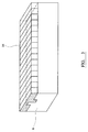
- the second step is to mount a protective strip 14 on each base unit 8.
- the connection channel 14a and rib 14b of the protective strips 14 are dimensioned such that they resiliently engage the protection channel 8a and rib 8b of each base unit 8 to allow the protection strip 14 to be removed when required.
- a base layer of tarmac can then be laid on the road surface between the base units 8.
- concrete haunching 12 can be placed alongside the base unit 8 to provide support.
- the base units 8 of the kerb assembly are protected by protective strips 14 such that plant machinery moving around the construction site can move across the kerb assembly without damaging the base unit 8 and only damaging the removable protection strips 14.
- the protection strips 14 can be removed from the base units 8 by simply pulling them off.
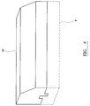
- the base units were levelled in the first step of road construction, it is not necessary to perform a further levelling operation and a plurality of top units 10 can be mounted onto the base unit 8 to complete the kerb. A top layer of finishing tarmac can then be added to the road surface to complete the road.
- FIG. 5 A second embodiment of the three part kerb assembly is shown in Figures 5 and 6.
- the base unit 16 protective strip 18 and top unit 20 are interconnected by means of a plurality of pegs 22 which are received in respective holes in the assembly members.
- the protective strip 18 protects a roadside edge of the base member 16.
- a traditional method of laying a temporary kerb has been to lay bricks in the region where the kerb is to be laid whilst construction work is performed, and then remove the bricks and replace them with kerb stone to complete the kerb. It has been found that this operation generally costs more per metre when all materials and labour costs are taken into account than the method of the present invention. If a co-mingled recycled plastic is used to form the components of the three part kerb assembly then the cost of using this method to form the kerbs is substantially less.
- the components of the three part assembly may be made from materials other that a co-mingled recycled plastic, for example reinforced concrete. It will also be appreciated that the assembly may be a two part assembly with only the top unit and base unit used and also it will be appreciated that there are other methods for interconnecting the components such as the use of adhesives etc.
Landscapes
- Engineering & Computer Science (AREA)
- Architecture (AREA)
- Civil Engineering (AREA)
- Structural Engineering (AREA)
- Road Paving Structures (AREA)
- Floor Finish (AREA)
Abstract


Description
- The present invention relates to an apparatus and method for laying a kerb at an edge of a road surface, and relates particularly, but not exclusively, to an apparatus and method for laying a temporary kerb for use during construction work.
- During the construction of new housing sites, concrete road kerbs are prone to chipping and cracking when heavy plant machinery moves over the kerb stones. As a result, kerb stones may have to be replaced once construction work has been completed on the housing site, thus increasing costs.
- Traditional concrete kerb stones are also very heavy. Current safety guidelines advise that a compact load of 30kg can be safely carried by an average male worker providing proper techniques are used, whereas an average concrete kerbstone weighs approximately 70kg. Consequently, replacing damaged kerbstones after construction work introduces manual-handling problems.
- Preferred embodiments of the present invention seek to overcome the above disadvantages of the prior art.
- According to the present invention, there is provided an assembly for forming a kerb at an edge of a road surface, the assembly comprising:-
- at least one base member adapted to be laid at an edge of said road surface, the or each said base member comprising a respective first engaging portion;
- at least one cover member adapted to be mounted on at least one said base member and comprising a respective second engaging portion for engaging a respective said first engaging portion.
-
- By providing a base member adapted to be laid at an edge of a road surface and having a first engaging portion and a cover member having a respective second engaging portion adapted to engage the first engaging portion such that the cover member can be laid on top of the base member, this means that a base kerb and base course of tarmac can be laid whilst site construction work is ongoing. The base kerb can be made of a material which is resistant to damage due to heavy site machinery, such that when the construction work is completed the cover member can be mounted on the base member to form the completed kerb. The top layer of tarmac can then be laid to complete the road. This provides two main advantages. Firstly, overall costs are reduced as there is no need to replace damaged concrete kerb stones, the cover member only needs to be put in place once the construction work is completed and heavy machinery has left the site. Also, the base unit and cover member are lighter than a complete kerb stone thus reducing the problems associated with manual handling of heavy loads.
- In a preferred embodiment, the assembly further comprises at least one intermediate member adapted to be mounted on at least one said base, and comprising a respective third engaging portion for engaging a respective said first engaging portion.
- By providing an intermediate member with a third engaging portion adapted to engage the first engaging portion of the base member, this provides the advantage that the intermediate member can be mounted on top of the base member such that it is level with the tarmac surface of the road. This provides the advantage that the base member is protected from site machinery passing over it, and the intermediate member which is designed to be removed once the construction work has been completed takes any damage which may be caused. The intermediate member can then be removed once site construction has been completed allowing the cover member to be positioned on top of the base member to complete the kerb.
- In a preferred embodiment, when at least one said intermediate member is mounted to said base member, an upper surface of the or each said intermediate member is adapted to be positioned at substantially the same vertical level as the level of said road surface in use.
- This provides the advantage of providing a level surface for site machinery to travel across, thus presenting no edges of either the tarmac road surface or intermediate member to which damage can be caused.
- The upper surface of said base member in use may be adapted to be positioned at a lower vertical level than the level of said road surface in use.
- In a preferred embodiment, when said cover member is mounted to said base member, said cover member is adapted to project above the vertical level of said road surface.
- At least one said base member, intermediate member and/or cover member may be formed from durable plastics material.
- This provides the advantage of both reducing the cost and weight of the components of the assembly.
- In a preferred embodiment, said durable plastics material may be recycled.
- In a preferred embodiment, said plastics material is recycled by a co-mingling process.
- This provides the advantage of reducing costs as unsorted, mixed and contaminated plastics waste can be used as raw materials for the recycling process.
- According to another aspect of the present invention, there is provided a method of forming a kerb, comprising:-
- laying at least one base member at an edge of a road surface; and
- mounting at least one cover member on top of at least one said base member in use, such that said cover member resiliently engages said base member.
-
- In a preferred embodiment, the method further comprises:-
- mounting at least one intermediate member on top of at least one said base member such that said intermediate member resiliently engages said base member; and
- removing the or each intermediate from the corresponding said base member.
-
- The step of laying at least one said base member includes laying at least one said base member such that an upper surface of said base member in use is positioned at a lower vertical level than the level of a road surface in use.
- The step of mounting at least one said intermediate member to at least one said base member may include mounting the intermediate member such that an upper surface of said intermediate member in use is positioned at substantially the same vertical level as a road surface in use.
- The step of mounting at least one said cover member to said base member includes mounting the or each said cover member such that the or each said cover member projects above the vertical level of said road surface in use.
- A preferred embodiment of the invention will now be described, by way of example only and not in any limitative sense, with reference to the accompanying drawings in which:-
- Figure 1 is a cross sectional view of a road incorporating a two part kerb assembly;
- Figure 2a is a cross sectional view of the top unit of the present invention;
- Figure 2b is a cross sectional view of the base unit of the present invention;
- Figure 2c is a cross sectional view of the protective strip of the present invention;
- Figure 3 is a schematic view of the base kerb unit with the protective strip of the present invention mounted thereto;
- Figure 4 is a schematic view of the base kerb unit with the upper kerb unit of the present invention mounted thereto;
- Figure 5 is a schematic view of a second embodiment of the present invention showing the base kerb unit with a protective strip mounted thereto; and
- Figure 6 is a schematic view of the second embodiment of the present invention with the upper kerb unit mounted to the base kerb unit.
-
- Referring to Figure 1, a road comprises a base layer of
tarmac 2 covered by a top layer oftarmac 4. A two part kerb assembly shown generally by 6 comprises abase unit 8 and atop unit 10. Thekerb assembly 6 is laid between concrete haunching 12 which may form part of a pathway (not shown), and a road formed fromtarmac layers - Referring to Figure 2a to 2c, the components of the three part kerb assembly comprise a
base unit 8, atop unit 10 and an intermediateprotective strip 14.Base unit 8 comprises aconnection channel 8a and aconnection rib 8b. Both thetop unit 10 andprotective strip 14 comprisecorresponding connection channels connection ribs top unit 10 andprotective strip 14 can be mounted to thebase unit 8. Preferably, theconnection channel 14a andconnection rib 14b ofprotective strip 14 are adapted to resiliently engage theconnection channel 8a andconnection rib 8b of thebase unit 8 such that theprotective strip 14 can be easily removed frombase unit 8. - The
base unit 8,top unit 10 andintermediate strip 14 are all formed from a post consumer recycled durable plastics material. The plastic material used to formed the components of the kerb assembly is produced in a co-mingling process. A co-mingling process allows unsorted and unwashed plastic waste products to be used as raw materials for the recycling process thus making the use of this material economically viable. The co-mingled plastic is surprisingly durable enough to be used to form kerb structures for roads and the like. This plastic also has the advantage that it is a lot lighter than prior art concrete kerb assemblies and therefore presents fewer problems relating to the manual handling of the kerb structures. - Referring to Figure 1 to 4, the process of building a road and kerb using the three part kerb assembly will now be described.
- The first step in the construction of a road on a new housing site using the three part kerb assembly is the laying of a plurality of
base units 8 to define the edges of a road (not shown). Thebase units 8 can be levelled such that when thetop units 10 are mounted onto the base units the kerb is complete and does not need re-levelling. The second step is to mount aprotective strip 14 on eachbase unit 8. Theconnection channel 14a andrib 14b of theprotective strips 14 are dimensioned such that they resiliently engage theprotection channel 8a andrib 8b of eachbase unit 8 to allow theprotection strip 14 to be removed when required. A base layer of tarmac can then be laid on the road surface between thebase units 8. Additionally,concrete haunching 12 can be placed alongside thebase unit 8 to provide support. In this configuration (best shown in Figure 3) thebase units 8 of the kerb assembly are protected byprotective strips 14 such that plant machinery moving around the construction site can move across the kerb assembly without damaging thebase unit 8 and only damaging the removable protection strips 14. - When the construction work is complete and it is necessary to complete construction of the road, the protection strips 14 can be removed from the
base units 8 by simply pulling them off. As the base units were levelled in the first step of road construction, it is not necessary to perform a further levelling operation and a plurality oftop units 10 can be mounted onto thebase unit 8 to complete the kerb. A top layer of finishing tarmac can then be added to the road surface to complete the road. - A second embodiment of the three part kerb assembly is shown in Figures 5 and 6. Instead of having connection channels and ribs, the
base unit 16protective strip 18 andtop unit 20 are interconnected by means of a plurality ofpegs 22 which are received in respective holes in the assembly members. In this embodiment, theprotective strip 18 protects a roadside edge of thebase member 16. - A traditional method of laying a temporary kerb has been to lay bricks in the region where the kerb is to be laid whilst construction work is performed, and then remove the bricks and replace them with kerb stone to complete the kerb. It has been found that this operation generally costs more per metre when all materials and labour costs are taken into account than the method of the present invention. If a co-mingled recycled plastic is used to form the components of the three part kerb assembly then the cost of using this method to form the kerbs is substantially less.
- Also, a single concrete kerb stone weights approximately 70 kilograms whilst the heaviest component of the three part kerb assembly weight only 40 kilograms. It can therefore be seen that the present invention is advantageous in terms of both cost and weight as well as providing a use for plastic waste thus diverting this waste from landfill sites and benefiting the environment.
- It will be appreciated by persons skilled in the art that the above embodiment have been described by way of example only, and not in any limitative sense, and that various alterations and modifications are possible without departure from the scope of the invention as defined by the appended claims. For example, it will be appreciated that the components of the three part assembly may be made from materials other that a co-mingled recycled plastic, for example reinforced concrete. It will also be appreciated that the assembly may be a two part assembly with only the top unit and base unit used and also it will be appreciated that there are other methods for interconnecting the components such as the use of adhesives etc.
Claims (10)
- An assembly for forming a kerb at an edge of a road surface, the assembly comprising:-at least one base member adapted to be laid at an edge of said road surface, the or each said base member comprising a respective first engaging portion;at least one cover member adapted to be mounted on at least one said base member and comprising a respective second engaging portion for engaging a respective said first engaging portion.
- An assembly according to claim 1, further comprising at least one intermediate member adapted to be mounted on at least one said base, and comprising a respective third engaging portion for engaging a respective said first engaging portion.
- An assembly according to claim 2, wherein when at least one said intermediate member is mounted to said base member, an upper surface of the or each said intermediate member is adapted to be positioned at substantially the same vertical level as the level of said road surface in use.
- An assembly according to any one of the preceding claims, wherein an upper surface of said base member in use is adapted to be positioned at a lower vertical level than the level of said road surface in use.
- An assembly according to any one of the preceding claims, wherein when said cover member is mounted to said base member, said cover member is adapted to project above the vertical level of said road surface.
- An assembly according to any one of the preceding claims, wherein at least one said base member, intermediate member and/or cover member is formed from durable plastics material.
- An assembly according to claim 6, wherein said durable plastics material is recycled.
- An assembly according to claim 7, wherein said plastics material is recycled by a co-mingling process.
- A method of forming a kerb, comprising:-laying at least one base member at an edge of a road surface; andmounting at least one cover member on top of at least one said base member in use, such that said cover member resiliently engages said base member.
- A method according to claim 9, further comprising one or more of the following steps:-a) mounting at least one intermediate member on top of at least one said base member such that said intermediate member resiliently engages said base member; and
removing the or each intermediate member from the corresponding said base member;b) wherein the step of laying at least one said base member includes laying at least one said base member such that an upper surface of said base member in use is positioned at a lower vertical level than the level of a road surface in use;c) wherein the step of mounting at least one said intermediate member to at least one said base member includes mounting the intermediate member such that an upper surface of said intermediate member in use is positioned at substantially the same vertical level as a road surface in use; andd) wherein the step of mounting at least one said cover member to said base member includes mounting the or each said cover member such that the or each said cover member projects above the vertical level of said road surface in use.
Applications Claiming Priority (4)
| Application Number | Priority Date | Filing Date | Title |
|---|---|---|---|
| GB0325185 | 2003-10-28 | ||
| GBGB0325185.7A GB0325185D0 (en) | 2003-10-28 | 2003-10-28 | Key-kerb |
| GB0405725 | 2004-03-15 | ||
| GB0405725A GB2407606B (en) | 2003-10-28 | 2004-03-15 | Apparatus and method for laying a kerb |
Publications (3)
| Publication Number | Publication Date |
|---|---|
| EP1528153A2 true EP1528153A2 (en) | 2005-05-04 |
| EP1528153A3 EP1528153A3 (en) | 2006-01-04 |
| EP1528153B1 EP1528153B1 (en) | 2009-07-08 |
Family
ID=34424895
Family Applications (1)
| Application Number | Title | Priority Date | Filing Date |
|---|---|---|---|
| EP20040256684 Active EP1528153B1 (en) | 2003-10-28 | 2004-10-28 | Two part kerb |
Country Status (1)
| Country | Link |
|---|---|
| EP (1) | EP1528153B1 (en) |
Cited By (1)
| Publication number | Priority date | Publication date | Assignee | Title |
|---|---|---|---|---|
| GB2587004A (en) * | 2019-09-12 | 2021-03-17 | Geo Bloc Ltd | An edge restraint |
Citations (2)
| Publication number | Priority date | Publication date | Assignee | Title |
|---|---|---|---|---|
| WO1992009747A1 (en) | 1990-12-03 | 1992-06-11 | Trevor George Smith | Kerbing structure |
| WO2002004748A1 (en) | 2000-07-07 | 2002-01-17 | Everest Industries Limited | Kerb |
Family Cites Families (2)
| Publication number | Priority date | Publication date | Assignee | Title |
|---|---|---|---|---|
| GB683336A (en) * | 1950-09-21 | 1952-11-26 | Martin Harry Jones | Unit kerbs |
| GB2280464B (en) * | 1993-07-29 | 1996-11-27 | Joan Otterson | Kerb sytem |
-
2004
- 2004-10-28 EP EP20040256684 patent/EP1528153B1/en active Active
Patent Citations (2)
| Publication number | Priority date | Publication date | Assignee | Title |
|---|---|---|---|---|
| WO1992009747A1 (en) | 1990-12-03 | 1992-06-11 | Trevor George Smith | Kerbing structure |
| WO2002004748A1 (en) | 2000-07-07 | 2002-01-17 | Everest Industries Limited | Kerb |
Cited By (2)
| Publication number | Priority date | Publication date | Assignee | Title |
|---|---|---|---|---|
| GB2587004A (en) * | 2019-09-12 | 2021-03-17 | Geo Bloc Ltd | An edge restraint |
| GB2587004B (en) * | 2019-09-12 | 2022-04-20 | Geo Bloc Ltd | An edge restraint |
Also Published As
| Publication number | Publication date |
|---|---|
| EP1528153A3 (en) | 2006-01-04 |
| EP1528153B1 (en) | 2009-07-08 |
Similar Documents
| Publication | Publication Date | Title |
|---|---|---|
| US8662787B2 (en) | Structural underlayment support system for use with paving and flooring elements | |
| US6695527B2 (en) | Interlocking mat system for construction of load supporting surfaces | |
| CA2833401C (en) | Improved heavy duty modular flooring and roadway device | |
| CA2647547C (en) | A temporary road element | |
| US5273373A (en) | Method for road construction | |
| US5163776A (en) | Method for road construction | |
| US4889444A (en) | Method and apparatus for construction of artificial roads | |
| CN103866670B (en) | Fabricated vehicle bearing pavement and construction method thereof | |
| US20070119002A1 (en) | Protection system for surfaces of infrastructure improvements in a construction environment | |
| KR100773122B1 (en) | Manhole repair method | |
| US20080104925A1 (en) | Concrete paved area | |
| WO2002010514A1 (en) | Synthetic kerbs and method of use | |
| CA1218551A (en) | Prefabricated pavement module | |
| Pulaski et al. | Field guide for sustainable construction | |
| US20040067336A1 (en) | Curb mat | |
| CN101392497B (en) | Wellhead maintenance method and device thereof | |
| EP1528153A2 (en) | Two part kerb | |
| GB2407606A (en) | Assembly for forming a kerb | |
| JP2006022574A (en) | Road repairing method and temporary material for road | |
| GB2490722A (en) | Edging product for raised platforms incorporating a tactile surface | |
| CN205918017U (en) | With prefabricated staircase of guardrail integration, prefabricated air conditioner board | |
| JP2003247202A (en) | Technique for preventing peeling of pavement around structure such as manhole cover supporting frame | |
| US10434549B1 (en) | Temporary transfer stations | |
| JP4437734B2 (en) | Bridge tread or control board tread and method of manufacturing the same | |
| WO2000079054A1 (en) | Highway repair |
Legal Events
| Date | Code | Title | Description |
|---|---|---|---|
| PUAI | Public reference made under article 153(3) epc to a published international application that has entered the european phase |
Free format text: ORIGINAL CODE: 0009012 |
|
| AK | Designated contracting states |
Kind code of ref document: A2 Designated state(s): AT BE BG CH CY CZ DE DK EE ES FI FR GB GR HU IE IT LI LU MC NL PL PT RO SE SI SK TR |
|
| AX | Request for extension of the european patent |
Extension state: AL HR LT LV MK |
|
| PUAL | Search report despatched |
Free format text: ORIGINAL CODE: 0009013 |
|
| 17P | Request for examination filed |
Effective date: 20051102 |
|
| AK | Designated contracting states |
Kind code of ref document: A3 Designated state(s): AT BE BG CH CY CZ DE DK EE ES FI FR GB GR HU IE IT LI LU MC NL PL PT RO SE SI SK TR |
|
| AX | Request for extension of the european patent |
Extension state: AL HR LT LV MK |
|
| AKX | Designation fees paid |
Designated state(s): AT BE BG CH CY CZ DE DK EE ES FI FR GB GR HU IE IT LI LU MC NL PL PT RO SE SI SK TR |
|
| 17Q | First examination report despatched |
Effective date: 20080131 |
|
| GRAP | Despatch of communication of intention to grant a patent |
Free format text: ORIGINAL CODE: EPIDOSNIGR1 |
|
| GRAS | Grant fee paid |
Free format text: ORIGINAL CODE: EPIDOSNIGR3 |
|
| GRAA | (expected) grant |
Free format text: ORIGINAL CODE: 0009210 |
|
| AK | Designated contracting states |
Kind code of ref document: B1 Designated state(s): AT BE BG CH CY CZ DE DK EE ES FI FR GB GR HU IE IT LI LU MC NL PL PT RO SE SI SK TR |
|
| REG | Reference to a national code |
Ref country code: GB Ref legal event code: FG4D |
|
| REG | Reference to a national code |
Ref country code: CH Ref legal event code: EP |
|
| REG | Reference to a national code |
Ref country code: IE Ref legal event code: FG4D |
|
| REF | Corresponds to: |
Ref document number: 602004021889 Country of ref document: DE Date of ref document: 20090820 Kind code of ref document: P |
|
| PG25 | Lapsed in a contracting state [announced via postgrant information from national office to epo] |
Ref country code: SI Free format text: LAPSE BECAUSE OF FAILURE TO SUBMIT A TRANSLATION OF THE DESCRIPTION OR TO PAY THE FEE WITHIN THE PRESCRIBED TIME-LIMIT Effective date: 20090708 |
|
| NLV1 | Nl: lapsed or annulled due to failure to fulfill the requirements of art. 29p and 29m of the patents act | ||
| PG25 | Lapsed in a contracting state [announced via postgrant information from national office to epo] |
Ref country code: FI Free format text: LAPSE BECAUSE OF FAILURE TO SUBMIT A TRANSLATION OF THE DESCRIPTION OR TO PAY THE FEE WITHIN THE PRESCRIBED TIME-LIMIT Effective date: 20090708 Ref country code: ES Free format text: LAPSE BECAUSE OF FAILURE TO SUBMIT A TRANSLATION OF THE DESCRIPTION OR TO PAY THE FEE WITHIN THE PRESCRIBED TIME-LIMIT Effective date: 20091019 Ref country code: AT Free format text: LAPSE BECAUSE OF FAILURE TO SUBMIT A TRANSLATION OF THE DESCRIPTION OR TO PAY THE FEE WITHIN THE PRESCRIBED TIME-LIMIT Effective date: 20090708 |
|
| PG25 | Lapsed in a contracting state [announced via postgrant information from national office to epo] |
Ref country code: PL Free format text: LAPSE BECAUSE OF FAILURE TO SUBMIT A TRANSLATION OF THE DESCRIPTION OR TO PAY THE FEE WITHIN THE PRESCRIBED TIME-LIMIT Effective date: 20090708 Ref country code: NL Free format text: LAPSE BECAUSE OF FAILURE TO SUBMIT A TRANSLATION OF THE DESCRIPTION OR TO PAY THE FEE WITHIN THE PRESCRIBED TIME-LIMIT Effective date: 20090708 |
|
| PG25 | Lapsed in a contracting state [announced via postgrant information from national office to epo] |
Ref country code: BG Free format text: LAPSE BECAUSE OF FAILURE TO SUBMIT A TRANSLATION OF THE DESCRIPTION OR TO PAY THE FEE WITHIN THE PRESCRIBED TIME-LIMIT Effective date: 20091008 Ref country code: PT Free format text: LAPSE BECAUSE OF FAILURE TO SUBMIT A TRANSLATION OF THE DESCRIPTION OR TO PAY THE FEE WITHIN THE PRESCRIBED TIME-LIMIT Effective date: 20091109 |
|
| PG25 | Lapsed in a contracting state [announced via postgrant information from national office to epo] |
Ref country code: EE Free format text: LAPSE BECAUSE OF FAILURE TO SUBMIT A TRANSLATION OF THE DESCRIPTION OR TO PAY THE FEE WITHIN THE PRESCRIBED TIME-LIMIT Effective date: 20090708 Ref country code: CZ Free format text: LAPSE BECAUSE OF FAILURE TO SUBMIT A TRANSLATION OF THE DESCRIPTION OR TO PAY THE FEE WITHIN THE PRESCRIBED TIME-LIMIT Effective date: 20090708 Ref country code: RO Free format text: LAPSE BECAUSE OF FAILURE TO SUBMIT A TRANSLATION OF THE DESCRIPTION OR TO PAY THE FEE WITHIN THE PRESCRIBED TIME-LIMIT Effective date: 20090708 Ref country code: DK Free format text: LAPSE BECAUSE OF FAILURE TO SUBMIT A TRANSLATION OF THE DESCRIPTION OR TO PAY THE FEE WITHIN THE PRESCRIBED TIME-LIMIT Effective date: 20090708 |
|
| PLBE | No opposition filed within time limit |
Free format text: ORIGINAL CODE: 0009261 |
|
| STAA | Information on the status of an ep patent application or granted ep patent |
Free format text: STATUS: NO OPPOSITION FILED WITHIN TIME LIMIT |
|
| PG25 | Lapsed in a contracting state [announced via postgrant information from national office to epo] |
Ref country code: MC Free format text: LAPSE BECAUSE OF NON-PAYMENT OF DUE FEES Effective date: 20091031 Ref country code: SK Free format text: LAPSE BECAUSE OF FAILURE TO SUBMIT A TRANSLATION OF THE DESCRIPTION OR TO PAY THE FEE WITHIN THE PRESCRIBED TIME-LIMIT Effective date: 20090708 Ref country code: BE Free format text: LAPSE BECAUSE OF FAILURE TO SUBMIT A TRANSLATION OF THE DESCRIPTION OR TO PAY THE FEE WITHIN THE PRESCRIBED TIME-LIMIT Effective date: 20090708 |
|
| REG | Reference to a national code |
Ref country code: CH Ref legal event code: PL |
|
| 26N | No opposition filed |
Effective date: 20100409 |
|
| PG25 | Lapsed in a contracting state [announced via postgrant information from national office to epo] |
Ref country code: CH Free format text: LAPSE BECAUSE OF NON-PAYMENT OF DUE FEES Effective date: 20091031 Ref country code: LI Free format text: LAPSE BECAUSE OF NON-PAYMENT OF DUE FEES Effective date: 20091031 Ref country code: IE Free format text: LAPSE BECAUSE OF NON-PAYMENT OF DUE FEES Effective date: 20091028 Ref country code: GR Free format text: LAPSE BECAUSE OF FAILURE TO SUBMIT A TRANSLATION OF THE DESCRIPTION OR TO PAY THE FEE WITHIN THE PRESCRIBED TIME-LIMIT Effective date: 20091009 |
|
| PG25 | Lapsed in a contracting state [announced via postgrant information from national office to epo] |
Ref country code: IT Free format text: LAPSE BECAUSE OF FAILURE TO SUBMIT A TRANSLATION OF THE DESCRIPTION OR TO PAY THE FEE WITHIN THE PRESCRIBED TIME-LIMIT Effective date: 20090708 |
|
| PG25 | Lapsed in a contracting state [announced via postgrant information from national office to epo] |
Ref country code: LU Free format text: LAPSE BECAUSE OF NON-PAYMENT OF DUE FEES Effective date: 20091028 |
|
| PG25 | Lapsed in a contracting state [announced via postgrant information from national office to epo] |
Ref country code: HU Free format text: LAPSE BECAUSE OF FAILURE TO SUBMIT A TRANSLATION OF THE DESCRIPTION OR TO PAY THE FEE WITHIN THE PRESCRIBED TIME-LIMIT Effective date: 20100109 |
|
| PG25 | Lapsed in a contracting state [announced via postgrant information from national office to epo] |
Ref country code: TR Free format text: LAPSE BECAUSE OF FAILURE TO SUBMIT A TRANSLATION OF THE DESCRIPTION OR TO PAY THE FEE WITHIN THE PRESCRIBED TIME-LIMIT Effective date: 20090708 |
|
| PG25 | Lapsed in a contracting state [announced via postgrant information from national office to epo] |
Ref country code: CY Free format text: LAPSE BECAUSE OF FAILURE TO SUBMIT A TRANSLATION OF THE DESCRIPTION OR TO PAY THE FEE WITHIN THE PRESCRIBED TIME-LIMIT Effective date: 20090708 |
|
| PG25 | Lapsed in a contracting state [announced via postgrant information from national office to epo] |
Ref country code: SE Free format text: LAPSE BECAUSE OF FAILURE TO SUBMIT A TRANSLATION OF THE DESCRIPTION OR TO PAY THE FEE WITHIN THE PRESCRIBED TIME-LIMIT Effective date: 20090708 |
|
| REG | Reference to a national code |
Ref country code: FR Ref legal event code: PLFP Year of fee payment: 12 |
|
| REG | Reference to a national code |
Ref country code: FR Ref legal event code: PLFP Year of fee payment: 13 |
|
| PGFP | Annual fee paid to national office [announced via postgrant information from national office to epo] |
Ref country code: FR Payment date: 20170330 Year of fee payment: 13 |
|
| PGFP | Annual fee paid to national office [announced via postgrant information from national office to epo] |
Ref country code: DE Payment date: 20170330 Year of fee payment: 13 |
|
| REG | Reference to a national code |
Ref country code: DE Ref legal event code: R119 Ref document number: 602004021889 Country of ref document: DE |
|
| REG | Reference to a national code |
Ref country code: FR Ref legal event code: ST Effective date: 20180629 |
|
| PG25 | Lapsed in a contracting state [announced via postgrant information from national office to epo] |
Ref country code: DE Free format text: LAPSE BECAUSE OF NON-PAYMENT OF DUE FEES Effective date: 20180501 |
|
| PG25 | Lapsed in a contracting state [announced via postgrant information from national office to epo] |
Ref country code: FR Free format text: LAPSE BECAUSE OF NON-PAYMENT OF DUE FEES Effective date: 20171031 |
|
| PGFP | Annual fee paid to national office [announced via postgrant information from national office to epo] |
Ref country code: GB Payment date: 20230920 Year of fee payment: 20 |