EP1528005A1 - Kartonbehälter und Kartonzuschnitte - Google Patents
Kartonbehälter und Kartonzuschnitte Download PDFInfo
- Publication number
- EP1528005A1 EP1528005A1 EP04024690A EP04024690A EP1528005A1 EP 1528005 A1 EP1528005 A1 EP 1528005A1 EP 04024690 A EP04024690 A EP 04024690A EP 04024690 A EP04024690 A EP 04024690A EP 1528005 A1 EP1528005 A1 EP 1528005A1
- Authority
- EP
- European Patent Office
- Prior art keywords
- panel
- pair
- sleeve
- carton
- inner sleeve
- Prior art date
- Legal status (The legal status is an assumption and is not a legal conclusion. Google has not performed a legal analysis and makes no representation as to the accuracy of the status listed.)
- Withdrawn
Links
- 239000003292 glue Substances 0.000 description 15
- 238000010276 construction Methods 0.000 description 8
- 239000000463 material Substances 0.000 description 5
- 239000011087 paperboard Substances 0.000 description 5
- 238000000034 method Methods 0.000 description 3
- 238000004806 packaging method and process Methods 0.000 description 3
- 239000002304 perfume Substances 0.000 description 3
- 125000006850 spacer group Chemical group 0.000 description 3
- 230000001154 acute effect Effects 0.000 description 2
- 230000014759 maintenance of location Effects 0.000 description 2
- 238000004026 adhesive bonding Methods 0.000 description 1
- 239000000969 carrier Substances 0.000 description 1
- 238000004519 manufacturing process Methods 0.000 description 1
- 230000035939 shock Effects 0.000 description 1
Images


Classifications
-
- B—PERFORMING OPERATIONS; TRANSPORTING
- B65—CONVEYING; PACKING; STORING; HANDLING THIN OR FILAMENTARY MATERIAL
- B65D—CONTAINERS FOR STORAGE OR TRANSPORT OF ARTICLES OR MATERIALS, e.g. BAGS, BARRELS, BOTTLES, BOXES, CANS, CARTONS, CRATES, DRUMS, JARS, TANKS, HOPPERS, FORWARDING CONTAINERS; ACCESSORIES, CLOSURES, OR FITTINGS THEREFOR; PACKAGING ELEMENTS; PACKAGES
- B65D5/00—Rigid or semi-rigid containers of polygonal cross-section, e.g. boxes, cartons or trays, formed by folding or erecting one or more blanks made of paper
- B65D5/42—Details of containers or of foldable or erectable container blanks
- B65D5/44—Integral, inserted or attached portions forming internal or external fittings
- B65D5/50—Internal supporting or protecting elements for contents
- B65D5/5002—Integral elements for containers having tubular body walls
- B65D5/5016—Integral elements for containers having tubular body walls formed by folding inwardly of extensions hinged to the side edges of the body
-
- B—PERFORMING OPERATIONS; TRANSPORTING
- B65—CONVEYING; PACKING; STORING; HANDLING THIN OR FILAMENTARY MATERIAL
- B65D—CONTAINERS FOR STORAGE OR TRANSPORT OF ARTICLES OR MATERIALS, e.g. BAGS, BARRELS, BOTTLES, BOXES, CANS, CARTONS, CRATES, DRUMS, JARS, TANKS, HOPPERS, FORWARDING CONTAINERS; ACCESSORIES, CLOSURES, OR FITTINGS THEREFOR; PACKAGING ELEMENTS; PACKAGES
- B65D5/00—Rigid or semi-rigid containers of polygonal cross-section, e.g. boxes, cartons or trays, formed by folding or erecting one or more blanks made of paper
- B65D5/42—Details of containers or of foldable or erectable container blanks
- B65D5/44—Integral, inserted or attached portions forming internal or external fittings
- B65D5/50—Internal supporting or protecting elements for contents
- B65D5/5028—Elements formed separately from the container body
- B65D5/5035—Paper elements
- B65D5/504—Racks having upstanding ridges formed by folds, and provided with slits or recesses
Definitions
- the present invention relates to a carton and a carton blank for forming said carton. More particularly, the invention relates to a carton and blank for packaging fragile articles such as bottles of perfume, for example.
- US 3,693,866 to Struble discloses a tubular carton comprising an inner and outer sections, the inner section having frangibly interconnected panels which may be separated in order to accommodate an article therebetween.
- EP699588 to CD illustrates a carton for packaging articles comprising an outer carton and a pair of inner article support structures.
- Each article support structure is hingedly connected to a side panel forming the outer carton and is secured to that side panel. Thus the article retention structures are not secured together.
- a further problem with known carriers is that the inner section and outer sleeve need to be constructed and erected at the time of loading the article. This is undesirable for modem packaging machines as it limits the machine speeds. Accordingly, the present invention seeks to overcome this problem by providing a collapsible carrier.
- the present invention seek to overcome or at least mitigate the problems of the prior art.
- a carton comprising an outer sleeve and an inner article receiving structure
- the inner article receiving structure comprises an inner sleeve having a first pair of opposed side walls secured to a first pair of opposed side walls of the outer sleeve and a second pair of opposed side walls spaced apart from a second pair of opposed side walls of the outer sleeve
- the inner structure further comprises a first transverse panel hingedly connected to one end of the inner sleeve for movement between an open position where the transverse panel allows the inner and outer sleeves to collapse into a flat form and a closed position where the transverse panel forms a first brace structure between one of the second pair side walls of the inner structure and an adjacent one of the second pair side walls of the outer sleeve and provides resistance to collapse of the inner and outer sleeves.
- the transverse panel is hingedly connected to the one second pair side wall of the inner sleeve, the transverse panel being disposed in the plane of the one second pair side wall of the inner sleeve when in the open position.
- the transverse panel is provided with a contacting panel hingedly connected to the transverse panel, and the contacting panel overlies the adjacent one second pair side wall of the outer sleeve.
- the second pair side walls of the inner sleeve have apertures for receiving and supporting portions of an article respectively.
- the apertures of the second pair side walls extend respectively into the first and second transverse panels.
- the one second pair side wall of the inner sleeve has an aperture for receiving and supporting a portion of an article.
- the aperture of the one second pair side wall extends into the transverse panel.
- the inner sleeve defines an inner sleeve axis
- outer sleeve defines an outer sleeve axis extending parallel to the inner sleeve axis
- the transverse panel is connected to the one second pair side wall of the inner sleeve along a first fold line which is generally perpendicular to the inner and outer sleeve axes.
- the inner sleeve further comprises a second transverse panel hingedly connected to the other second pair side wall of the inner sleeve for movement between an open position where the second transverse panel allows the inner and outer sleeve to collapse into a flat form and a closed position where the second transverse panel forms a second brace structure between the other second pair side wall of the inner sleeve and the other second pair side wall of the outer sleeve and provides resistance to collapse of the inner and outer sleeves.
- the outer sleeve includes an end closure structure wherein the inner sleeve comprises a bevelled portion formed in the inner sleeve such that a securing flap of the end closure structure may be guided into a gap between one of the first pair side walls.
- a carton is formed from a single blank 10 of paperboard or similar foldable sheet material adapted to accommodate an article such as a bottle, particularly a fragile article such as a bottle of perfume, for example.
- an article such as a bottle, particularly a fragile article such as a bottle of perfume, for example.
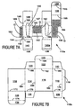
- one or more blanks could be used, one example of which is shown in Figures 7A and 7B, described in more detail below.
- the blank comprises two portions, outer sleeve 10b, and inner sleeve 10a.
- outer sleeve 10b there comprises a first side wall panel 12, first end wall panel 14, second side wall panel 16 and second end wall panel 18 are hingedly interconnected in series along fold lines 64, 66 and 68 respectively.
- a base wall panel 26 is provided that is preferably hingedly connected to first side wall panel 12 along fold line 72.
- a securing flap 34 is hingedly connected to base wall panel 20 along fold line 74.
- First and second base end flaps 28 and 30 complete a base wall structure and are preferably hingedly interconnected to first and second end wall panels 14 and 18 along fold lines 76 and 78 respectively.
- Top wall structure preferably comprises a top wall panel 22 hingedly interconnected to second side wall panel 16 along fold line 82, and top end flaps 20 and 24 hingedly connected to first and second end wall panels along fold lines 86 and 80 respectively.
- a securing flap 32 is, in this embodiment, hingedly connected to top wall panel 22 along fold line 84. It should be recognised that in alternative classes of embodiment other known top and base closure structures may be employed.
- first securing panel 62 is provided in series first securing panel 62, first article receiving structure 36, second securing panel 52, second article receiving structure 38, and third securing panel 54, hingedly interconnected along fold lines 88, 90, 92 and 94 respectively.
- First securing panel 62 is further hingedly connected to second side panel 18 of the outer sleeve 10a along fold line 70.
- Second article receiving structure 38 is, in this embodiment, essentially identical to the first article receiving structure. Therefore, only first receiving structure 36 is described in greater detail.
- Structure 36 preferably comprises central bridging panel 40, recessing panel 42, main receiving panel 44, transverse receiving panel 46 and end wall contacting panel 48 hingedly interconnected in series along fold lines 96, 98, 100 and 102 respectively.
- the comers of recessing panel 42 and main receiving panel 44 are bevelled adjacent fold line 98 for reasons explained below.
- an elongate aperture 50 is provided in main receiving panels 44 for receiving the article A, once the blank has been erected to form a carton.
- the aperture 50 extends into transverse receiving panel 46.
- the size and shape of the aperture may be altered to receive differing articles.
- An inner cover panel 56 is preferably hingedly connected to third securing panel 54 along fold line 104.
- a securing flap 58 is further advantageously hingedly connected to inner cover panel 56 along fold line 106.
- the carton of the first, second or third embodiments of the present invention can be formed by a series of sequential folding and gluing operations in a straight line machine so that the carton is not required to be rotated or inverted to complete its construction.
- the folding process is not limited to that described below and may be altered according to particular manufacturing requirements.
- the securing panels, together with article receiving structures 36 and 38 are then, in this embodiment, folded along fold lines 88, 90, 92 and 94 such that the receiving structures 36, 38 are placed in mutually opposed substantially parallel relationship, and second and third securing panels 52 and 54 are similarly placed in mutually opposed parallel relationship with the faces to which glue G has been applied facing outwardly.
- Free edge 108 of third securing panel 54 is now adjacent fold line 88, first and third securing panels 62, 54 being co-planar with the glued faces effectively now facing in the same direction.
- Outer sleeve panels 12, 14, 16 and 18 are folded out of mutual alignment so as to form an open ended tubular structure enclosing the partially erected inner sleeve 10b.
- First securing panel 62 secures the outer sleeve, and the panels of the inner sleeve are dimensioned such that second securing panel is brought into face contacting relationship with second side panel 16, and is secured thereto by glue G.
- Third side panel 54 is likewise brought into face contacting relationship with first side panel 12, and is secured thereto by glue G.
- the carton is now in the partially erected form as illustrated in Figure 2.
- An alternative form of carton construction can be employed whereby the inner sleeve 10a is folded towards outer sleeve 10b along fold line 70 and securing panel 52 is secured to side wall panel 16 by glue or other suitable means known in the art. Thereafter, article receiving structure 38 and third securing panel 54 are folded out of alignment with second securing panel 52 along fold line 92 and into face contacting relationship with second securing panel and first article receiving structure 36, whereby the end edge 108 abuts fold line 88 to provide a contiguous face. End wall panel 14 is folded along fold line 66 so as to be placed in overlapping arrangement with second receiving structure 38 and first side wall panel 12 is brought into face contacting arrangement with the outer surface of third securing panel 54 and first securing panel 62 to be secured therewith.
- the carton remains collapsible, and may optionally be supplied to the customer in collapsed form, shown in Figure 1A, for subsequent complete erection on the customer's premises, thereby minimising space required during transport, and hence reducing costs.
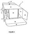
- recess panel 42 is then folded inwardly along fold line 98 through substantially 180° as illustrated by arrow X so as to partially overlie main receiving panel 44.
- Central bridging panel 40 is folded through substantially 90° in the opposite direction relative to recess panel 42, so as to be positioned substantially perpendicular to main receiving panel 44, spanning the space between the corresponding main bridging panel of he opposed receiving structure 38.
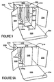
- a similar operation is carried out with the corresponding panels of receiving structure 38 such that bridging panels 40 and 110 are in substantially face contacting relationship as is shown in Figure 3.
- the bridging panels 40, 110 may optionally be secured together using glue or other suitable means known in the art.
- the base of the carton C is closed by folding base end flaps 28, 30 and base wall panel 26 inwardly out of alignment with corresponding end and side wall panels 12, 16 and 18.
- Securing flap 34 may be sandwiched between second side panel 16 and the non-glued portion of second securing panel 52.
- the bevelled portions 43, 45 of main receiving panel 44 and recessing panel 42 help to guide the flaps 34 between inner part and outer sleeves the location of the flap 34.
- the bridging panels 40, 110 impart rigidity to the carton whilst establishing an enclosed space between the bottom of Article A and the base of the carton.
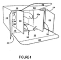
- transverse receiving panel 46 is folded outwardly along fold line 100, whilst end wall contacting panel 48 is, preferably, simultaneously folded in the opposite direction, the combination of both operations being represented by arrow Y.
- panel 48 is placed in a face contacting relationship with end wall panel 18, and transverse panel 46 spans the gap between main receiving panel 44 and end wall panel 18. By spanning the gap, the panel 48 acts as a brace to provide additional support to panel 44, thereby reducing unwanted internal movement.
- transverse panel 46 is dimensioned such that when panel 48 is brought into face contacting relationship with panel 18, transverse panel 44 is substantially perpendicular to both main receiving panel 44, and end wall contacting panel 48. This allows both panels 46 and 48 to be mechanically maintained in their desired position without the need for additional securing means.
- transverse panel may be dimensioned differently such that an acute or obtuse angle would exist between main receiving panel 44 and transverse receiving panel 46.
- glue or other securing means known in the art it would be preferable for glue or other securing means known in the art to be provided between panel 48 and end wall panel 18, so as to maintain the article receiving structure 36 in its set up condition.
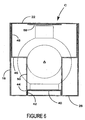
- Article receiving structure 38 is also set up in a similar manner, as is illustrated in Figure 5.
- the article A is then loaded into the carton C, and is held by the apertures 50, 50a provided in the article receiving structures 36, 38.
- Inner cover panel 56 is then folded inwardly along fold line 104 so as to overlie the top of article A.
- Securing flap 58 is folded along fold line 106 so as to be brought into face contacting relationship with second side panel 16.
- the carton is then closed by folding top end flaps 20 and 24, and top wall panel 22 inwardly along their respective fold lines 86, 80, 82 in a similar manner to the base wall panel end flaps of the base wall structure, as described above.
- Securing flap 32 is preferably held between an unsecured portion of third securing panel 54, and first side panel 12. Bevelled comer portions (not shown) similar to those described above could be included to guide securing flap 32 to the desired position.
- Figure 6 illustrates in cross sectional view the fully erected carton with article A loaded therein. It should be understood that the base and sides of the article A are spaced from the adjacent walls of the carton 12, 14, 16, 18, 26, but are held snugly such that substantially no movement of the article A within the carton is possible. It should be appreciated that the article receiving structures 36 and 38 provide one or more "crumple zone(s)" which may be deformed if there is an impact between the carton and another body, thus substantially absorbing the energy of such an impact without damaging the article A within. For example, the crumple zones may be provided by panels 42/44; 46 or 48.
- the caliper of the paperboard or like materials may be changed and/or the dimension of the panels and apertures adjusted such that a greater or lesser distance between the article and the walls of the carton may be provided.
- Figure 7A illustrates the inner sleeve 110a of a two part blank
- Figure 7B illustrates the outer sleeve 110b of a two part blank.
- Inner sleeve 110a is erected in a similar manner to inner sleeve 10a of the first embodiment however, glue G is applied to the same face of first support panel 162 as it is to second support panel 152 and third support panel 154.
- glue G is applied to the same face of first support panel 162 as it is to second support panel 152 and third support panel 154.
- first securing panel 162 is folded such that its free edge is brought into contact with the cut-away portion of third securing panel 154 as is defined by free edge 108 thereof.
- the shape of the cut-away portion, and first support panel may be altered within the scope of the invention.
- Outer sleeve 110b is erected in a similar manner to outer sleeve 10b of the first embodiment, the only difference being that an additional securing flap 119 is provided, being hingedly interconnected with second end panel 118 along fold 170.
- glue or other suitable means known in the art secures flap 119 to first side panel 112.
- the use of a two part blank allows the inner sleeve to be made from a differing grade and/or caliper of paperboard or like material from the outer sleeve, and furthermore simplifies the application of glue to the inner sleeve, as glue needs to be applied to one face of the blank only.
- FIG 8 there is shown another embodiment of the invention in which a carton is formed from a single blank 210 of paperboard or similar foldable sheet material adapted to accommodate an article such as a bottle, particularly a fragile article such as a bottle of perfume, for example.
- the blank could be two parts.
- the blank comprises two portions, outer sleeve 210b, and inner sleeve 210a.
- outer sleeve 210b the panels correspond substantially to the first embodiment and like references have been used with the prefix "2".
- first side wall panel 212 first end wall panel 214, second side wall panel 216 and second end wall panel 218 are hingedly interconnected in series along fold lines 264, 266 and 268 respectively.
- a top wall and base wall structure are provided that in this embodiment correspond substantially to the first embodiment and are not therefore described in any greater detail. It should be recognised that in alternative classes of embodiment other known end closure structures may be employed.
- inner sleeve portion 210a there is provided a plurality of panels for forming an article support structure.
- first securing panel 262 first article receiving structure 236, first intermediate panel 254, second article receiving structure 238, and second intermediate panel 252, hingedly interconnected in series along fold lines 288, 290, 292 and 294 respectively.
- First securing panel 262 is further hingedly connected to second side panel 218 of the outer sleeve 210a along fold line 270.
- Second article receiving structure 238 is, in this embodiment, substantially identical to the first article receiving structure except that in this embodiment structure 238 does not include an equivalent of bridging panel 240. Like panels are designated with the same numeral with the addition of the letter "a”. Therefore, only the first article receiving structure 236 is described in greater detail. Structure 236 preferably comprises central bridging panel 240, article receiving panel 244, transverse receiving panel 246 and upper panel 248 hingedly interconnected in series along fold lines 296, 298 and 200 respectively.
- an aperture 250 is provided in main receiving panels 244 for receiving the article A, once the blank has been erected to form a carton.
- the aperture 250 extends into transverse receiving panel 246.
- the size and shape of the aperture may be altered to receive differing articles.
- platform panel 251 formed from one of the panels forming the article retention structure.
- the platform panel 251 is struck from one or more of the main and transverse panels 244, 246.
- Figure 8 illustrates panel 251 is hingedly connected to an edge of aperture 250.
- platform panel 251 conforms to the shape of a portion of the article.
- a platform panel could be incorporated into the first or second embodiments.
- An inner cover panel 256 may be provided that is hingedly connected to intermediate panel 254. Securing flap 258 is further advantageously hingedly connected to inner cover panel 256 along fold line 306. There may also comprise spacer panel 255 hingedly connected to intermediate panel 254 along fold line 302 and to inner cover panel 256 along opposing fold line 304.
- glue is first applied to securing panel 262, to intermediate panels 252 and 254, and optionally to spacer panel 255.
- the inner sleeve is formed in like manner described above, whereby the panels forming the receiving structures are folded out of alignment to be placed in mutually opposed substantially parallel relationship, and first and second intermediate panels 254 and 252 are similarly placed in mutually opposed parallel relationship with the faces to which glue G has been applied facing outwardly. Thereafter, the outer sleeve panels 212, 214, 216 and 218 are now preferably folded out of mutual alignment so as to form an open ended tubular structure enclosing the partially erected inner sleeve 210b and is secured to the inner sleeve in like manner described above.
- the carton of this embodiment remains collapsible, and may optionally be supplied to the customer in collapsed form for subsequent complete erection on the customer's premises.
- the base structure is formed by folding central bridging panel 240 inwardly along fold line 296 through substantially 90° as illustrated by arrow Y so as to be positioned substantially perpendicular to main receiving panel 244, spanning the space between the opposed receiving structures 236, 238.
- the bridging panel 240 may optionally be secured to main receiving panel 244a using glue or other suitable means known in the art. In such embodiments, bridging panel 240 is advantageously provided with a securing flap that may be brought into contact with panel 244a.
- the base of the carton is illustrated in Figure 9A.
- the base of the carton is closed by folding base end flaps 228, 230 and base wall panel 226 inwardly out of alignment with corresponding end and side wall panels 214, 216 and 218 whereby panel 234 is sandwiched between first side panel 212 and a non-glued portion of second intermediate panel 252. Bevelled portions of main receiving panel 244 and recessing panel 242 may be provided to guide the flap 234 into position.
- Bridging panel 240 may advantageously be reduced in width so as not to engage first side panel 212, thereby assisting the function of the bevelled portions. As can be seen perhaps most clearly from Figure 9A, the bridging panel 240 imparts rigidity to the carton.
- transverse receiving panel 46 is folded outwardly along fold line 298, whilst upper panel 248 is preferably simultaneously folded in the opposite direction, the combination of both operations being represented by arrow Z.
- Upper panel 248 is placed in a face contacting relationship with end wall panel 218, and transverse panel 246 spans the gap between main receiving panel 244 and end wall panel 218 to provide a brace, similar to the first embodiment.
- transverse panel 246 is dimensioned such that when panel 248 is brought into face contacting relationship with side panel 218, transverse panel 246 is substantially perpendicular to both main receiving panel 244, and end wall contacting panel 248. This allows both panels 246 and 248 to be mechanically maintained in their desired position without the need for additional securing means.
- transverse panel may be dimensioned differently such that an acute or obtuse angle would exist between main receiving panel 244 and transverse receiving panel 246.
- glue or other securing means known in the art it would be preferable for glue or other securing means known in the art to be provided between upper panel 248 and end wall panel 218, so as to maintain the article receiving structure 236 in its set up condition.
- Article receiving structure 238 is also set up in a similar manner, as is illustrated in Figure 10A.
- the article A (Figure 11) is loaded into the carton, and is held by the apertures 250, 250a provided in the article receiving structures.
- Platform panels 251 and 251a are folded along fold lines 249 and 249a respectively into a substantially horizontal plane to define a platform P upon which the article A rests, shown in Figure 11.
- the panels 252 and 251a abut the adjacent side wall to be engaged therewith by suitable means.
- the platform P provides additional rigidity to prevent unwanted movement of the side walls and main receiving panels, and also substantially prevents the unprinted inner faces of the base, end and side wall panels being visible to the end user of the carton, when viewed from above.
- inner cover panel 256 is then preferably folded inwardly along fold line 204 so as to overlie the top of article A.
- Flap 258 is folded along fold line 206 so as to be brought into face contacting relationship with first side panel 216.
- the carton is then closed by folding top end flaps 220 and 224, and top wall panel 222 inwardly along their respective fold lines 286, 280, 282 in a similar manner to the base wall panel end flaps of the base wall structure, as described above.
- Tab 232 is preferably held between an unglued portion of spacer panel 255 or first intermediate panel 254, and first side panel 212 to complete the carton as shown in Figure 11.
- Figure 11A illustrates in cross sectional view the fully erected carton with article A loaded therein. It should be understood that the base and sides of the article A are spaced from the adjacent walls of the carton 212, 214, 216, 218, 226, but are held snugly such that substantially no movement of the article A within the carton is possible. It should be appreciated that the article receiving structures 236 and 238 provide a "crumple zone" which may be deformed if there is an impact between the carton and another body, thus substantially absorbing the energy of such an impact without damaging the article A within.
- the caliper of the paperboard or like materials may be changed and/or the dimension of the panels and apertures adjusted such that a greater or lesser distance between the article and the walls of the carton may be provided.
- hinged connection should not be construed as necessarily referring to a single fold line only: indeed it is envisaged that hinged connection can be formed from one or more of one of the following, a score line, a frangible line or a fold line, without departing from the scope of invention.
- the size and shape of the panels and apertures may be adjusted to accommodate articles of differing size or shape, alternative top and base closure structures may be used.
- a single article receiving structure may be provided in some embodiments, and in other embodiments a linear array of additional apertures may be provided in each of the article receiving structures such that the carton may accommodate more than one article.
- Additional panel(s) may be provided between the main and transverse article receiving panels so as to form a curved interface therebetween.
Landscapes
- Engineering & Computer Science (AREA)
- Mechanical Engineering (AREA)
- Cartons (AREA)
Applications Claiming Priority (3)
| Application Number | Priority Date | Filing Date | Title |
|---|---|---|---|
| GB9926565 | 1999-11-10 | ||
| GBGB9926565.4A GB9926565D0 (en) | 1999-11-10 | 1999-11-10 | Carton and carton blanks |
| EP00979146A EP1237790B1 (de) | 1999-11-10 | 2000-11-10 | Kartonbehälter und zuschnitt |
Related Parent Applications (1)
| Application Number | Title | Priority Date | Filing Date |
|---|---|---|---|
| EP00979146A Division EP1237790B1 (de) | 1999-11-10 | 2000-11-10 | Kartonbehälter und zuschnitt |
Publications (1)
| Publication Number | Publication Date |
|---|---|
| EP1528005A1 true EP1528005A1 (de) | 2005-05-04 |
Family
ID=10864246
Family Applications (1)
| Application Number | Title | Priority Date | Filing Date |
|---|---|---|---|
| EP04024690A Withdrawn EP1528005A1 (de) | 1999-11-10 | 2000-11-10 | Kartonbehälter und Kartonzuschnitte |
Country Status (2)
| Country | Link |
|---|---|
| EP (1) | EP1528005A1 (de) |
| GB (2) | GB9926565D0 (de) |
Families Citing this family (1)
| Publication number | Priority date | Publication date | Assignee | Title |
|---|---|---|---|---|
| CN115743855A (zh) * | 2022-11-24 | 2023-03-07 | 徐国新 | 一种纸箱防摔抗压结构 |
Citations (4)
| Publication number | Priority date | Publication date | Assignee | Title |
|---|---|---|---|---|
| US2732123A (en) | 1956-01-24 | bolding | ||
| US3547256A (en) | 1969-04-21 | 1970-12-15 | Eastex Packaging Inc | Package for lightbulbs and the like |
| US3693866A (en) | 1971-10-27 | 1972-09-26 | Diamond Int Corp | Shipping carton for fragile articles and blank for producing the same |
| EP0699588A1 (de) | 1994-08-25 | 1996-03-06 | Cd Cartondruck Gmbh | Faltpackung für Waren |
-
1999
- 1999-11-10 GB GBGB9926565.4A patent/GB9926565D0/en not_active Ceased
- 1999-12-23 GB GBGB9930489.1A patent/GB9930489D0/en not_active Ceased
-
2000
- 2000-11-10 EP EP04024690A patent/EP1528005A1/de not_active Withdrawn
Patent Citations (4)
| Publication number | Priority date | Publication date | Assignee | Title |
|---|---|---|---|---|
| US2732123A (en) | 1956-01-24 | bolding | ||
| US3547256A (en) | 1969-04-21 | 1970-12-15 | Eastex Packaging Inc | Package for lightbulbs and the like |
| US3693866A (en) | 1971-10-27 | 1972-09-26 | Diamond Int Corp | Shipping carton for fragile articles and blank for producing the same |
| EP0699588A1 (de) | 1994-08-25 | 1996-03-06 | Cd Cartondruck Gmbh | Faltpackung für Waren |
Also Published As
| Publication number | Publication date |
|---|---|
| GB9930489D0 (en) | 2000-02-16 |
| GB9926565D0 (en) | 2000-01-12 |
Similar Documents
| Publication | Publication Date | Title |
|---|---|---|
| US7073705B2 (en) | Carton with a glued insert and a blank combination for forming the same | |
| US6789678B2 (en) | Carton for fragile article | |
| US4784266A (en) | Means for stabilizing articles in multiple article packages | |
| US7234596B2 (en) | Carton and carton blank | |
| US6598784B2 (en) | Beverage carton with strap type carrying handle | |
| EP1334043A1 (de) | Karton und kartonzuschnitt | |
| EP1309491A2 (de) | Karton und zuschnitt dafür | |
| WO2002030764A9 (en) | Carton and carton blanks | |
| US6666333B2 (en) | Carton and carton blank | |
| EP1237790B1 (de) | Kartonbehälter und zuschnitt | |
| CA2454630C (en) | Carton and insert and blank for forming the same | |
| US6945390B2 (en) | Article carrier with handle-reinforcing bridging structure | |
| NZ254665A (en) | Bottle carrier having foldable corner web structures for gripping the bottle necks in a taut fashion | |
| EP1528005A1 (de) | Kartonbehälter und Kartonzuschnitte | |
| AU2001279220A1 (en) | Carton and insert and blank for forming the same | |
| EP1125850B1 (de) | Kartonbehälter und Zuschnitt | |
| EP1456088A1 (de) | Karton und kartonzuschnitt | |
| US6866144B2 (en) | Carton and carton blank | |
| EP1533246A2 (de) | Karton und Zuschnitt dafür | |
| EP1409356B1 (de) | Behälter für zerbrechliche gegenstände sowie entsprechender zuschnitt | |
| EP1268303B1 (de) | Artikelträger und zuschnitt | |
| EP1309492A1 (de) | Artikelträger und zuschnitt | |
| GB2381259A (en) | Tubular carton | |
| WO2001023270A1 (en) | Article carrier and blank therefor |
Legal Events
| Date | Code | Title | Description |
|---|---|---|---|
| PUAI | Public reference made under article 153(3) epc to a published international application that has entered the european phase |
Free format text: ORIGINAL CODE: 0009012 |
|
| 17P | Request for examination filed |
Effective date: 20041015 |
|
| AC | Divisional application: reference to earlier application |
Ref document number: 1237790 Country of ref document: EP Kind code of ref document: P |
|
| AK | Designated contracting states |
Kind code of ref document: A1 Designated state(s): AT BE CH CY DE DK ES FI FR GB GR IE IT LI LU MC NL PT SE TR |
|
| AKX | Designation fees paid |
Designated state(s): AT BE CH CY DE DK ES FI FR GB GR IE IT LI LU MC NL PT SE TR |
|
| RAP1 | Party data changed (applicant data changed or rights of an application transferred) |
Owner name: MEADWESTVACO PACKAGING SYSTEMS LLC |
|
| 17Q | First examination report despatched |
Effective date: 20080514 |
|
| STAA | Information on the status of an ep patent application or granted ep patent |
Free format text: STATUS: THE APPLICATION IS DEEMED TO BE WITHDRAWN |
|
| 18D | Application deemed to be withdrawn |
Effective date: 20090925 |