EP1527994A1 - Klimatisierungssystem und Verfahren zur Aufbereitung von Luft zur Klimatisierung eines Raumes - Google Patents
Klimatisierungssystem und Verfahren zur Aufbereitung von Luft zur Klimatisierung eines Raumes Download PDFInfo
- Publication number
- EP1527994A1 EP1527994A1 EP04009312A EP04009312A EP1527994A1 EP 1527994 A1 EP1527994 A1 EP 1527994A1 EP 04009312 A EP04009312 A EP 04009312A EP 04009312 A EP04009312 A EP 04009312A EP 1527994 A1 EP1527994 A1 EP 1527994A1
- Authority
- EP
- European Patent Office
- Prior art keywords
- air
- heat exchanger
- conditioning system
- turbine
- ram
- Prior art date
- Legal status (The legal status is an assumption and is not a legal conclusion. Google has not performed a legal analysis and makes no representation as to the accuracy of the status listed.)
- Granted
Links
- 238000000034 method Methods 0.000 title claims abstract description 19
- 230000003750 conditioning effect Effects 0.000 title abstract 2
- 230000007613 environmental effect Effects 0.000 title description 2
- 239000003570 air Substances 0.000 claims description 225
- 238000004378 air conditioning Methods 0.000 claims description 79
- 238000001816 cooling Methods 0.000 claims description 39
- 239000012080 ambient air Substances 0.000 claims description 28
- 239000002826 coolant Substances 0.000 claims description 12
- XLYOFNOQVPJJNP-UHFFFAOYSA-N water Substances O XLYOFNOQVPJJNP-UHFFFAOYSA-N 0.000 claims description 11
- 238000007639 printing Methods 0.000 claims description 10
- 238000000926 separation method Methods 0.000 claims description 10
- 238000004891 communication Methods 0.000 claims description 9
- 238000011144 upstream manufacturing Methods 0.000 claims description 9
- 230000008569 process Effects 0.000 claims description 4
- 238000009825 accumulation Methods 0.000 claims description 2
- 230000001105 regulatory effect Effects 0.000 claims description 2
- 230000001143 conditioned effect Effects 0.000 claims 2
- 230000008901 benefit Effects 0.000 description 6
- 230000006835 compression Effects 0.000 description 6
- 238000007906 compression Methods 0.000 description 6
- 230000035699 permeability Effects 0.000 description 5
- 238000011084 recovery Methods 0.000 description 5
- 238000010438 heat treatment Methods 0.000 description 3
- 102100032381 Alpha-hemoglobin-stabilizing protein Human genes 0.000 description 2
- 101000797984 Homo sapiens Alpha-hemoglobin-stabilizing protein Proteins 0.000 description 2
- 101150078761 MHX gene Proteins 0.000 description 2
- 238000007791 dehumidification Methods 0.000 description 2
- 239000012530 fluid Substances 0.000 description 2
- 238000012958 reprocessing Methods 0.000 description 2
- 238000010079 rubber tapping Methods 0.000 description 2
- 101100183893 Arabidopsis thaliana MHX gene Proteins 0.000 description 1
- 101000912352 Homo sapiens Putative uncharacterized protein DANCR Proteins 0.000 description 1
- 101100183890 Oryza sativa subsp. japonica MHX1 gene Proteins 0.000 description 1
- 101100183891 Oryza sativa subsp. japonica MHX2 gene Proteins 0.000 description 1
- 102100026242 Putative uncharacterized protein DANCR Human genes 0.000 description 1
- 230000000712 assembly Effects 0.000 description 1
- 238000000429 assembly Methods 0.000 description 1
- 230000000740 bleeding effect Effects 0.000 description 1
- 230000008859 change Effects 0.000 description 1
- 238000010276 construction Methods 0.000 description 1
- 230000003247 decreasing effect Effects 0.000 description 1
- 230000001419 dependent effect Effects 0.000 description 1
- 230000008021 deposition Effects 0.000 description 1
- 238000013461 design Methods 0.000 description 1
- 238000011161 development Methods 0.000 description 1
- 230000000694 effects Effects 0.000 description 1
- 238000012423 maintenance Methods 0.000 description 1
- 238000005259 measurement Methods 0.000 description 1
- 239000000203 mixture Substances 0.000 description 1
- 238000012986 modification Methods 0.000 description 1
- 230000004048 modification Effects 0.000 description 1
- 238000010248 power generation Methods 0.000 description 1
- 230000003134 recirculating effect Effects 0.000 description 1
- 239000013589 supplement Substances 0.000 description 1
Images




Classifications
-
- B—PERFORMING OPERATIONS; TRANSPORTING
- B64—AIRCRAFT; AVIATION; COSMONAUTICS
- B64D—EQUIPMENT FOR FITTING IN OR TO AIRCRAFT; FLIGHT SUITS; PARACHUTES; ARRANGEMENT OR MOUNTING OF POWER PLANTS OR PROPULSION TRANSMISSIONS IN AIRCRAFT
- B64D13/00—Arrangements or adaptations of air-treatment apparatus for aircraft crew or passengers, or freight space
- B64D13/06—Arrangements or adaptations of air-treatment apparatus for aircraft crew or passengers, or freight space the air being conditioned
-
- F—MECHANICAL ENGINEERING; LIGHTING; HEATING; WEAPONS; BLASTING
- F25—REFRIGERATION OR COOLING; COMBINED HEATING AND REFRIGERATION SYSTEMS; HEAT PUMP SYSTEMS; MANUFACTURE OR STORAGE OF ICE; LIQUEFACTION SOLIDIFICATION OF GASES
- F25B—REFRIGERATION MACHINES, PLANTS OR SYSTEMS; COMBINED HEATING AND REFRIGERATION SYSTEMS; HEAT PUMP SYSTEMS
- F25B9/00—Compression machines, plants or systems, in which the refrigerant is air or other gas of low boiling point
- F25B9/002—Compression machines, plants or systems, in which the refrigerant is air or other gas of low boiling point characterised by the refrigerant
- F25B9/004—Compression machines, plants or systems, in which the refrigerant is air or other gas of low boiling point characterised by the refrigerant the refrigerant being air
-
- B—PERFORMING OPERATIONS; TRANSPORTING
- B64—AIRCRAFT; AVIATION; COSMONAUTICS
- B64D—EQUIPMENT FOR FITTING IN OR TO AIRCRAFT; FLIGHT SUITS; PARACHUTES; ARRANGEMENT OR MOUNTING OF POWER PLANTS OR PROPULSION TRANSMISSIONS IN AIRCRAFT
- B64D13/00—Arrangements or adaptations of air-treatment apparatus for aircraft crew or passengers, or freight space
- B64D13/06—Arrangements or adaptations of air-treatment apparatus for aircraft crew or passengers, or freight space the air being conditioned
- B64D2013/0603—Environmental Control Systems
- B64D2013/0618—Environmental Control Systems with arrangements for reducing or managing bleed air, using another air source, e.g. ram air
-
- B—PERFORMING OPERATIONS; TRANSPORTING
- B64—AIRCRAFT; AVIATION; COSMONAUTICS
- B64D—EQUIPMENT FOR FITTING IN OR TO AIRCRAFT; FLIGHT SUITS; PARACHUTES; ARRANGEMENT OR MOUNTING OF POWER PLANTS OR PROPULSION TRANSMISSIONS IN AIRCRAFT
- B64D13/00—Arrangements or adaptations of air-treatment apparatus for aircraft crew or passengers, or freight space
- B64D13/06—Arrangements or adaptations of air-treatment apparatus for aircraft crew or passengers, or freight space the air being conditioned
- B64D2013/0603—Environmental Control Systems
- B64D2013/064—Environmental Control Systems comprising more than one system, e.g. dual systems
-
- B—PERFORMING OPERATIONS; TRANSPORTING
- B64—AIRCRAFT; AVIATION; COSMONAUTICS
- B64D—EQUIPMENT FOR FITTING IN OR TO AIRCRAFT; FLIGHT SUITS; PARACHUTES; ARRANGEMENT OR MOUNTING OF POWER PLANTS OR PROPULSION TRANSMISSIONS IN AIRCRAFT
- B64D13/00—Arrangements or adaptations of air-treatment apparatus for aircraft crew or passengers, or freight space
- B64D13/06—Arrangements or adaptations of air-treatment apparatus for aircraft crew or passengers, or freight space the air being conditioned
- B64D2013/0603—Environmental Control Systems
- B64D2013/0644—Environmental Control Systems including electric motors or generators
-
- B—PERFORMING OPERATIONS; TRANSPORTING
- B64—AIRCRAFT; AVIATION; COSMONAUTICS
- B64D—EQUIPMENT FOR FITTING IN OR TO AIRCRAFT; FLIGHT SUITS; PARACHUTES; ARRANGEMENT OR MOUNTING OF POWER PLANTS OR PROPULSION TRANSMISSIONS IN AIRCRAFT
- B64D13/00—Arrangements or adaptations of air-treatment apparatus for aircraft crew or passengers, or freight space
- B64D13/06—Arrangements or adaptations of air-treatment apparatus for aircraft crew or passengers, or freight space the air being conditioned
- B64D2013/0603—Environmental Control Systems
- B64D2013/0648—Environmental Control Systems with energy recovery means, e.g. using turbines
-
- B—PERFORMING OPERATIONS; TRANSPORTING
- B64—AIRCRAFT; AVIATION; COSMONAUTICS
- B64D—EQUIPMENT FOR FITTING IN OR TO AIRCRAFT; FLIGHT SUITS; PARACHUTES; ARRANGEMENT OR MOUNTING OF POWER PLANTS OR PROPULSION TRANSMISSIONS IN AIRCRAFT
- B64D13/00—Arrangements or adaptations of air-treatment apparatus for aircraft crew or passengers, or freight space
- B64D13/06—Arrangements or adaptations of air-treatment apparatus for aircraft crew or passengers, or freight space the air being conditioned
- B64D2013/0603—Environmental Control Systems
- B64D2013/0688—Environmental Control Systems with means for recirculating cabin air
-
- Y—GENERAL TAGGING OF NEW TECHNOLOGICAL DEVELOPMENTS; GENERAL TAGGING OF CROSS-SECTIONAL TECHNOLOGIES SPANNING OVER SEVERAL SECTIONS OF THE IPC; TECHNICAL SUBJECTS COVERED BY FORMER USPC CROSS-REFERENCE ART COLLECTIONS [XRACs] AND DIGESTS
- Y02—TECHNOLOGIES OR APPLICATIONS FOR MITIGATION OR ADAPTATION AGAINST CLIMATE CHANGE
- Y02T—CLIMATE CHANGE MITIGATION TECHNOLOGIES RELATED TO TRANSPORTATION
- Y02T50/00—Aeronautics or air transport
- Y02T50/50—On board measures aiming to increase energy efficiency
Definitions
- the invention relates to an air conditioning system, in particular an air conditioning system for the air conditioning of a passenger cabin of an aircraft after the The preamble of claim 1.
- the invention further relates to a method for Treatment of air for air conditioning of a room, in particular for air conditioning a passenger cabin of an airplane.
- Air conditioning systems for aircraft are in many different embodiments known. They are used in particular for heating and cooling the cabin, the cabin printing and the fresh air supply. Significant is that the air conditioning system on the smallest possible size and weight, which is of great interest, especially in aircraft construction.
- Previous air conditioning systems usually have a compressor and a turbine comprising shaft means, which additionally with a in A ram air duct arranged blower can be provided.
- the ram air channel are in prior art systems one or more heat exchangers, the compressed air used for cooling by the engines or auxiliary equipment serve.
- the compressed air is first in a first Heat exchanger cooled in the ram air channel, then in the compressor of the shaft device compressed, in a second, arranged in the ram air duct heat exchanger cooled again and then fed to a Wasserabscheideniklauf. Subsequently, the dehumidified air flows through the turbine of the Shaft device and then a mixing chamber or the passenger cabin fed.
- the air conditioning system disclosed in this document has at least one arranged in a ram air duct heat exchanger for cooling of compressed air.
- the heat exchanger comprises at least a first and a thereof compressed air side separate second heat exchanger unit, each of which one compressed air side communicates with one of the shaft devices in each case.
- the shaft devices have compressors on the outlet side with the compressed air side Inlet of the compressed air side separate heat exchanger units in conjunction stand.
- the heat exchanger units each have their own Compressed air supply.
- At least two heat exchanger units are a common ram air inlet channel and fluidically separate ram air outlet channels intended.
- the compressor inlet side with congestion or Ambient air are applied and that one or more motors provided are by means of which the compressors are driven.
- the compressors thus no air drawn from the engines, but only Stagnation or ambient air supplied compressed in the compressors and then the respective heat exchanger unit is supplied.
- the Engines are required to provide the power provided by a flash stage to supplement the compressor or in the case of bypass of the expansion stage to ensure the operation of the compressors.
- the air conditioning system according to the invention has in a preferred embodiment the advantage that it gets by without any bleed air from the engines.
- the system is only supplied with congestion or ambient air and that as well as reprocessing air for air conditioning of the room as well as cooling medium for the air to be treated.
- the heat exchanger units form a structural unit. They are in the common ram air channel arranged.
- a common ram air inlet channel is provided, for the purpose of modification the ram air flow and thus the cooling capacity of the heat exchanger units an adjustable in position ram air duct inlet flap provided can be.
- a common ram air outlet channel is provided.
- one, two or more motor-driven blower be provided. These ensure in ground operation for the maintenance of a flow through the ram air duct and provide the cooling capacity of the arranged in the ram air duct heat exchanger units for sure.
- the at least two heat exchanger units can provide separate ram air outlet channels. It can in each of the separate and immediately on the outlet side of the heat exchanger units beginning ram air outlet channels on or preferably two or more motor-driven blower be arranged.
- the blowers can be separated from each other in terms of flow mechanics be arranged of the ram air outlet channel.
- This fluid mechanical Separation of the ram air outlet duct preferably only relates to a partial area the ram air outlet channel and advantageously not on the directly on the heat exchanger units adjacent area.
- the fan in operation will blow air over the standing fan and not promotes by the heat exchanger units can be provided be that downstream of the blower check valves are provided, which prevent in the sections of the ram air outlet duct supplied by the blowers a return flow takes place.
- ram air channel To increase the permeability of the ram air channel can be provided that one or more also provided with check valves Gebläsebypässe are arranged in the ram air channel. At least one bypass, for example, between the supplied by the respective blower sections of the ram air outlet channel be arranged.
- the compressors to multi-stage compressors of which the first stage inlet side with congestion or ambient air is applied and the last stage on the outlet side is in communication with the compressed air side inlet of the heat exchanger units.
- two-stage or multi-stage compressors can be used.
- the shaft means may comprise at least one compressor, a turbine as Relaxation level and have a motor.
- the motor for driving the compressors is thus preferably part of a wave device.
- each of the shaft devices is each with a Wasserabscheideniklauf in conjunction.
- the Wasserabscheidenik concept serve for dehumidification of the relaxation stage supplied air. in principle may also be provided that for the plurality of shaft means a common Wasserabscheideniklauf is provided.
- the cooling capacity is not through the relaxation stage, but in the essentially provided by the heat exchanger unit.
- a bypass of the Wasserabscheideniklaufes is possible because the air at relatively high altitudes is dry and therefore a water separation is not mandatory.
- sufficient cooling of the cabin air may additionally be provided that operated a cabin air circulation is arranged in the means for removing heat from the recirculating air are.
- the means for removing heat can be carried out arbitrarily. she may include a heat exchanger or an evaporator through which suitable coolant can be performed.
- This heat exchanger unit can be designed as a condenser and with to connect to the evaporator.
- the evaporator and the condenser can Be part of a closed coolant circuit.
- one or more are from the outlet side the heat exchanger units to the outlet side of the expansion stages extending bypass lines provided, each by means of a arranged therein Valves are shut off.
- the bypass lines are used at high altitudes to increase the permeability of the system. In this mode of operation can It may be necessary to use a bypass, in particular the Wasserabscheideniklaufes and / or the turbine to reduce the pressure loss of the compressor outlet air to be kept as low as possible. In this case, that will be in the heat exchanger units cooled air by means of the bypass, preferably downstream of the turbine, preferably fed downstream of the condenser of the Wasserabscheideniklaufes and then fed to a mixing chamber or passenger cabin.
- the turbine is on the inlet side with a a valve closable line with the cabin or one of these upstream Mixing chamber and the outlet side via a closable with a valve Conduit associated with the environment, wherein means are provided by the the turbine from the lines carrying compressed air in the compressor can be locked.
- the means may be implemented as valves in the turbine with the Wasserabscheideniklauf connecting inlet pipe and in the Turbine arranged with the mixing chamber or the cabin connecting exhaust pipe are.
- the present invention further relates to a process for the treatment of air for Air conditioning of a room, in particular for the air conditioning of a passenger cabin an aircraft according to claim 20.
- a first mode of operation The cooled in the heat exchanger units air is a Wasserabscheideniklauf fed, relaxed in a relaxation stage and in the air-conditioned Room or an upstream mixing chamber out.
- a second mode of operation that in the Heat exchanger units cooled air lower bypass of Wasserabscheideniklaufes and / or the relaxation stage directly in the air-conditioned Room or an upstream mixing chamber is performed.
- the first operating mode is preferably ground operation or at lower altitudes and the second mode of operation preferably in larger ones Apply altitudes.
- the cooling capacity for cooling the heat exchanger units supplied air By means of congestion or ambient air can by changing the position of a Ram air duct inlet flap and / or by changing the operation of im Stauluftauslasskanal arranged fans are controlled or regulated.
- the cabin air at least is partially recycled and subjected to a cooling process becomes.
- the cooling takes place by means of a cooling medium which is circulated is, wherein the cooling medium in one in the ram air duct of the air conditioning system arranged heat exchanger unit is removed heat.
- the temperature and pressure conditions are chosen such that the cooling medium condenses in the heat exchanger unit.
- the invention further relates to an air conditioning system, in particular an air conditioning system for air conditioning a passenger cabin of an aircraft with at least a arranged in a ram air duct heat exchanger with at least a with the heat exchanger on the compressed air side connected shaft device with at least one inlet side with congestion or ambient air acted upon Compressor and at least one turbine, with at least one engine to drive the compressor, with a turbine bypass line to the compressed air side Bypassing of the turbine and with at least one control device by means of which the air conditioning system is operable in a first mode of operation in which the compressed air in the turbine is relaxed, and in a second mode of operation operable in which the compressed air is predominantly or completely is guided through the turbine bypass line, wherein the control device with the engine is in communication and is designed such that the engine in the first operating mode is operated such that the engine power for cooling purposes and for printing, and in the second mode of operation is operated, that the engine power to compress the congestion or ambient air is used.
- an air conditioning system for air conditioning a passenger cabin of an aircraft
- the air conditioning system is after one of claims 1 to 19 executed.
- Such an air conditioning system has the advantage that the available engine power the compressor motor in particular in ground operation or at lower Altitudes is not largely unused, but predominantly or exclusively for cooling and for printing the cabin, i. to compress the traffic jams or ambient air is used.
- the engine can, for example, in the range from 80 to 100% of its maximum power.
- the cooling is through the relaxation of the corresponding compressed air in the turbine of the shaft device reached.
- the available engine power becomes substantially or exclusively for the compression of the ambient air to the cabin pressure level, i.e. used for cabin printing. Cooling in flight takes place through the ram air heat exchanger and through optional recirculation cooling.
- the air conditioning system has the advantage that the performance of the compressor motor also in ground operation or at lower altitudes predominantly or is used exclusively for cooling, so that the apparent from Fig. 2 cabin air circuits 100 are carried out with correspondingly reduced cooling capacity can.
- Another advantage results from the fact that in the first operating mode one of the turbine upstream Wasserabscheideniklauf is available, so that, for example Dehumidification is also possible in ground operation.
- the invention further relates to a method for the treatment of air for air conditioning a room, in particular for the air conditioning of a passenger cabin of a Aircraft, comprising the following steps: compressing ambient or Ram air in a motor driven compressor unit and supply the compressed air into a heat exchanger, cooling the heat exchanger supplied air through congestion or ambient air, wherein in a first operating mode relaxes the cooled in the heat exchanger air in a flash stage is, in a second mode of operation in the heat exchanger cooled air predominantly or completely in the bypass around the relaxation stage is performed, and wherein in the first operating mode, the engine power to Cooling purposes and is used for printing and in the second mode of operation the engine power used to compress the accumulated or ambient air becomes.
- the first operating mode can be provided that the cooling of the air through the or the stagnation air heat exchanger and by the relaxation of the compressed Air is done in the turbine.
- the second operating mode can be provided that the cooling of the air by the or the stagnation air heat exchanger and by a Circulating air cooling takes place.
- the available engine power mainly or exclusively for cooling purposes and for printing the Cabin or other room to be printed is used and that in the second operating mode, the available engine power is predominantly or exclusively for printing, that is .. for the compression of the ambient or ram air the level of the space to be printed, especially the cabin used becomes.
- the available engine power can in a further embodiment of the invention the Value of engine power correspond to the maximum altitude of the engine is to be applied when the turbine is operated in bypass, i. not to the drive of the compressor is available. In a preferred embodiment of the invention This operating condition determines the design of the compressor motor.
- the method may be configured according to any one of claims 20 to 25.
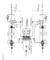
- Fig. 1 shows a schematic representation of an air conditioning system with two motorized shaft assemblies 20, 30, each consisting of a two-stage compressor 22, 32 of a turbine 24, 34 and an electric motor 26, 36 for supplementary Drive the compressor 22, 32 exist.
- the wave devices are in provided the figures with the name MACM.
- the air conditioning system further includes a common ram air channel 40, in which the compressed air side of each other separate heat exchanger units 12, 14th are arranged in the figures further with the designations MHX1 and MHX2 are designated. Between the heat exchanger units separated on the compressed air side 12, 14 is another heat exchanger unit 16, the compressed air side with none of the heat exchanger units 12 or 14 in conjunction and denoted by the symbols VCHX and VCCon in the figures is.
- the further heat exchanger unit 16 may be between the two Heat exchanger units 12, 14 are located or, for example, at the edge region the ram air channel 40 may be arranged.
- the arrangement of the heat exchanger units 12, 14, 16 is arbitrary.
- the heat exchanger units 12, 14, 16 form the heat exchanger 10th
- the blower 50, 52 Downstream of the heat exchanger are in the ram air outlet 44, the blower 50, 52 arranged, which in the figures also with the short names ERAF 1 and ERAF 2 are designated.
- the fans 50, 52 are powered by an electric motor driven.
- blowers 50, 52 are in fluid mechanical by walls separated from each other portions of the ram air outlet channel 44. Between these subregions is the blower bypass 60, which serves to increase the permeability during the flight. Downstream of Blower 50, 52 and in the outlet of the bypass channel 60 are the Check valves 54, 56 and 58.
- ram air channel inlet flap 43 On the inlet side of the ram air inlet channel 42 is the ram air channel inlet flap 43 (Duplex RAIA).
- the shaft devices are connected to the Wasserabscheidenikêttimn 70, 80 in Connection. These consist in a known manner from a reheater (REH), a Condenser (CON) and a water separator (WE).
- REH reheater
- CON Condenser
- WE water separator
- the reheaters are connected to the outlet sides of the heat exchanger units 12, 14 in connection.
- measuring elements Venturi for measuring the volume flow of the heat exchanger units 12, 14th leaving air.
- bypass lines 120, 130 are provided which from the outlet side of the heat exchanger units 12, 14 to the turbine outlet side extend and by means of a valve 122, 132 arranged therein (BPV) are lockable.
- BPV valve 122, 132 arranged therein
- the compressors 22, 32 are subjected to ambient or ram air.
- the compressor capacity on the one hand by the turbines 24, 34 and in addition of the Electric motors 26, 36 applied. These components together form one each the shaft means 20, 30.
- the compressed air flows separately into one the arranged in the common ram air duct 40 heat exchanger units 12, 14 and is therein by means of the guided into the ram air duct 40 congestion or ambient air cooled.
- the thus cooled air passes after passing through the flow meter (Venturi) in the reheater (REH) and then in the condenser (CON), in which the moisture in the air condenses out to a large extent becomes.
- the condensed water is in the water separator (WE) deposited.
- WE water separator
- the air is then passed through the reheater, while slightly heated and then relaxed in the turbines 24, 34. It will the air cooled down.
- the cooled air in this way is used to cool the Condenser (CON) and is heated slightly. It then arrives via a check valve in a mixing chamber or in the passenger cabin.
- the fans 50, 52 are driven by an electric motor and serve in ground operation to promote ambient air through the ram air duct 40.
- flight mode the flow through the ram air channel 40 due to the back pressure.
- bypass channel 60 is provided.
- the check valves 54, 56, 58 are provided.
- valves 122, 132 are opened to bypass a water separation circuit 70, 80 and the turbines 24, 34 by means of the bypass lines 120, 130 to ensure.
- the cooling is not done by means of the turbines 24, 34, but by means the heat exchanger units 12, 14, through which the air after its compression in the compressors 22, 32 flows.
- the air is then transferred via the bypass lines 120, 130 in the outlet lines of the turbines 24, 34 and in the inlet lines the mixing chamber or the passenger cabin out.
- the cooling without use of the turbines 24, 34 may be sufficient because the supplied ram air is very cold.
- Fig. 2 shows two of the air conditioning systems according to Fig. 1 with the names (AGU1 and AGU2).
- Fig. 2 further shows the upstream of the passenger cabin Mixing unit, into which the outlet air of the air conditioning system in accordance Fig. 1 is passed.
- the system of FIG. 2 thus includes 4 equivalent ones Fresh air supplies.
- the cabin air circuits 100 each include an evaporator 110, which together with the designed as a condenser heat exchanger units 16 forms part of a coolant circuit. It is intended that the coolant evaporates in the evaporator 110 and thereby the in the Circuit-guided cabin air removes heat. The vaporized coolant is in the heat exchanger unit 16 condenses and gives heat to the through the ram air channel 40 flowing ram air flow from.
- the shaft means may be arranged parallel to each other. Between The shaft devices may be the ram air channel. In the area next to the ram air inlet channel can the ram air or ambient air intakes for the shaft devices.
- the heat exchanger units can be arranged side by side in the flow direction be or over each other. Furthermore, it is possible to connect the shaft means to the heat exchanger units laterally or below the Heat exchanger units make. Of course, the reverse is true Arrangements with arranged above the heat exchanger units shaft means conceivable. Furthermore, it is also possible, as needed, the wave devices and the heat exchanger units are not orthogonal to each other but deviating from this, for example, to arrange at a 45 ° angle.
- each flow path the major components of each flow path are for fresh air to be treated, the motorized shaft device, the heat exchanger unit, a Wasserabscheideniklauf, the bypass line with bypass valve, the anti-icing valve, as well as the flow measurement.
- the common components of the fresh air paths are the ram air channel inlet flap, the ram air channel with check valves, the electrically operated blowers, the cooling system for the recirculated cabin air and a control system or control unit.
- Fig. 2 In order to ensure optimum Kabinentemperierung, those shown in Fig. 2 can electrical heaters may be provided, wherein per cabin area a heating device may be provided. In addition, can be provided be that hot compressed air is branched off downstream of the compressor.
- This air is then transferred via valves with the cold, from the mixing chamber to the passenger cabin mixed with flowing air.
- the required for the heating operation temperature increase of the fresh air is through achieved the compression in the compressors. As stated above, in addition electric heaters are used.
- the temperature control of the entire system takes place via the corresponding change the operation of the blower 50, 52 (in ground operation), on the open position the ram air duct inlet door 43, via the electrical heaters and by means of the cooling of the circulated cabin air.
- valve AIV is temporarily opened to hot Compressor outlet air to the outlet of the turbine to lead.
- FIG 4 shows a schematic representation of an air conditioning system according to FIG the invention using the cabin exhaust air.
- the cabin becomes in flight printed to the necessary environmental conditions for the people to reach. Increased due to the decreasing ambient altitude with the altitude the difference between cabin pressure and ambient pressure increases Altitude. The cabin air is directed to the ambient air by it is uselessly relaxed over the valves.
- Fig. 4 shows the use of such a system in an air conditioning system according to the present invention.
- the cabin exhaust air through a corresponding connection line to the inlet side of the turbine T. be guided. This line is by means of the valve CSOV (cabine shut off valve) shut off.
- CSOV cabin shut off valve
- shut-off valve TSOV turbine shut off valve
- CKV Check Valve
- the turbine T can be used for the Cabine Air Recovery.
- This cabin air flows over the opened valve CSOV into the turbine, there is relaxed and over the Outlet line with the open valve ASOV delivered to the environment.
- the closed valves TSOV and CKV prevent a mixture of cabin exhaust air with the fresh air to be supplied to the cabin.
- Fig. 2 shows an embodiment of the invention, in the per air conditioning system (AGU 1, 2) two heat exchanger units MHX 1, MHX 2 in a ram air duct are summarized.
- the resulting obvious system configurations are thus 2 or 2 + 2 or 2 + 2 + 2 etc. heat exchanger units.
- the invention is not limited to two heat exchanger units per ram air channel or limited per AGU. Rather, three or more than three heat exchanger units be provided. Basically, it is just as conceivable that only a heat exchanger unit, i. a heat exchanger is provided.
- the present invention can basically be implemented with one or two or more heat exchangers be executed. It can be provided that each of these Heat exchanger is arranged in a separate ram air channel. It can be provided be that each of the heat exchanger on the compressed air side with a shaft device communicates. It is also conceivable that two or more than two heat exchangers are arranged in a ram air channel.
- Fig. 5 shows a corresponding architecture, in which the ram air heat exchanger consists of three separate heat exchanger units, each of which on the compressed air side communicates with one of the shaft devices MACM, such as this is apparent from Fig. 5.
- Fig. 5 shows an architecture with three wave devices MACM.
- the shaft devices associated with the heat exchanger units may be identical or deviating from each other.
- Fig. 5 shows a system with three identical wave devices or identical interconnections the wave devices. The compressors of the shaft devices become subjected to accumulation or bypass air.
Landscapes
- Engineering & Computer Science (AREA)
- Physics & Mathematics (AREA)
- Mechanical Engineering (AREA)
- Thermal Sciences (AREA)
- General Engineering & Computer Science (AREA)
- Health & Medical Sciences (AREA)
- General Health & Medical Sciences (AREA)
- Pulmonology (AREA)
- Aviation & Aerospace Engineering (AREA)
- Air-Conditioning For Vehicles (AREA)
- Central Air Conditioning (AREA)
- Structures Of Non-Positive Displacement Pumps (AREA)
Abstract
Description
- Fig. 1:
- eine schematische Darstellung eines Klimatisierungssystems gemäß der Erfindung,
- Fig. 2:
- eine schematische Darstellung einer Klimatisierungsanlage mit zwei Klimatisierungssystemen gemäß Fig. 1,
- Fig. 3a:
- eine schematische Darstellung des Klimatisierungssystems gemäß Fig. 1 in einem ersten Betriebsmodus,
- Fig. 3b:
- eine schematische Darstellung des Klimatisierungssystems gemäß Fig. 1 in einem zweiten Betriebsmodus,
- Fig. 4:
- eine schematische Darstellung eines Klimatisierungssystems gemäß der Erfindung mit Nutzung der Kabinenabluft und
- Fig. 5:
- eine schematische Darstellung eines Klimatisierungssystems gemäß der Erfindung mit drei Stauluftwärmetauschern und drei Welleneinrichtungen.
Claims (30)
- Klimatisierungssystem, insbesondere Klimatisierungssystem zur Klimatisierung einer Passagierkabine eines Flugzeuges, mit wenigstens einem in einem Stauluftkanal (40) angeordneten Wärmetauscher (10) zur Kühlung von Druckluft sowie mit wenigstens einer ersten und einer zweiten Welleneinrichtung (20, 30), wobei der Wärmetauscher (10) wenigstens eine erste und eine davon druckluftseitig getrennte zweite Wärmetauschereinheit (12, 14) umfasst, die in dem gemeinsamen Stauluftkanal (40) angeordnet sind und von denen jeweils eine druckluftseitig mit jeweils einer der Welleneinrichtungen (20, 30) in Verbindung steht, wobei die Welleneinrichtungen (20, 30) Verdichter (22, 32) aufweisen, die auslassseitig jeweils mit dem druckluftseitigen Einlass der Wärmetauschereinheiten (12, 14) in Verbindung stehen,
dadurch gekennzeichnet, dass die Verdichter (22, 32) einlassseitig mit Stau- oder Umgebungsluft beaufschlagt werden und dass ein oder mehrere Motoren (26, 36) vorgesehen sind, mittels derer die Verdichter (22, 32) antreibbar sind. - Klimatisierungssystem nach Anspruch 1, dadurch gekennzeichnet, dass die Wärmetauschereinheiten (12, 14) eine bauliche Einheit bilden.
- Klimatisierungssystem nach Anspruch 1 oder 2, dadurch gekennzeichnet, dass für die wenigstens zwei Wärmetauschereinheiten (12, 14) ein gemeinsamer Staulufteinlasskanal (42) vorgesehen ist.
- Klimatisierungssystem nach Anspruch 3, dadurch gekennzeichnet, dass in dem Staulufteinlasskanal (42) eine in ihrer Position verstellbare Stauluftkanaleinlassklappe (43) vorgesehen ist.
- Klimatisierungssystem nach einem der vorhergehenden Ansprüche, dadurch gekennzeichnet, dass für die wenigstens zwei Wärmetauschereinheiten (12, 14) ein gemeinsamer Stauluftauslasskanal (44) vorgesehen ist.
- Klimatisierungssystem nach einem der vorhergehenden Ansprüche, dadurch gekennzeichnet, dass in dem Stauluftauslasskanal (44) ein, zwei oder mehr motorisch angetriebene Gebläse (50, 52) vorgesehen sind.
- Klimatisierungssystem nach Anspruch 6, dadurch gekennzeichnet, dass stromabwärts der Gebläse (50, 52) Rückschlagventile (54, 56) vorgesehen sind.
- Klimatisierungssystem nach einem der Ansprüche 5 bis 7, dadurch gekennzeichnet, dass in dem Stauluftauslasskanal (44) ein oder mehrere mit einem Rückschlagventil (58) versehene Gebläse-Bypässe (60) angeordnet sind.
- Klimatisierungssystem nach einem der vorhergehenden Ansprüche, dadurch gekennzeichnet, dass es sich bei den Verdichtern (22, 32) um mehrstufige Verdichter handelt, von denen die erste Stufe (22a, 32a) einlassseitig mit Stau- oder Umgebungsluft beaufschlagt wird und die letzte Stufe (22b, 32b) auslassseitig mit dem druckluftseitigen Einlass der Wärmetauschereinheiten (12, 14) in Verbindung steht.
- Klimatisierungssystem nach einem der vorhergehenden Ansprüche, dadurch gekennzeichnet, dass die Welleneinrichtungen (20, 30) wenigstens einen Verdichter (22, 32), Turbine (24, 34) sowie Motor (26, 36) aufweisen.
- Klimatisierungssystem nach einem der vorhergehenden Ansprüche, dadurch gekennzeichnet, dass jede der Welleneinrichtungen (20, 30) mit jeweils einem Wasserabscheidekreislauf (70, 80) in Verbindung steht.
- Klimatisierungssystem nach einem der vorhergehenden Ansprüche, dadurch gekennzeichnet, dass der Wärmetauscher (10) eine weitere mit Stau- oder Umgebungsluft beaufschlagbare Wärmetauschereinheit (16) aufweist, die mit der ersten sowie der zweiten Wärmetauschereinheit (12, 14) druckluftseitig nicht in Verbindung steht.
- Klimatisierungssystem nach einem der vorhergehenden Ansprüche, dadurch gekennzeichnet, dass ein Kabinenluftkreislauf (100) vorgesehen ist, in dem Mittel zur Abfuhr von Wärme aus der im Kreislauf geführten Luft angeordnet sind.
- Klimatisierungssystem nach Anspruch 13, dadurch gekennzeichnet, dass die Mittel einen Wärmetauscher umfassen.
- Klimatisierungssystem nach Anspruch 13, dadurch gekennzeichnet, dass die Mittel einen Verdampfer (110) umfassen.
- Klimatisierungssystem nach Anspruch 12 und 15, dadurch gekennzeichnet, dass die weitere in dem Stauluftkanal angeordnete Wärmetauschereinheit (16) als Kondensor ausgeführt ist und mit dem Verdampfer (110) in Verbindung steht, wobei die Wärmetauschereinheit (16) und der Verdampfer (110) Bestandteile eines Kühlmittelkreislaufes sind.
- Klimatisierungssystem nach einem der vorhergehenden Ansprüche, dadurch gekennzeichnet, dass eine oder mehrere sich von der Auslassseite der Wärmetauschereinheiten (12, 14) zu der Auslassseite der Turbinen (24, 34) erstreckende Bypassleitungen (120, 130) vorgesehen sind, die jeweils mittels eines darin angeordneten Ventils (122, 132) absperrbar sind.
- Klimatisierungssystem nach einem der vorhergehenden Ansprüchen, dadurch gekennzeichnet, dass die Turbine (T) einlassseitig über eine mit einem Ventil (CSOV) verschließbare Leitung mit der Kabine oder einer dieser vorgeschalteten Mischkammer und auslassseitig über eine mit einem Ventil (ASOV) verschließbare Leitung mit der Umgebung in Verbindung steht, und dass Mittel vorgesehen sind, durch die die Turbine (T) von den die in dem Kompressor (C) verdichtete Luft führenden Leitungen absperrbar ist.
- Klimatisierungssystem nach Anspruch 18, dadurch gekennzeichnet, dass die Mittel als Ventile (TSOV, CKV) ausgeführt sind, die in der die Turbine (T) mit dem Wasserabscheidekreislauf verbindenden Einlassleitung sowie in der die Turbine (T) mit der Mischkammer oder der Kabine verbindenden Auslassleitung angeordnet sind.
- Verfahren zur Aufbereitung von Luft zur Klimatisierung eines Raumes, insbesondere zur Klimatisierung einer Passagierkabine eines Flugzeuges, umfassend die folgenden Schritte:wobei in einem ersten Betriebsmodus die in den Wärmetauschereinheiten (12, 14) gekühlte Luft einem Wasserabscheidekreislauf (70, 80) zugeführt, in einer Entspannungsstufe (24, 34) entspannt und in den zu klimatisierenden Raum oder in eine vorgeschaltete Mischkammer geführt wird,Verdichten von Umgebungs- oder Stauluft in einer ersten motorisch angetriebenen Verdichtereinheit (22) und Zufuhr der verdichteten Luft in eine erste Wärmetauschereinheit (12) eines Wärmetauschers (10);Verdichten von Umgebungs- oder Stauluft in einer zweiten motorisch angetriebenen Verdichtereinheit (32) und Zufuhr der verdichteten Luft in eine zweite, von der ersten Wärmetauschereinheit (12) druckluftseitig getrennte Wärmetauschereinheit (14) des Wärmetauschers (10) undKühlung der den Wärmetauschereinheiten (12, 14) zugeführten Luft durch Stau- oder Umgebungsluft;
und wobei in einem zweiten Betriebsmodus die in den Wärmetauschereinheiten (12, 14) gekühlte Luft unter Umgehung des Wasserabscheidekreislaufes (70, 80) und/oder der Entspannungsstufe (24, 34) unmittelbar in den zu klimatisierenden Raum oder in eine vorgeschaltete Mischkammer geführt wird. - Verfahren nach Anspruch 20, dadurch gekennzeichnet, dass der erste Betriebsmodus des Verfahrens im Bodenbetrieb des Flugzeuges und in geringen Flughöhen des Flugzeuges und der zweite Betriebsmodus in demgegenüber größeren Flughöhen angewandt wird.
- Verfahren nach Anspruch 20 oder 21 dadurch gekennzeichnet, dass die Kühlleistung bei der Kühlung der den Wärmetauschereinheiten (12, 14) zugeführten Luft durch Stau- oder Umgebungsluft durch die Änderung der Position einer Stauluftkanaleinlassklappe (43) und/oder durch die Änderung der Leistung von im Stauluftauslasskanal (44) angeordneten Gebläsen (50, 52) gesteuert oder geregelt wird.
- Verfahren nach einem der Ansprüche 20 bis 22, dadurch gekennzeichnet, dass die Raumluft, insbesondere die Kabinenluft, zumindest teilweise im Kreislauf geführt wird und dabei gekühlt wird.
- Verfahren nach Anspruch 23, dadurch gekennzeichnet, dass die Kühlung mittels eines Kühlmediums erfolgt, das im Kreislauf geführt wird, und dass dem Kühlmedium in einer in dem Stauluftkanal (40) des Klimatisierungssystems angeordneten Wärmetauschereinheit (16) Wärme entzogen wird.
- Verfahren nach einem der vorhergehenden Ansprüche, dadurch gekennzeichnet, dass in dem zweiten Betriebsmodus Kabinenabluft in der Turbine (T) entspannt und sodann der Umgebungsluft zugeführt wird.
- Klimatisierungssystem, insbesondere Klimatisierungssystem zur Klimatisierung einer Passagierkabine eines Flugzeuges, mit wenigstens einem in einem Stauluftkanal angeordneten Wärmetauscher, mit wenigstens einer mit dem Wärmetauscher druckluftseitig in Verbindung stehenden Welleneinrichtung mit wenigstens einem einlassseitig mit Stau- oder Umgebungsluft beaufschlagten Verdichter und wenigstens einer Turbine, mit wenigstens einem Motor zum Antrieb des Verdichters, mit einer Turbinen-Bypassleitung zur druckluftseitigen Umgehung der Turbine sowie mit wenigstens einer Steuereinrichtung, mittels derer das Klimatisierungssystem in einem ersten Betriebsmodus betreibbar ist, in dem die verdichtete Luft in der Turbine entspannt wird, und in einem zweiten Betriebsmodus betreibbar ist, in dem die verdichtete Luft überwiegend oder vollständig durch die Turbinen-Bypassleitung geführt wird, wobei die Steuereinrichtung mit dem Motor in Verbindung steht und derart ausgeführt ist, dass der Motor in dem ersten Betriebsmodus derart betrieben wird, dass die Motorleistung für Kühlzwecke sowie zur Bedruckung verwendet wird, und in dem zweiten Betriebsmodus derart betrieben wird, dass die Motorleistung zur Verdichtung der Stau- oder Umgebungsluft verwendet wird.
- Klimatisierungssystem nach Anspruch 26, dadurch gekennzeichnet, dass die Steuereinrichtung derart ausgeführt ist, dass der erste Betriebsmodus im Bodenbetrieb und/oder bei geringen Flughöhen und der zweite Betriebsmodus bei demgegenüber größeren Flughöhen angewandt wird.
- Klimatisierungssystem nach Anspruch 26 oder 27, dadurch gekennzeichnet, dass das Klimatisierungssystem nach einem der Ansprüche 1 bis 19 ausgeführt ist.
- Verfahren zur Aufbereitung von Luft zur Klimatisierung eines Raumes, insbesondere zur Klimatisierung einer Passagierkabine eines Flugzeuges, umfassend die folgenden Schritte:Verdichten von Stau- oder Umgebungsluft in einer mittels eines Motors angetriebenen Verdichtereinheit und Zufuhr der verdichteten Luft in einen Wärmetauscher,Kühlung der dem Wärmetauscher zugeführten Luft durch Stau- oder Umgebungsluft,wobei in einem ersten Betriebsmodus die in dem Wärmetauscher gekühlte Luft in einer Entspannungsstufe entspannt wird,wobei in einem zweiten Betriebsmodus die in dem Wärmetauscher gekühlte Luft überwiegend oder vollständig im Bypass um die Entspannungsstufe geführt wird,und wobei in dem ersten Betriebsmodus die Motorleistung zu Kühlzwekken sowie zur Bedruckung verwendet wird und in dem zweiten Betriebsmodus die Motorleistung zur Verdichtung der Stau- oder Umgebungsluft verwendet wird.
- Verfahren nach Anspruch 29, dadurch gekennzeichnet, dass das Verfahren nach einem der Ansprüche 20 bis 25 ausgeführt ist.
Priority Applications (1)
| Application Number | Priority Date | Filing Date | Title |
|---|---|---|---|
| US10/977,250 US7467524B2 (en) | 2003-10-29 | 2004-10-29 | Air-conditioning system and a method for the preparation of air for the air-conditioning of a space |
Applications Claiming Priority (2)
| Application Number | Priority Date | Filing Date | Title |
|---|---|---|---|
| DE10350541A DE10350541A1 (de) | 2003-10-29 | 2003-10-29 | Klimatisierungssystem und Verfahren zur Aufbereitung von Luft zur Klimatisierung eines Raumes |
| DE10350541 | 2003-10-29 |
Publications (2)
| Publication Number | Publication Date |
|---|---|
| EP1527994A1 true EP1527994A1 (de) | 2005-05-04 |
| EP1527994B1 EP1527994B1 (de) | 2008-01-16 |
Family
ID=34399603
Family Applications (1)
| Application Number | Title | Priority Date | Filing Date |
|---|---|---|---|
| EP04009312A Expired - Lifetime EP1527994B1 (de) | 2003-10-29 | 2004-04-20 | Klimatisierungssystem und Verfahren zur Aufbereitung von Luft zur Klimatisierung eines Raumes |
Country Status (4)
| Country | Link |
|---|---|
| US (1) | US7467524B2 (de) |
| EP (1) | EP1527994B1 (de) |
| DE (2) | DE10350541A1 (de) |
| ES (1) | ES2297296T3 (de) |
Cited By (5)
| Publication number | Priority date | Publication date | Assignee | Title |
|---|---|---|---|---|
| EP1752377A3 (de) * | 2005-08-08 | 2007-03-07 | Liebherr-Aerospace Lindenberg GmbH | Verfahren zum Betreiben eines Flugzeugsystems |
| WO2012079756A3 (en) * | 2010-12-14 | 2012-08-23 | Airbus Operations Gmbh | Method and device for controlling an aircraft air conditioning system |
| EP2602191A1 (de) * | 2011-12-05 | 2013-06-12 | Hamilton Sundstrand Corporation | Motorbetriebener Kabinenluftkompressor mit verstellbarem Diffusor |
| WO2017107718A1 (zh) * | 2015-12-25 | 2017-06-29 | 广州亿航智能技术有限公司 | 多轴载人飞行器 |
| EP4286278A1 (de) * | 2022-06-01 | 2023-12-06 | Hamilton Sundstrand Corporation | Klimaregelungssystem ohne zapfluftbetriebene drossel |
Families Citing this family (30)
| Publication number | Priority date | Publication date | Assignee | Title |
|---|---|---|---|---|
| DE102006016541B4 (de) * | 2006-04-07 | 2014-05-22 | Airbus Operations Gmbh | Klimatisierungssystem für Flugzeuge |
| DE102006023444A1 (de) | 2006-05-18 | 2007-11-22 | Liebherr-Aerospace Lindenberg Gmbh | Klimaanlage mit einer redundanten Zuführung von Versorgungsluft |
| BRPI0719485A2 (pt) * | 2006-12-21 | 2014-02-18 | Airbus Gmbh | Sistema de arrefecimento para aeronave com base em ar comprimido e sistema de ar condicionado de cabine |
| DE102007004366A1 (de) * | 2007-01-29 | 2008-07-31 | Liebherr-Aerospace Lindenberg Gmbh | Klimatisierungssystem |
| US8973393B2 (en) * | 2009-11-08 | 2015-03-10 | The Boeing Company | System and method for improved cooling efficiency of an aircraft during both ground and flight operation |
| US8967528B2 (en) | 2012-01-24 | 2015-03-03 | The Boeing Company | Bleed air systems for use with aircrafts and related methods |
| US8955794B2 (en) | 2012-01-24 | 2015-02-17 | The Boeing Company | Bleed air systems for use with aircrafts and related methods |
| US10723463B1 (en) * | 2012-12-07 | 2020-07-28 | Wesley M. Plattner | Systems and methods for efficient operation of air cycle machines |
| US9617005B1 (en) * | 2013-07-31 | 2017-04-11 | Peter Schiff | System and method for replacing an engine powered air conditioning unit with an electric air conditioning unit in an aircraft |
| US9580180B2 (en) | 2014-03-07 | 2017-02-28 | Honeywell International Inc. | Low-pressure bleed air aircraft environmental control system |
| US10054051B2 (en) | 2014-04-01 | 2018-08-21 | The Boeing Company | Bleed air systems for use with aircraft and related methods |
| US9810158B2 (en) | 2014-04-01 | 2017-11-07 | The Boeing Company | Bleed air systems for use with aircraft and related methods |
| US10946969B2 (en) * | 2014-08-12 | 2021-03-16 | The Boeing Company | Split ventilation systems |
| FR3025497B1 (fr) * | 2014-09-05 | 2016-09-30 | Liebherr-Aerospace Toulouse Sas | Systeme de conditionnement d'air pour avion " plus electrique " |
| US10100744B2 (en) | 2015-06-19 | 2018-10-16 | The Boeing Company | Aircraft bleed air and engine starter systems and related methods |
| US10011361B2 (en) | 2015-11-16 | 2018-07-03 | Textron Innovations Inc. | Aircraft environmental control system providing improved performance and backup temperature control |
| WO2017112875A1 (en) * | 2015-12-22 | 2017-06-29 | Arizona Technology Enterprises | Systems, methods, and apparatuses for implementing a closed low grade heat driven cycle to produce shaft power and refrigeration |
| EP3187418A1 (de) * | 2015-12-30 | 2017-07-05 | Airbus Operations S.L. | Klimaanlagensystem |
| US10399683B2 (en) * | 2016-02-16 | 2019-09-03 | The Boeing Company | Thermal management systems and methods |
| US20170268837A1 (en) * | 2016-03-16 | 2017-09-21 | Hamilton Sundstrand Corporation | Pack-and-a-half architecture for environmental control systems |
| US10882623B2 (en) * | 2017-01-27 | 2021-01-05 | Hamilton Sunstrand Corporation | Advanced environmental control system in an integrated split pack arrangement with two bleed/outflow heat exchangers |
| US10384785B2 (en) | 2017-02-17 | 2019-08-20 | Hamilton Sundstrand Corporation | Two mode system that provides bleed and outside air or just outside air |
| US10086946B1 (en) * | 2017-04-03 | 2018-10-02 | Hamilton Sundstrand Corporation | Hybrid third air condition pack |
| US10526092B2 (en) * | 2017-04-03 | 2020-01-07 | Hamilton Sundstrand Corporation | Turbine-assisted cabin air compressor |
| US10954865B2 (en) | 2018-06-19 | 2021-03-23 | The Boeing Company | Pressurized air systems for aircraft and related methods |
| US11465757B2 (en) * | 2018-12-06 | 2022-10-11 | The Boeing Company | Systems and methods to produce aircraft cabin supply air |
| US11377217B2 (en) | 2019-06-11 | 2022-07-05 | Hamilton Sundstrand Corporation | Using bleed air to supply outside air to a cabin |
| US11332252B2 (en) | 2019-06-11 | 2022-05-17 | Hamilton Sundstrand Corporation | Using bleed air to supply outside air to a cabin |
| CN110723293B (zh) * | 2019-09-12 | 2023-01-10 | 中国商用飞机有限责任公司 | 辅助温度控制装置、温度调节系统和温度调节方法 |
| US11859885B2 (en) | 2021-07-23 | 2024-01-02 | Refrigerated Solutions Group Llc | Refrigerant circuit with reduced environmental impact |
Citations (6)
| Publication number | Priority date | Publication date | Assignee | Title |
|---|---|---|---|---|
| US4487034A (en) * | 1981-03-27 | 1984-12-11 | Lockheed Corporation | Energy-efficient all-electric ECS for aircraft |
| US4523517A (en) * | 1980-09-02 | 1985-06-18 | Lockhead Corporation | All electric environmental control system for advanced transport aircraft |
| EP0888966A2 (de) * | 1997-07-02 | 1999-01-07 | Boeing North American, Inc. | Hocheffizientes Klimaregelungssystem und Verfahren |
| EP0891279B1 (de) | 1996-04-08 | 2001-08-29 | United Technologies Corporation | Integriertes umgebungsluftregelsystem |
| US20020113167A1 (en) * | 2001-02-16 | 2002-08-22 | Jose Albero | Aircraft architecture with a reduced bleed aircraft secondary power system |
| DE10201426A1 (de) | 2002-01-16 | 2003-07-24 | Liebherr Aerospace Gmbh | Klimatisierungssystem |
Family Cites Families (16)
| Publication number | Priority date | Publication date | Assignee | Title |
|---|---|---|---|---|
| JPS5941438B2 (ja) | 1976-08-12 | 1984-10-06 | 株式会社島津製作所 | 航空機における空気調和装置 |
| US4963174A (en) * | 1989-12-12 | 1990-10-16 | Payne George K | Hybrid vapor cycle/air cycle environmental control system |
| JP2793079B2 (ja) * | 1992-05-25 | 1998-09-03 | 三洋電機株式会社 | 空気調和機 |
| DE4308630C1 (de) * | 1993-03-18 | 1994-08-04 | Hagenuk Fahrzeugklima Gmbh | Kombinierter Kühl- und Heizprozeß und Vorrichtung zur Klimatisierung eines Raumes |
| US5461882A (en) * | 1994-07-22 | 1995-10-31 | United Technologies Corporation | Regenerative condensing cycle |
| US6205803B1 (en) * | 1996-04-26 | 2001-03-27 | Mainstream Engineering Corporation | Compact avionics-pod-cooling unit thermal control method and apparatus |
| WO1999002401A1 (en) * | 1997-07-11 | 1999-01-21 | Alliedsignal Inc. | Air cycle environmental control system with vapor cycle system assisted condensation |
| US5956960A (en) * | 1997-09-08 | 1999-09-28 | Sundstrand Corporation | Multiple mode environmental control system for pressurized aircraft cabin |
| US6194452B1 (en) | 1997-11-07 | 2001-02-27 | Howard Murad | Stable pharmaceutical compositions including ascorbic acid and methods of using same |
| US6257003B1 (en) * | 2000-08-04 | 2001-07-10 | Hamilton Sundstrand Corporation | Environmental control system utilizing two air cycle machines |
| US6681592B1 (en) * | 2001-02-16 | 2004-01-27 | Hamilton Sundstrand Corporation | Electrically driven aircraft cabin ventilation and environmental control system |
| DE10139483B4 (de) | 2001-08-10 | 2005-06-23 | Liebherr-Aerospace Lindenberg Gmbh | Klimatisierungssystem |
| US6526775B1 (en) * | 2001-09-14 | 2003-03-04 | The Boeing Company | Electric air conditioning system for an aircraft |
| DE10201427A1 (de) * | 2002-01-16 | 2003-07-24 | Liebherr Aerospace Gmbh | System zur Luftentfeuchtung in Klimaanlagen |
| EP1492704B1 (de) * | 2002-04-08 | 2006-12-06 | Honeywell Normalair-Garrett (Holdings) Limited | Klimaanlage |
| US7000425B2 (en) * | 2003-03-12 | 2006-02-21 | Hamilton Sundstrand | Manifold for pack and a half condensing cycle pack with combined heat exchangers |
-
2003
- 2003-10-29 DE DE10350541A patent/DE10350541A1/de not_active Ceased
-
2004
- 2004-04-20 ES ES04009312T patent/ES2297296T3/es not_active Expired - Lifetime
- 2004-04-20 DE DE502004005951T patent/DE502004005951D1/de not_active Expired - Lifetime
- 2004-04-20 EP EP04009312A patent/EP1527994B1/de not_active Expired - Lifetime
- 2004-10-29 US US10/977,250 patent/US7467524B2/en not_active Expired - Lifetime
Patent Citations (6)
| Publication number | Priority date | Publication date | Assignee | Title |
|---|---|---|---|---|
| US4523517A (en) * | 1980-09-02 | 1985-06-18 | Lockhead Corporation | All electric environmental control system for advanced transport aircraft |
| US4487034A (en) * | 1981-03-27 | 1984-12-11 | Lockheed Corporation | Energy-efficient all-electric ECS for aircraft |
| EP0891279B1 (de) | 1996-04-08 | 2001-08-29 | United Technologies Corporation | Integriertes umgebungsluftregelsystem |
| EP0888966A2 (de) * | 1997-07-02 | 1999-01-07 | Boeing North American, Inc. | Hocheffizientes Klimaregelungssystem und Verfahren |
| US20020113167A1 (en) * | 2001-02-16 | 2002-08-22 | Jose Albero | Aircraft architecture with a reduced bleed aircraft secondary power system |
| DE10201426A1 (de) | 2002-01-16 | 2003-07-24 | Liebherr Aerospace Gmbh | Klimatisierungssystem |
Cited By (7)
| Publication number | Priority date | Publication date | Assignee | Title |
|---|---|---|---|---|
| EP1752377A3 (de) * | 2005-08-08 | 2007-03-07 | Liebherr-Aerospace Lindenberg GmbH | Verfahren zum Betreiben eines Flugzeugsystems |
| US7797962B2 (en) | 2005-08-08 | 2010-09-21 | Liebherr-Aerospace Lindenberg Gmbh | Method of operating an aircraft system |
| WO2012079756A3 (en) * | 2010-12-14 | 2012-08-23 | Airbus Operations Gmbh | Method and device for controlling an aircraft air conditioning system |
| US10071807B2 (en) | 2010-12-14 | 2018-09-11 | Airbus Operations Gmbh | Method and device for controlling an aircraft air conditioning system |
| EP2602191A1 (de) * | 2011-12-05 | 2013-06-12 | Hamilton Sundstrand Corporation | Motorbetriebener Kabinenluftkompressor mit verstellbarem Diffusor |
| WO2017107718A1 (zh) * | 2015-12-25 | 2017-06-29 | 广州亿航智能技术有限公司 | 多轴载人飞行器 |
| EP4286278A1 (de) * | 2022-06-01 | 2023-12-06 | Hamilton Sundstrand Corporation | Klimaregelungssystem ohne zapfluftbetriebene drossel |
Also Published As
| Publication number | Publication date |
|---|---|
| US7467524B2 (en) | 2008-12-23 |
| US20050188716A1 (en) | 2005-09-01 |
| EP1527994B1 (de) | 2008-01-16 |
| DE502004005951D1 (de) | 2008-03-06 |
| DE10350541A1 (de) | 2005-06-16 |
| ES2297296T3 (es) | 2008-05-01 |
Similar Documents
| Publication | Publication Date | Title |
|---|---|---|
| EP1527994B1 (de) | Klimatisierungssystem und Verfahren zur Aufbereitung von Luft zur Klimatisierung eines Raumes | |
| DE19963280C1 (de) | Klimatisierungssystem für Flugzeugkabinen | |
| EP1752377B1 (de) | Verfahren zum Betreiben eines Flugzeugsystems | |
| DE69821134T2 (de) | Zweiwellenklimaanlage | |
| DE69502501T2 (de) | Regenerativer kondensierkreislauf | |
| DE102007057536B4 (de) | Klimaanlage mit Hybrid-Zapfluft-Betrieb | |
| EP1329380B1 (de) | Klimatisierungssystem | |
| DE60111976T2 (de) | Luftkreislauf- Klimaregelungssystem | |
| EP1190946B1 (de) | Klimatisierungssystem für Flugzeuge | |
| DE60110426T2 (de) | Klimatisierungssystem mit zwei air-cycle-maschinen | |
| DE102006042584B4 (de) | Luftzufuhrsystem eines Flugzeuges sowie Verfahren zum Vermischen zweier Luftströme in einem Luftzufuhrsystem | |
| DE2336500C3 (de) | Vorrichtung zur Klimatisierung von Luftfahrzeugkabinen | |
| DE60310216T2 (de) | Klimaanlage | |
| DE102015222193A1 (de) | Flugzeugklimaanlage mit einer Kabinenabluftturbine | |
| DE102010021890A1 (de) | Klimatisierungssystem für ein Flugzeug mit Hybrid-Betrieb | |
| EP1176090B1 (de) | Klimatisierungssystem für Flugzeuge | |
| EP1329381A1 (de) | Luftentfeuchtung in Luftkreislauf-Klimaanlagen | |
| DE102016204911A1 (de) | Flugzeugklimaanlage mit einem elektrisch angetriebenen Umgebungsluftkompressor und Verfahren zum Betreiben einer derartigen Flugzeugklimaanlage | |
| EP2340202A1 (de) | System und verfahren zur klimatisierung einer flugzeugkabine mit verbesserter kühlleistung | |
| DE10139483B4 (de) | Klimatisierungssystem | |
| DE102015223548A1 (de) | Flugzeugklimaanlage mit Umgebungsluftzufuhr und Verfahren zum Betreiben einer derartigen Flugzeugklimaanlage | |
| DE102016223531B4 (de) | Kabinenabluftunterstützt betreibbare Flugzeugklimaanlage mit einem pneumatisch angetriebenen Umgebungsluftkompressor | |
| DE19935918A1 (de) | Klimatisierungssystem für Flugzeugkabinen | |
| DE102016223528B4 (de) | Kabinenabluftunterstützt betreibbare Flugzeugklimaanlage mit einem elektrisch angetriebenen Umgebungsluftkompressor | |
| DE69403448T2 (de) | Luftklimatisierung und unterdrucksetzungverfahren und anlage für einen teilweise gesclossenenen raum |
Legal Events
| Date | Code | Title | Description |
|---|---|---|---|
| PUAI | Public reference made under article 153(3) epc to a published international application that has entered the european phase |
Free format text: ORIGINAL CODE: 0009012 |
|
| 17P | Request for examination filed |
Effective date: 20040420 |
|
| AK | Designated contracting states |
Kind code of ref document: A1 Designated state(s): AT BE BG CH CY CZ DE DK EE ES FI FR GB GR HU IE IT LI LU MC NL PL PT RO SE SI SK TR |
|
| AX | Request for extension of the european patent |
Extension state: AL HR LT LV MK |
|
| AKX | Designation fees paid |
Designated state(s): DE ES FR GB IT |
|
| 17Q | First examination report despatched |
Effective date: 20050817 |
|
| GRAP | Despatch of communication of intention to grant a patent |
Free format text: ORIGINAL CODE: EPIDOSNIGR1 |
|
| GRAS | Grant fee paid |
Free format text: ORIGINAL CODE: EPIDOSNIGR3 |
|
| GRAA | (expected) grant |
Free format text: ORIGINAL CODE: 0009210 |
|
| AK | Designated contracting states |
Kind code of ref document: B1 Designated state(s): DE ES FR GB IT |
|
| REG | Reference to a national code |
Ref country code: GB Ref legal event code: FG4D Free format text: NOT ENGLISH |
|
| REF | Corresponds to: |
Ref document number: 502004005951 Country of ref document: DE Date of ref document: 20080306 Kind code of ref document: P |
|
| REG | Reference to a national code |
Ref country code: ES Ref legal event code: FG2A Ref document number: 2297296 Country of ref document: ES Kind code of ref document: T3 |
|
| GBT | Gb: translation of ep patent filed (gb section 77(6)(a)/1977) |
Effective date: 20080410 |
|
| ET | Fr: translation filed | ||
| PLBE | No opposition filed within time limit |
Free format text: ORIGINAL CODE: 0009261 |
|
| STAA | Information on the status of an ep patent application or granted ep patent |
Free format text: STATUS: NO OPPOSITION FILED WITHIN TIME LIMIT |
|
| 26N | No opposition filed |
Effective date: 20081017 |
|
| PGFP | Annual fee paid to national office [announced via postgrant information from national office to epo] |
Ref country code: GB Payment date: 20140422 Year of fee payment: 11 |
|
| PGFP | Annual fee paid to national office [announced via postgrant information from national office to epo] |
Ref country code: IT Payment date: 20140419 Year of fee payment: 11 Ref country code: ES Payment date: 20140422 Year of fee payment: 11 |
|
| GBPC | Gb: european patent ceased through non-payment of renewal fee |
Effective date: 20150420 |
|
| PG25 | Lapsed in a contracting state [announced via postgrant information from national office to epo] |
Ref country code: GB Free format text: LAPSE BECAUSE OF NON-PAYMENT OF DUE FEES Effective date: 20150420 Ref country code: IT Free format text: LAPSE BECAUSE OF NON-PAYMENT OF DUE FEES Effective date: 20150420 |
|
| REG | Reference to a national code |
Ref country code: FR Ref legal event code: PLFP Year of fee payment: 13 |
|
| REG | Reference to a national code |
Ref country code: ES Ref legal event code: FD2A Effective date: 20160831 |
|
| PG25 | Lapsed in a contracting state [announced via postgrant information from national office to epo] |
Ref country code: ES Free format text: LAPSE BECAUSE OF NON-PAYMENT OF DUE FEES Effective date: 20150421 |
|
| REG | Reference to a national code |
Ref country code: FR Ref legal event code: PLFP Year of fee payment: 14 |
|
| PGFP | Annual fee paid to national office [announced via postgrant information from national office to epo] |
Ref country code: DE Payment date: 20170503 Year of fee payment: 14 |
|
| REG | Reference to a national code |
Ref country code: FR Ref legal event code: PLFP Year of fee payment: 15 |
|
| REG | Reference to a national code |
Ref country code: DE Ref legal event code: R119 Ref document number: 502004005951 Country of ref document: DE |
|
| PG25 | Lapsed in a contracting state [announced via postgrant information from national office to epo] |
Ref country code: DE Free format text: LAPSE BECAUSE OF NON-PAYMENT OF DUE FEES Effective date: 20181101 |
|
| PGFP | Annual fee paid to national office [announced via postgrant information from national office to epo] |
Ref country code: FR Payment date: 20230425 Year of fee payment: 20 |