EP1527967A1 - A method for making a supporting body for the lock of a motor vehicle, and a supporting body thus obtained - Google Patents
A method for making a supporting body for the lock of a motor vehicle, and a supporting body thus obtained Download PDFInfo
- Publication number
- EP1527967A1 EP1527967A1 EP04105345A EP04105345A EP1527967A1 EP 1527967 A1 EP1527967 A1 EP 1527967A1 EP 04105345 A EP04105345 A EP 04105345A EP 04105345 A EP04105345 A EP 04105345A EP 1527967 A1 EP1527967 A1 EP 1527967A1
- Authority
- EP
- European Patent Office
- Prior art keywords
- conductive paths
- intermediate element
- supporting body
- lock
- layers
- Prior art date
- Legal status (The legal status is an assumption and is not a legal conclusion. Google has not performed a legal analysis and makes no representation as to the accuracy of the status listed.)
- Granted
Links
- 238000000034 method Methods 0.000 title claims abstract description 26
- 238000000465 moulding Methods 0.000 claims abstract description 8
- 239000000463 material Substances 0.000 claims description 7
- 239000011810 insulating material Substances 0.000 claims description 4
- 230000000295 complement effect Effects 0.000 claims description 2
- 239000012530 fluid Substances 0.000 claims 1
- 239000012777 electrically insulating material Substances 0.000 abstract description 4
- 239000010410 layer Substances 0.000 description 14
- 238000002347 injection Methods 0.000 description 3
- 239000007924 injection Substances 0.000 description 3
- 230000007246 mechanism Effects 0.000 description 3
- 229910001369 Brass Inorganic materials 0.000 description 2
- RYGMFSIKBFXOCR-UHFFFAOYSA-N Copper Chemical compound [Cu] RYGMFSIKBFXOCR-UHFFFAOYSA-N 0.000 description 2
- 238000005452 bending Methods 0.000 description 2
- 239000010951 brass Substances 0.000 description 2
- 229910052802 copper Inorganic materials 0.000 description 2
- 239000010949 copper Substances 0.000 description 2
- 238000001514 detection method Methods 0.000 description 2
- 238000009429 electrical wiring Methods 0.000 description 2
- 239000011888 foil Substances 0.000 description 2
- 239000007769 metal material Substances 0.000 description 2
- 230000000903 blocking effect Effects 0.000 description 1
- 230000008878 coupling Effects 0.000 description 1
- 238000010168 coupling process Methods 0.000 description 1
- 238000005859 coupling reaction Methods 0.000 description 1
- 238000004519 manufacturing process Methods 0.000 description 1
- 230000009347 mechanical transmission Effects 0.000 description 1
- 230000004048 modification Effects 0.000 description 1
- 238000012986 modification Methods 0.000 description 1
- 239000002356 single layer Substances 0.000 description 1
Images


Classifications
-
- B—PERFORMING OPERATIONS; TRANSPORTING
- B60—VEHICLES IN GENERAL
- B60R—VEHICLES, VEHICLE FITTINGS, OR VEHICLE PARTS, NOT OTHERWISE PROVIDED FOR
- B60R25/00—Fittings or systems for preventing or indicating unauthorised use or theft of vehicles
- B60R25/01—Fittings or systems for preventing or indicating unauthorised use or theft of vehicles operating on vehicle systems or fittings, e.g. on doors, seats or windscreens
- B60R25/04—Fittings or systems for preventing or indicating unauthorised use or theft of vehicles operating on vehicle systems or fittings, e.g. on doors, seats or windscreens operating on the propulsion system, e.g. engine or drive motor
-
- E—FIXED CONSTRUCTIONS
- E05—LOCKS; KEYS; WINDOW OR DOOR FITTINGS; SAFES
- E05B—LOCKS; ACCESSORIES THEREFOR; HANDCUFFS
- E05B85/00—Details of vehicle locks not provided for in groups E05B77/00 - E05B83/00
- E05B85/02—Lock casings
-
- H—ELECTRICITY
- H05—ELECTRIC TECHNIQUES NOT OTHERWISE PROVIDED FOR
- H05K—PRINTED CIRCUITS; CASINGS OR CONSTRUCTIONAL DETAILS OF ELECTRIC APPARATUS; MANUFACTURE OF ASSEMBLAGES OF ELECTRICAL COMPONENTS
- H05K3/00—Apparatus or processes for manufacturing printed circuits
- H05K3/10—Apparatus or processes for manufacturing printed circuits in which conductive material is applied to the insulating support in such a manner as to form the desired conductive pattern
- H05K3/20—Apparatus or processes for manufacturing printed circuits in which conductive material is applied to the insulating support in such a manner as to form the desired conductive pattern by affixing prefabricated conductor pattern
- H05K3/202—Apparatus or processes for manufacturing printed circuits in which conductive material is applied to the insulating support in such a manner as to form the desired conductive pattern by affixing prefabricated conductor pattern using self-supporting metal foil pattern
-
- E—FIXED CONSTRUCTIONS
- E05—LOCKS; KEYS; WINDOW OR DOOR FITTINGS; SAFES
- E05B—LOCKS; ACCESSORIES THEREFOR; HANDCUFFS
- E05B81/00—Power-actuated vehicle locks
- E05B81/54—Electrical circuits
-
- H—ELECTRICITY
- H05—ELECTRIC TECHNIQUES NOT OTHERWISE PROVIDED FOR
- H05K—PRINTED CIRCUITS; CASINGS OR CONSTRUCTIONAL DETAILS OF ELECTRIC APPARATUS; MANUFACTURE OF ASSEMBLAGES OF ELECTRICAL COMPONENTS
- H05K2201/00—Indexing scheme relating to printed circuits covered by H05K1/00
- H05K2201/09—Shape and layout
- H05K2201/09009—Substrate related
- H05K2201/09118—Moulded substrate
-
- H—ELECTRICITY
- H05—ELECTRIC TECHNIQUES NOT OTHERWISE PROVIDED FOR
- H05K—PRINTED CIRCUITS; CASINGS OR CONSTRUCTIONAL DETAILS OF ELECTRIC APPARATUS; MANUFACTURE OF ASSEMBLAGES OF ELECTRICAL COMPONENTS
- H05K2201/00—Indexing scheme relating to printed circuits covered by H05K1/00
- H05K2201/10—Details of components or other objects attached to or integrated in a printed circuit board
- H05K2201/10227—Other objects, e.g. metallic pieces
- H05K2201/10424—Frame holders
-
- H—ELECTRICITY
- H05—ELECTRIC TECHNIQUES NOT OTHERWISE PROVIDED FOR
- H05K—PRINTED CIRCUITS; CASINGS OR CONSTRUCTIONAL DETAILS OF ELECTRIC APPARATUS; MANUFACTURE OF ASSEMBLAGES OF ELECTRICAL COMPONENTS
- H05K2201/00—Indexing scheme relating to printed circuits covered by H05K1/00
- H05K2201/10—Details of components or other objects attached to or integrated in a printed circuit board
- H05K2201/10431—Details of mounted components
- H05K2201/10598—Means for fastening a component, a casing or a heat sink whereby a pressure is exerted on the component towards the PCB
-
- Y—GENERAL TAGGING OF NEW TECHNOLOGICAL DEVELOPMENTS; GENERAL TAGGING OF CROSS-SECTIONAL TECHNOLOGIES SPANNING OVER SEVERAL SECTIONS OF THE IPC; TECHNICAL SUBJECTS COVERED BY FORMER USPC CROSS-REFERENCE ART COLLECTIONS [XRACs] AND DIGESTS
- Y10—TECHNICAL SUBJECTS COVERED BY FORMER USPC
- Y10T—TECHNICAL SUBJECTS COVERED BY FORMER US CLASSIFICATION
- Y10T70/00—Locks
- Y10T70/70—Operating mechanism
- Y10T70/7441—Key
- Y10T70/7486—Single key
- Y10T70/7508—Tumbler type
- Y10T70/7559—Cylinder type
- Y10T70/7667—Operating elements, parts and adjuncts
-
- Y—GENERAL TAGGING OF NEW TECHNOLOGICAL DEVELOPMENTS; GENERAL TAGGING OF CROSS-SECTIONAL TECHNOLOGIES SPANNING OVER SEVERAL SECTIONS OF THE IPC; TECHNICAL SUBJECTS COVERED BY FORMER USPC CROSS-REFERENCE ART COLLECTIONS [XRACs] AND DIGESTS
- Y10—TECHNICAL SUBJECTS COVERED BY FORMER USPC
- Y10T—TECHNICAL SUBJECTS COVERED BY FORMER US CLASSIFICATION
- Y10T70/00—Locks
- Y10T70/80—Parts, attachments, accessories and adjuncts
Definitions
- the present invention relates to a method for making a supporting body for the lock of a motor vehicle and to the supporting body obtained by means of said method.
- a closing system for a door of a motor vehicle basically comprises a lock and a striker mounted, respectively, on the door and on a fixed portion of the bodywork in the proximity of the compartment of the door itself (or, more rarely, vice versa).
- the lock basically comprises a closing mechanism designed to be coupled in a releasable way with the striker to obtain a relative blocking between the lock and the striker itself when the door is closed, and a control assembly interacting with the closing mechanism and designed to provide a set of functions, such as, for example, mechanical opening and/or electrical opening and/or remote opening with user identification (passive-entry system), electrical closing, disabling/enabling of the opening of the door from the outside and/or from the inside of the motor vehicle (external-safety and internal-safety or dead-lock functions), and centralized control of the safety functions for all the locks of the motor vehicle via key or remote control.
- a closing mechanism designed to be coupled in a releasable way with the striker to obtain a relative blocking between the lock and the striker itself when the door is closed
- a control assembly interacting with the closing mechanism and designed to provide a set of functions, such as, for example, mechanical opening and/or electrical opening and/or remote opening with user identification (passive
- control assembly comprises: a plurality of levers, at least one of which interacting with the closing mechanism; a plurality of electric motors for the control of the aforesaid levers via corresponding mechanical transmissions; a plurality of microswitches for detecting the position of various mobile elements; and an electrical circuit, which connects the microswitches and the electric motors with an electrical connector, which, in turn, can be connected to the electrical wiring system of the motor vehicle.
- control assembly The various components constituting the control assembly are generally housed in a single supporting body which can be rigidly fixed to the door of the motor vehicle and is usually constituted by a shaped casing having a thickness smaller than the other dimensions.
- the electrical circuit is formed by a plurality of conductive paths usually obtained by blanking and bending of a strip of metal material, normally copper or brass.
- said paths are formed initially in a single body, i.e., joined to one another via connecting portions or links, and are rendered independent at the moment of fixing of the lock to the supporting body by means of blanking of the aforesaid connecting portions.
- the known modalities of fixing of the lock to the supporting body are basically two.
- the conductive paths are englobed in a flexible element in the form of a foil (commonly referred to in the sector as "flexfoil”) made of insulating material, generally plastic material, and fixed to the supporting body in a mechanical way, for example, via riveting.
- a foil commonly referred to in the sector as "flexfoil”
- insulating material generally plastic material
- the conductive paths can be co-moulded to the supporting body of the lock. This modality of assembly calls for the execution of a series of operations.
- the conductive paths connected to one another to form a single body, are positioned inside a mould; next, via injection of plastic material, co-moulding of an intermediate element of pre-set conformation is carried out.
- the supporting and positioning close together of a number of layers of conductive paths inside the mould in which the injection of the plastic material is performed proves to be practically unrealizable, on account of the small thickness of the body that is formed.
- the impossibility of obtaining multilayer conductive paths within the supporting body of the lock can become a markedly penalizing limit above all as the number of functions performed by the lock itself, and, consequently, the total number of paths necessary, increases.
- the use of single-layer paths cannot but entail a high encumbrance and complexity of the electrical control circuit, with obvious negative repercussions on the extension of the supporting body that is designed to house said circuit.
- the purpose of the present invention is to provide a method for making a supporting body for the lock of a motor vehicle which will enable, in a simple and economically advantageous way, the drawbacks related to the known methods and specified above to be overcome.
- the aforesaid purpose is achieved by the present invention, in so far as it relates to a method for making a supporting body for the lock of a motor vehicle, comprising the steps of:
- a supporting body for the lock of a motor vehicle in itself known and not illustrated.
- the supporting body 1 is constituted by a plate element made of plastic material having a thickness smaller than the other dimensions and designed to supporting and house, in a way known and not illustrated, a plurality of mechanical members, for example levers, one or more electric motors of actuating the aforesaid mechanical members, and a plurality of detection members of an electromechanical type, for example microswitches.
- the supporting body 1 houses, moreover, an electrical circuit 2 for connection of the aforesaid detection members and motors to an electrical connector 14, which can be connected, in turn, in a way known and not illustrated, to the electrical wiring system of the motor vehicle and which has an external casing made of a single piece with the supporting body 1 itself.
- the circuit 2 is formed by a plurality of conductive paths 3, which, in use, are independent of one another.
- the conductive paths 3 are co-moulded with the supporting body 1 using the method described hereinafter and are arranged according to a plurality of layers set on top of one another, in the case in point three, designated respectively by the reference numbers 4, 5 and 6.
- each layer 4, 5, 6 of conductive paths 3 is made of a single body in a conventional way by means of operations of blanking and bending conducted on a strip of metal material in the form of a plate, generally copper or brass.
- an intermediate element 8 made of insulating material, preferably plastic material, is obtained by moulding.
- the intermediate element 8 has a plate conformation and is provided, on opposite faces 9, 10 of its own, of respective pluralities of seats 11, 12 for receiving the conductive paths 3.
- the intermediate element 8 is further provided with a plurality of pins 15 ( Figures 2 to 6) projecting in cantilever fashion from the faces 9, 10 and designed to engage respective through holes 16 having a complementary shape, made on the conductive paths 3.
- Fixing of the layers 4, 5 and 6 of conductive paths 3 on the intermediate element 8 is performed on both of the opposed faces 9, 10 of the intermediate element 8 itself.
- each layer 4, 5, 6 of conductive paths 3, joined together by the connecting portions 7, is brought close to the corresponding face 9, 10 of the intermediate element 8, by coupling the pins 15 with the respective holes 16.
- the connecting portions 7 that join the conductive paths 3 of each layer 4, 5, 6 are then removed by means of a blanking operation by arranging the intermediate element 8 provided with the paths 3 themselves inside a purposely provided mould (in itself known and not illustrated).
- the conductive paths 3 of each layer 4, 5, 6 could be separated from one another, for example manually, prior to their fixing on the intermediate element 8.
- the layers 4 and 5 of conductive paths are fixed to the face 9 of the intermediate element 8, whilst the layer 6 is fixed to the opposite face 10.
- the intermediate element 8, which is provided with the conductive paths 3, is, at this point, introduced within a cavity 20 formed between two half-elements 21, 22 of a mould 23 for carrying out an operation of co-moulding of the supporting body 1 ( Figures 7 and 8).
- the method previously described enables fabrication of a supporting body 1 for a lock incorporating inside it, within the limits imposed by its own reduced thickness, a plurality of conductive paths 3 arranged according to layers 4, 5, 6 set on top of one another.
- the supporting body 1 thus obtained proves particularly suited for housing locks that implement a large number of electrical functions, without any substantial negative ripercussions on its own overall dimensions.
Landscapes
- Engineering & Computer Science (AREA)
- Mechanical Engineering (AREA)
- Manufacturing & Machinery (AREA)
- Microelectronics & Electronic Packaging (AREA)
- Lock And Its Accessories (AREA)
- Motor Or Generator Frames (AREA)
- Manufacture Of Motors, Generators (AREA)
Abstract
Description
- forming an intermediate element made of electrically insulating material provided with conductive paths;
- setting said intermediate element provided with conductive paths within a mould to form said supporting body; and
- injecting electrically insulating material in said mould for carrying out co-moulding of said supporting body;
- Figure 1 is a perspective view of a supporting body for the lock of a motor vehicle, made according to the method forming the subject of the present invention;
- Figure 2 is an exploded perspective view of an intermediate element obtained in the course of the method forming the subject of the present invention;
- Figure 3 is a view from beneath of the intermediate element of Figure 2;
- Figure 4 is a view from above of the intermediate element of Figure 2;
- Figure 5 is a cross-sectional view according to the line V-V of Figure 4;
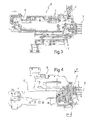
- Figure 6 is a cross-sectional view similar to that of Figure 5 representing the intermediate element in the assembly step; and
- Figures 7 and 8 are cross-sectional views of the intermediate element of Figure 2 and of the supporting body of Figure 1 during distinct steps of the method forming the subject of the invention.
Claims (10)
- A method for making a supporting body (1) for the lock of a motor vehicle, comprising the steps of:said method being characterized in that said intermediate element (8) and said conductive paths (3) are made independently, and in that said conductive paths (3) are fixed to said intermediate element (8) by constraint means (15, 16) of a mechanical type.forming an intermediate element (8) made of insulating material provided with conductive paths (3);setting said intermediate element (8) equipped with conductive paths (3) within a mould (23) for forming said supporting body (1); andinjecting fluid material into said mould (23) for carrying out co-moulding of said supporting body (1);
- The method according to Claim 1, characterized in that said intermediate element (8) is obtained by moulding and is provided with seats (11, 12) for receiving said conductive paths (3).
- The method according to Claim 1 or Claim 2, characterized in that said constraint means of a mechanical type comprise a plurality of first engagement elements (15) carried by said intermediate element (8), which can be coupled to second engagement elements (16) carried by said conductive paths (3).
- The method according to Claim 3, characterized in that said first and second engagement elements comprise pins (15) and holes (16) that are complementary to one another.
- The method according to any one of the preceding claims, characterized in that said conductive paths (3) are fixed to said intermediate element (8) according to layers (4, 5, 6) set on top of one another.
- The method according to Claim 5, characterized in that at least two (4, 5; 6) of said layers of conductive paths (3) are fixed to respective opposite faces (9, 10) of said intermediate element (8).
- The method according to Claim 5 or Claim 6, characterized in that said conductive paths (3) of each layer (4, 5, 6) are joined together by connecting portions (7) so as to form a single body, and in that said connecting portions (7) are subjected to a blanking operation subsequently to fixing of said layers (4, 5, 6) of conductive paths (3) to said intermediate element (8).
- The method according to Claim 5 or Claim 6, characterized in that said conductive paths (3) of each layer (4, 5, 6) are joined together by connecting portions (7) so as to form a single body, and in that said connecting portions (7) are removed prior to fixing of said layers (4, 5, 6) of conductive paths (3) to said intermediate element (8).
- A supporting body (1) for the lock of a motor vehicle obtained by means of the method according to any one of the preceding claims, characterized in that it comprises a plurality of conductive paths (3) co-moulded with the supporting body (1) itself and arranged according to layers (4, 5, 6) set on top of one another.
- An intermediate element (8) made of insulating material obtained in the course of the method according to any one of Claims 1 to 8, characterized in that it carries a plurality of conductive paths (3) fixed on opposite faces (9, 10) of its own by constraint means (15, 16) of a mechanical type.
Applications Claiming Priority (2)
| Application Number | Priority Date | Filing Date | Title |
|---|---|---|---|
| ITTO20030846 | 2003-10-28 | ||
| ITTO20030846 ITTO20030846A1 (en) | 2003-10-28 | 2003-10-28 | PROCEDURE FOR THE CONSTRUCTION OF A SUPPORTING BODY FOR A LOCK OF A MOTOR VEHICLE AND SUPPORT BODY OBTAINED. |
Publications (2)
| Publication Number | Publication Date |
|---|---|
| EP1527967A1 true EP1527967A1 (en) | 2005-05-04 |
| EP1527967B1 EP1527967B1 (en) | 2007-06-27 |
Family
ID=34401328
Family Applications (1)
| Application Number | Title | Priority Date | Filing Date |
|---|---|---|---|
| EP20040105345 Expired - Lifetime EP1527967B1 (en) | 2003-10-28 | 2004-10-27 | A method for making a supporting body for the lock of a motor vehicle, and a supporting body thus obtained |
Country Status (5)
| Country | Link |
|---|---|
| US (2) | US7591969B2 (en) |
| EP (1) | EP1527967B1 (en) |
| CA (1) | CA2486669C (en) |
| DE (1) | DE602004007216T2 (en) |
| IT (1) | ITTO20030846A1 (en) |
Families Citing this family (4)
| Publication number | Priority date | Publication date | Assignee | Title |
|---|---|---|---|---|
| ITBG20050028A1 (en) * | 2005-05-13 | 2006-11-14 | Abb Service Srl | DEVICE FOR DETECTION OF THE POSITION OF A MOBILE ELEMENT WHICH IS PAIRED TO IT AND ITS MOBILE ELEMENT. |
| DE102011082140B4 (en) | 2011-09-05 | 2024-09-19 | Kiekert Aktiengesellschaft | Lock for a motor vehicle |
| DE102012010722B4 (en) | 2012-05-30 | 2025-07-24 | Kiekert Aktiengesellschaft | Motor vehicle door lock housing and method for its manufacture |
| DE102014001631A1 (en) * | 2014-02-07 | 2015-04-30 | Audi Ag | Electrical wiring between a transmission control unit and an electrical transmission component |
Citations (3)
| Publication number | Priority date | Publication date | Assignee | Title |
|---|---|---|---|---|
| US4766520A (en) * | 1986-12-05 | 1988-08-23 | Capsonic Group, Inc. | Injection molded circuit housing |
| DE19535813C1 (en) * | 1995-09-26 | 1996-09-19 | Siemens Ag | Transmitting and receiving device for motor vehicle theft protection system, esp. electronic immobiliser |
| EP1102351A1 (en) * | 1999-11-15 | 2001-05-23 | Sumitomo Wiring Systems, Ltd. | A wire laying plate assembly and a molding process for an insulation plate |
Family Cites Families (12)
| Publication number | Priority date | Publication date | Assignee | Title |
|---|---|---|---|---|
| US3678577A (en) * | 1969-09-25 | 1972-07-25 | Jerobee Ind Inc | Method of contemporaneously shearing and bonding conductive foil to a substrate |
| CH513460A (en) * | 1970-01-26 | 1971-09-30 | Holzer Patent Ag | Contact arrangement on a cam switch, in particular for use in program switching mechanisms |
| DE3612576C1 (en) * | 1986-04-15 | 1987-06-19 | Preh Elektro Feinmechanik | Electrical component with a plastic jacket and method for its production |
| IT1216135B (en) * | 1988-03-18 | 1990-02-22 | Sits Soc It Telecom Siemens | DIELECTRIC BY MEANS OF PROCESSES FOR THE EMPTYING OF METAL VACUUM, AND RELATIVE METAL HOLES IN A SUBSTRATE PRODUCT OBTAINED. |
| GB9108447D0 (en) * | 1991-04-19 | 1991-06-05 | Rockwell Automotive Body Syst | Vehicle door latches |
| JP3339300B2 (en) * | 1996-04-23 | 2002-10-28 | 矢崎総業株式会社 | Connector manufacturing method |
| JP2924898B1 (en) * | 1998-06-19 | 1999-07-26 | 住友電気工業株式会社 | Lead material |
| TW445680B (en) * | 1999-01-21 | 2001-07-11 | Shinetsu Polymer Co | Press-contact electrical interconnectors and method for producing the same |
| JP3872659B2 (en) * | 2001-05-22 | 2007-01-24 | 株式会社ユーシン | Manufacturing method of electric circuit built-in case and manufacturing mold thereof |
| JP3997852B2 (en) * | 2002-06-28 | 2007-10-24 | 住友電装株式会社 | Insert molded connector |
| JP4102624B2 (en) * | 2002-09-12 | 2008-06-18 | 株式会社大井製作所 | Bonding structure of plastic parts with insert-molded wiring boards |
| US20050121829A1 (en) * | 2003-12-03 | 2005-06-09 | Honeywell International, Inc. | Circuit insulation methods and systems for vehicle door latches |
-
2003
- 2003-10-28 IT ITTO20030846 patent/ITTO20030846A1/en unknown
-
2004
- 2004-10-27 EP EP20040105345 patent/EP1527967B1/en not_active Expired - Lifetime
- 2004-10-27 DE DE200460007216 patent/DE602004007216T2/en not_active Expired - Lifetime
- 2004-10-27 CA CA2486669A patent/CA2486669C/en not_active Expired - Fee Related
- 2004-10-28 US US10/975,868 patent/US7591969B2/en not_active Expired - Fee Related
-
2009
- 2009-08-17 US US12/583,227 patent/US8075319B2/en not_active Expired - Fee Related
Patent Citations (3)
| Publication number | Priority date | Publication date | Assignee | Title |
|---|---|---|---|---|
| US4766520A (en) * | 1986-12-05 | 1988-08-23 | Capsonic Group, Inc. | Injection molded circuit housing |
| DE19535813C1 (en) * | 1995-09-26 | 1996-09-19 | Siemens Ag | Transmitting and receiving device for motor vehicle theft protection system, esp. electronic immobiliser |
| EP1102351A1 (en) * | 1999-11-15 | 2001-05-23 | Sumitomo Wiring Systems, Ltd. | A wire laying plate assembly and a molding process for an insulation plate |
Also Published As
| Publication number | Publication date |
|---|---|
| EP1527967B1 (en) | 2007-06-27 |
| CA2486669C (en) | 2012-11-27 |
| US8075319B2 (en) | 2011-12-13 |
| DE602004007216T2 (en) | 2008-02-28 |
| DE602004007216D1 (en) | 2007-08-09 |
| CA2486669A1 (en) | 2005-04-28 |
| US20090308120A1 (en) | 2009-12-17 |
| ITTO20030846A1 (en) | 2005-04-29 |
| US7591969B2 (en) | 2009-09-22 |
| US20050086985A1 (en) | 2005-04-28 |
Similar Documents
| Publication | Publication Date | Title |
|---|---|---|
| JP5078408B2 (en) | Vehicle out-handle device | |
| US8075319B2 (en) | Method for making a supporting body for the lock of a motor vehicle, and a supporting body thus obtained | |
| CN113474528B (en) | Door lock device | |
| JP2005505710A (en) | Modular lock for automobile doors and doors with this lock | |
| TW201502348A (en) | Configurable electrical connector key for electronic door locks | |
| CN102842450A (en) | Power window switch | |
| CN107849874B (en) | Door locking device for vehicles | |
| US20070272565A1 (en) | Casing for an electronic key | |
| EP3950392B1 (en) | Door lock device for vehicle and method of manufacturing door lock device for vehicle | |
| KR102005605B1 (en) | Motor vehicle component support and method for the production thereof | |
| CN106413305A (en) | Housing assembly of a power operated device and method of manufacturing thereof | |
| KR101756294B1 (en) | Card type smart key and method of manufacturing thereof | |
| JP3424957B2 (en) | Method for manufacturing housing of electric door lock operating device | |
| JP2016194197A (en) | Door lock device and method of manufacturing door lock device | |
| CN105308707B (en) | Switch, method for manufacturing a switch and electronic module system | |
| JP3872659B2 (en) | Manufacturing method of electric circuit built-in case and manufacturing mold thereof | |
| CN201319467Y (en) | Assembling auxiliary tool | |
| JP2015101833A (en) | Door handle device | |
| JP2004319337A (en) | Secondary molded products for switches | |
| JP5514645B2 (en) | Locking device for vehicle opening / closing body | |
| KR200429781Y1 (en) | Seat switch structure | |
| KR101344440B1 (en) | Method for producting card type smart key using vehicle | |
| KR20250027726A (en) | Automotive lock assembly and method for manufacturing the same | |
| JP6836169B2 (en) | Vehicle door lock device | |
| KR20080015996A (en) | Seat switch structure |
Legal Events
| Date | Code | Title | Description |
|---|---|---|---|
| PUAI | Public reference made under article 153(3) epc to a published international application that has entered the european phase |
Free format text: ORIGINAL CODE: 0009012 |
|
| AK | Designated contracting states |
Kind code of ref document: A1 Designated state(s): AT BE BG CH CY CZ DE DK EE ES FI FR GB GR HU IE IT LI LU MC NL PL PT RO SE SI SK TR |
|
| AX | Request for extension of the european patent |
Extension state: AL HR LT LV MK |
|
| 17P | Request for examination filed |
Effective date: 20051102 |
|
| AKX | Designation fees paid |
Designated state(s): DE FR IT |
|
| GRAP | Despatch of communication of intention to grant a patent |
Free format text: ORIGINAL CODE: EPIDOSNIGR1 |
|
| GRAS | Grant fee paid |
Free format text: ORIGINAL CODE: EPIDOSNIGR3 |
|
| GRAA | (expected) grant |
Free format text: ORIGINAL CODE: 0009210 |
|
| RAP1 | Party data changed (applicant data changed or rights of an application transferred) |
Owner name: INTIER AUTOMOTIVE CLOSURES S.P.A. |
|
| AK | Designated contracting states |
Kind code of ref document: B1 Designated state(s): DE FR IT |
|
| REF | Corresponds to: |
Ref document number: 602004007216 Country of ref document: DE Date of ref document: 20070809 Kind code of ref document: P |
|
| ET | Fr: translation filed | ||
| PLBE | No opposition filed within time limit |
Free format text: ORIGINAL CODE: 0009261 |
|
| STAA | Information on the status of an ep patent application or granted ep patent |
Free format text: STATUS: NO OPPOSITION FILED WITHIN TIME LIMIT |
|
| 26N | No opposition filed |
Effective date: 20080328 |
|
| REG | Reference to a national code |
Ref country code: FR Ref legal event code: PLFP Year of fee payment: 13 |
|
| REG | Reference to a national code |
Ref country code: FR Ref legal event code: PLFP Year of fee payment: 14 |
|
| REG | Reference to a national code |
Ref country code: FR Ref legal event code: PLFP Year of fee payment: 15 |
|
| PGFP | Annual fee paid to national office [announced via postgrant information from national office to epo] |
Ref country code: FR Payment date: 20180913 Year of fee payment: 15 |
|
| PGFP | Annual fee paid to national office [announced via postgrant information from national office to epo] |
Ref country code: IT Payment date: 20181018 Year of fee payment: 15 |
|
| PG25 | Lapsed in a contracting state [announced via postgrant information from national office to epo] |
Ref country code: IT Free format text: LAPSE BECAUSE OF NON-PAYMENT OF DUE FEES Effective date: 20191027 |
|
| PG25 | Lapsed in a contracting state [announced via postgrant information from national office to epo] |
Ref country code: FR Free format text: LAPSE BECAUSE OF NON-PAYMENT OF DUE FEES Effective date: 20191031 |
|
| PGFP | Annual fee paid to national office [announced via postgrant information from national office to epo] |
Ref country code: DE Payment date: 20210914 Year of fee payment: 18 |
|
| REG | Reference to a national code |
Ref country code: DE Ref legal event code: R119 Ref document number: 602004007216 Country of ref document: DE |
|
| PG25 | Lapsed in a contracting state [announced via postgrant information from national office to epo] |
Ref country code: DE Free format text: LAPSE BECAUSE OF NON-PAYMENT OF DUE FEES Effective date: 20230503 |
|
| P01 | Opt-out of the competence of the unified patent court (upc) registered |
Free format text: CASE NUMBER: UPC_APP_414732/2023 Effective date: 20230525 |