EP1527913A2 - Air conditioning apparatus for rear seat arrangement - Google Patents
Air conditioning apparatus for rear seat arrangement Download PDFInfo
- Publication number
- EP1527913A2 EP1527913A2 EP04024182A EP04024182A EP1527913A2 EP 1527913 A2 EP1527913 A2 EP 1527913A2 EP 04024182 A EP04024182 A EP 04024182A EP 04024182 A EP04024182 A EP 04024182A EP 1527913 A2 EP1527913 A2 EP 1527913A2
- Authority
- EP
- European Patent Office
- Prior art keywords
- duct
- seat
- air conditioning
- ducting
- air
- Prior art date
- Legal status (The legal status is an assumption and is not a legal conclusion. Google has not performed a legal analysis and makes no representation as to the accuracy of the status listed.)
- Withdrawn
Links
Images



Classifications
-
- B—PERFORMING OPERATIONS; TRANSPORTING
- B60—VEHICLES IN GENERAL
- B60H—ARRANGEMENTS OF HEATING, COOLING, VENTILATING OR OTHER AIR-TREATING DEVICES SPECIALLY ADAPTED FOR PASSENGER OR GOODS SPACES OF VEHICLES
- B60H1/00—Heating, cooling or ventilating devices
- B60H1/00507—Details, e.g. mounting arrangements, desaeration devices
- B60H1/00514—Details of air conditioning housings
- B60H1/0055—Details of air conditioning housings the housing or parts thereof being integrated in other devices, e.g. dashboard
-
- B—PERFORMING OPERATIONS; TRANSPORTING
- B60—VEHICLES IN GENERAL
- B60H—ARRANGEMENTS OF HEATING, COOLING, VENTILATING OR OTHER AIR-TREATING DEVICES SPECIALLY ADAPTED FOR PASSENGER OR GOODS SPACES OF VEHICLES
- B60H1/00—Heating, cooling or ventilating devices
- B60H1/24—Ventilating devices where the heating or cooling is irrelevant
- B60H1/247—Disposition of several air-diffusers in a vehicle for ventilation-air circulation in a vehicle cabin
-
- B—PERFORMING OPERATIONS; TRANSPORTING
- B60—VEHICLES IN GENERAL
- B60N—SEATS SPECIALLY ADAPTED FOR VEHICLES; VEHICLE PASSENGER ACCOMMODATION NOT OTHERWISE PROVIDED FOR
- B60N2/00—Seats specially adapted for vehicles; Arrangement or mounting of seats in vehicles
- B60N2/56—Heating or ventilating devices
- B60N2/5607—Heating or ventilating devices characterised by convection
- B60N2/5621—Heating or ventilating devices characterised by convection by air
- B60N2/5628—Heating or ventilating devices characterised by convection by air coming from the vehicle ventilation system, e.g. air-conditioning system
Definitions
- the present invention relates to an arrangement of an air conditioning apparatus for a rear seat arrangement(s), especially suitable for a vehicle air conditioning for an arrangement(s) of second row and/or third row of the vehicle.
- An air conditioning apparatus for a rear seat has been proposed.
- an air conditioning apparatus for a rear seated passenger is provided at a front seat as shown in JP-A-11-192289, or is attached to a backside face of a back-support member of the front seat as shown in USP 4,840,115.
- These proposed air conditioning apparatus do not have enough flexibility with respect to the movement of the front seat.
- This invention is to provide an air conditioning apparatus for a rear seat(s) having enough flexibility of a duct with respect to the movement of a front seat.
- the air conditioning apparatus has an air conditioning unit conditioning the air to be supplied to a passenger compartment, a flexible duct connected to the air conditioning unit and arranged close to a seat portion of a front seat, and an air blow-out port connected to the flexible duct and provided in a back-support portion of the front seat so that the air is blown from the blow-out port toward a rear-seated passenger.
- the flexible duct may be U-shaped so that a bottom thereof is oriented toward a front side of a vehicle.
- the vehicle has a second-row seat and a third-row seat.
- the second or third row seat may be fully folded up or removed from a floor of the vehicle.
- a connection duct such as a floor duct may be provided and a ducting to which the blow-out port is attached is connected to the connection duct by a fit-connecting member such as a rubber grommet, so that the ducting is detached from the connection duct when the seat containing the ducting is fully folded up or removed from the floor.
- FIG. 1 is a schematic cross sectional view of an air conditioning apparatus for a rear seat at an original position in the first embodiment of the present invention
- FIG. 2 is a schematic cross sectional view of an air conditioning apparatus for a rear seat at a moved position in the first embodiment of the present invention
- FIG.3 is a schematic cross sectional view of an air conditioning apparatus for a rear seat at a down position and a tilted (raised) position in a second embodiment of the present invention
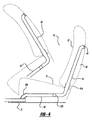
- FIG.4 is a schematic cross sectional view of an air conditioning apparatus for a rear seat at a down position and a tilted (raised) position in a third embodiment of the present invention
- FIG.5 is a schematic cross sectional view of an air conditioning apparatus for a rear seat at a removed position in a modified embodiment of the second embodiment in the present invention
- FIG.6 is a schematic cross sectional view of an air conditioning apparatus for a rear seat at a down position in the modified embodiment of the second embodiment in the present invention.
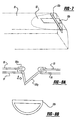
- FIG. 7 is an enlarged perspective view showing an end portion of a floor duct in the modified embodiment of the second embodiment in the present invention.
- FIG. 8A is an enlarged cross sectional view showing an opening protrusion as an air tight connection in the modified embodiment of the second embodiment in the present invention.
- FIG. 8B is an enlarged and partial front view showing the opening protrusion from a direction of the arrow A in FIG. 8A in the modified embodiment of the second embodiment in the present invention.
- an air conditioning apparatus of the present invention may especially be adapted to a front seat, or a first-row seat of a vehicle in this embodiment. It could be adapted to a second-row seat of a vehicle such as a mini van.
- a front seat means, in this invention, a seat which is arranged in front of a rear-side seat such as a rear seat in a sedan, a second row seat or a third row seat in a minivan.
- a front seat 10 is shown with a broken line.
- the front seat 10 has a seat portion 11 and a back-support portion 12. These portions are basically the same as those of a normal seat currently provided in a conventional vehicle. These portions are usually filled with foam or cushion material.
- the back-support portion 12 is pivotally connected to the seat portion 11 (not shown), so that it can be leaned in a back or forward direction, or folded down on the seat portion 11.
- the seat portion 11 can travel in a back and forward direction along a seat slide mechanism (not shown) and in a height direction so as to be adjusted in a position at which a driver or passenger desires.
- a ducting in the front seat 10 will be described in detail later.
- an air conditioning unit is conventionally installed inside an instrumental panel (both of them are not shown).
- the air conditioning unit conventionally has a normal configuration, that is, it has an unit case, a blower unit attached to the case to cause the flow of air, an evaporator, a heater unit, an air-mixing door, some ducts, blow-out ports and the like.
- One of the ducts extends to a center console of the vehicle (not shown), and is connected to a center duct 21 (partially shown) for the air conditioning apparatus for a rear seat.
- the center duct 21 is branched out to go under the seat 10 to a connector 21 a.
- a flexible duct member 22 of a flexible duct 20 (a rear-side seat duct) is connected to the connector 21 a.
- the flexible duct member 22 may be a bellows member.
- the flexible duct member 22 is arranged in a cavity or recess (not shown) formed in the foam of the seat portion 11. The cavity in the seat portion allows the flexible duct member 22 to move therein.
- the flexible duct 22 has a U-shape in which a bottom of the U-shape is oriented to a front side of the vehicle.
- the flexible duct 22 is connected to a leading duct member 23 through a connector 22a.
- the leading duct member 23 is supported by the foam inside the back-support portion 12.
- the leading duct member 23 has, in this embodiment, a flexible portion 23a located at a boundary between the seat portion 11 and the back-support portion 12, so as to be able to bend when the back-support portion 12 is folded in the forward or back direction, or the leading duct member 23 may be entirely flexible.
- the leading duct member 23 is connected to a blow-out port 24 provided at a back surface of the back-support portion 12.
- the air conditioned in the air conditioning unit is led to the port 24 through the flexible duct 20.
- the port 24 is located at a position suitable for the correct position to direct air to the occupant's body and face.
- the port 24 has a grill for controlling the flow and the direction of the conditioned air. Also, the port 24 has the capability to be closed.
- the rear-side seat duct 20 moves with the travel of the seat 10.
- the flexible duct member 22 allows the rear-side seat duct 20 to move in conjunction with the travel of the seat 10 by transforming its U-shape in any direction.
- the flexible duct member 22 changes its configuration such that the two sides of the U-shape are further away from one another, in this embodiment.
- the rear-side seat duct 20 can be made by a blow mold process or an injection mold process.
- the connectors 21a, 22a are provided to connect the duct members, the rear-side seat duct 20 can be made as a single duct member without connectors in a forming process such as the injection molding.
- the U-shape of the flexible duct member 22 is disposed such that a U-character of the shape faces a plane defined by a traveling direction of the vehicle and a vertical direction of the vehicle, it can be disposed such that the U-character of the shape faces a plane defined by the traveling direction of the vehicle and a horizontal direction of the vehicle so that the U-shaped flexible duct member 22 looks like a ring on the floor of the vehicle.
- the rear seat duct 20 is adapted to the first-row seat, it can be adapted any seat in a vehicle.
- center duct 21 can be a floor duct which is covered with a mat or the like as is disclosed in embodiments below.
- a seat 10 may, or may not slide with respect to a floor of a vehicle such as a second-row seat in a minivan.
- This seat can be fully folded up. That is, a back-support portion can be folded down so as to contact a seat portion 11. Further, the seat portion can pivotally rotate with respect to a certain point as shown in Fig. 3.
- a dashed line for the seat 10 shows a folded state of the seat portion 11, but does not show the final folded position.
- the seat portion of a second-row or third-row seat in a minivan can pivotally rotate with respect to the floor of the vehicle to be folded up.
- a rear-side seat duct 30 has a leading duct member 32 that can be removable from a floor duct 31 when the seat portion 11 of the seat 10 is pivotally rotated so as to be apart from the floor of the vehicle.
- a rubber grommet 32 is attached to the leading duct member 33 to achieve the air-tight connection between the floor duct 31 and the leading duct member 33 when the grommet 32 contacts the floor duct 31.
- the leading duct 33 also has a flexible portion 33a to allow it to bend when the back-support portion 12 is reclined.
- An outlet of the leading duct 33 is connected to a blow-out port 34.
- the seat 10 also can be removable from the floor.
- a floor duct 31 can have a fixed floor duct member 31 a and a slidable duct member 31 b slidably connected to the fixed floor duct member 31 a.
- the floor duct 31 allows the seat 10 to slide to the front side or the rear side of the vehicle.
- a seat 10 can be folded up so that a seat portion thereof is spaced from a floor of a vehicle.
- a rear-side seat duct 40 has a flexible duct member 42 which is connected to a floor duct 41 at a position close to a rotatable point of the seat member 11 through a flexible member 42a.
- the rear-side seat duct 40 also has a leading duct member 43.
- the leading duct member 43 has a flexible portion 43a, it is connected to the flexible duct member 42 through a connector 42b, and it is connected to a blow-out port 44.
- the flexible member 42a may be a bellows member.
- the flexible member 42a allows the rear-side seat duct 40 to travel in conjunction with the movement of the seat 10.
- the rear-side seat duct 40 is not necessarily removable from the floor duct 41. If the seat 10 can be removed from the floor of the vehicle, an air-tight connection like the one shown in Fig. 3 may be attached to the flexible member 42a, or a tip portion of the flexible member 42a has an air-tight connection configuration.
- a modified embodiment of the second embodiment in the present invention will be described with reference to Figs. 5 to 8B.
- the floor duct is left open at an end portion thereof. In this situation, extraneous substance such as dust, sand, mud or water can enter into the duct.
- a floor duct 51 has a door 52.
- the door 52 is capable of closing an opening of the floor duct 51 for communication between the floor duct and a leading duct 53 of a rear-side seat duct 50 when the seat portion 11 of the seat 10 is folded up to prevent the extraneous substance from getting into the floor duct 51 as shown in Fig. 5. Also, the door 52 is opened when the seat 10 is in a down position as shown in Fig. 6. The door 52 is pivotally rotatable with respect to a shaft 52a, and is forced to close the opening by a spring member 52b to push the door 52 toward a closing position. In Fig. 6, the floor duct is partially cut out to show how the door 52 and an opening protrusion 53b of the leading duct work together.
- the spring member 52b is made of a plate metal having a L-shape, which is attached to a wall of the floor duct 51 in this embodiment as shown in Fig. 7.
- the spring member 52b can be some other type of spring such as a coil spring.
- an opening protrusion 53b is attached to an opening provided at a bottom of the leading duct 53.
- the opening protrusion 53b is a rubber grommet having stiffness enough to open the door 52 when the seat portion 11 of the seat is at a down position. The stiffness can be gained by increasing its thickness.
- the opening protrusion 53b achieves an air-tight connection between the floor duct 51 and the leading duct member 53 in Fig. 8 in which a cross section of the opening protrusion 53b is shown with a part of the floor duct 51 and the leading duct member 53. As shown in Fig. 8A, the opening protrusion 53b is attached to the leading duct member 53 with its connecting end 53b 1 .
- the air sent from the air conditioning unit and passing through the floor duct 51 passes an opening (shown in Fig. 8B) provided in a protrusion 53b 2 along a direction shown as an arrow A, and goes up into the leading duct 53 toward a blow-out port (not shown).
- the opening protrusion 53b also serves as an air tight connection as shown in Fig. 8A.
- the door 52 prevents the extraneous substance from coming into the floor duct 51 even when the leading duct member 53 is detached from the floor duct 51 in conjunction with the seat 10 being folded up or removed from the floor.
- the detachable feature described in the second, third or modified embodiment can be adapted to the duct member described in the first embodiment, as so these are to have flexibility in ducting structure as an air conditioning apparatus for a rear-side seated passenger which can be adapted to various types of seat structure.
- the door 52 is provided to close the opening formed in the floor duct 51, instead of using the door 52, a rid member can be placed on the opening formed in the floor duct 51 to prevent the extraneous substance from getting into the floor duct 51.
Landscapes
- Engineering & Computer Science (AREA)
- Mechanical Engineering (AREA)
- Physics & Mathematics (AREA)
- Thermal Sciences (AREA)
- Aviation & Aerospace Engineering (AREA)
- Transportation (AREA)
- Air-Conditioning For Vehicles (AREA)
- Chair Legs, Seat Parts, And Backrests (AREA)
Abstract
Description
- The present invention relates to an arrangement of an air conditioning apparatus for a rear seat arrangement(s), especially suitable for a vehicle air conditioning for an arrangement(s) of second row and/or third row of the vehicle.
- An air conditioning apparatus for a rear seat has been proposed. For example, an air conditioning apparatus for a rear seated passenger is provided at a front seat as shown in JP-A-11-192289, or is attached to a backside face of a back-support member of the front seat as shown in USP 4,840,115. These proposed air conditioning apparatus do not have enough flexibility with respect to the movement of the front seat.
- This invention is to provide an air conditioning apparatus for a rear seat(s) having enough flexibility of a duct with respect to the movement of a front seat.
- According to a first aspect of the invention, the air conditioning apparatus has an air conditioning unit conditioning the air to be supplied to a passenger compartment, a flexible duct connected to the air conditioning unit and arranged close to a seat portion of a front seat, and an air blow-out port connected to the flexible duct and provided in a back-support portion of the front seat so that the air is blown from the blow-out port toward a rear-seated passenger.
- The flexible duct may be U-shaped so that a bottom thereof is oriented toward a front side of a vehicle.
- Especially, in a minivan-type vehicle, the vehicle has a second-row seat and a third-row seat. The second or third row seat may be fully folded up or removed from a floor of the vehicle. In this case, a connection duct such as a floor duct may be provided and a ducting to which the blow-out port is attached is connected to the connection duct by a fit-connecting member such as a rubber grommet, so that the ducting is detached from the connection duct when the seat containing the ducting is fully folded up or removed from the floor.
- Further areas of applicability of the present invention will become apparent from the detailed description provided hereinafter. It should be understood that the detailed description and specific examples, while indicating the preferred embodiment of the invention, are intended for purposes of illustration only and are not intended to limit the scope of the invention.
- The present invention will become more fully understood from the detailed description and the accompanying drawings, wherein:
- FIG. 1 is a schematic cross sectional view of an air conditioning apparatus for a rear seat at an original position in the first embodiment of the present invention;
- FIG. 2 is a schematic cross sectional view of an air conditioning apparatus for a rear seat at a moved position in the first embodiment of the present invention;
- FIG.3 is a schematic cross sectional view of an air conditioning apparatus for a rear seat at a down position and a tilted (raised) position in a second embodiment of the present invention;
- FIG.4 is a schematic cross sectional view of an air conditioning apparatus for a rear seat at a down position and a tilted (raised) position in a third embodiment of the present invention;
- FIG.5 is a schematic cross sectional view of an air conditioning apparatus for a rear seat at a removed position in a modified embodiment of the second embodiment in the present invention;
- FIG.6 is a schematic cross sectional view of an air conditioning apparatus for a rear seat at a down position in the modified embodiment of the second embodiment in the present invention;
- FIG. 7 is an enlarged perspective view showing an end portion of a floor duct in the modified embodiment of the second embodiment in the present invention;
- FIG. 8A is an enlarged cross sectional view showing an opening protrusion as an air tight connection in the modified embodiment of the second embodiment in the present invention; and
- FIG. 8B is an enlarged and partial front view showing the opening protrusion from a direction of the arrow A in FIG. 8A in the modified embodiment of the second embodiment in the present invention.
- The following description of the preferred embodiment(s) is merely exemplary in nature and is in no way intended to limit the invention, its application, or uses. Specific embodiments of the present invention will now be described hereinafter with reference to the accompanying drawings in which the same or similar component parts are designated by the same or similar reference numerals.
- First, an air conditioning apparatus of the present invention may especially be adapted to a front seat, or a first-row seat of a vehicle in this embodiment. It could be adapted to a second-row seat of a vehicle such as a mini van. Namely, a front seat means, in this invention, a seat which is arranged in front of a rear-side seat such as a rear seat in a sedan, a second row seat or a third row seat in a minivan.
- In Fig. 1, a
front seat 10 is shown with a broken line. Thefront seat 10 has aseat portion 11 and a back-support portion 12. These portions are basically the same as those of a normal seat currently provided in a conventional vehicle. These portions are usually filled with foam or cushion material. - The back-
support portion 12 is pivotally connected to the seat portion 11 (not shown), so that it can be leaned in a back or forward direction, or folded down on theseat portion 11. Theseat portion 11 can travel in a back and forward direction along a seat slide mechanism (not shown) and in a height direction so as to be adjusted in a position at which a driver or passenger desires. A ducting in thefront seat 10 will be described in detail later. - In this embodiment, an air conditioning unit is conventionally installed inside an instrumental panel (both of them are not shown). The air conditioning unit conventionally has a normal configuration, that is, it has an unit case, a blower unit attached to the case to cause the flow of air, an evaporator, a heater unit, an air-mixing door, some ducts, blow-out ports and the like. One of the ducts extends to a center console of the vehicle (not shown), and is connected to a center duct 21 (partially shown) for the air conditioning apparatus for a rear seat.
- The
center duct 21 is branched out to go under theseat 10 to aconnector 21 a. Aflexible duct member 22 of a flexible duct 20 (a rear-side seat duct) is connected to theconnector 21 a. In this embodiment, theflexible duct member 22 may be a bellows member. Theflexible duct member 22 is arranged in a cavity or recess (not shown) formed in the foam of theseat portion 11. The cavity in the seat portion allows theflexible duct member 22 to move therein. Theflexible duct 22 has a U-shape in which a bottom of the U-shape is oriented to a front side of the vehicle. Theflexible duct 22 is connected to a leadingduct member 23 through aconnector 22a. The leadingduct member 23 is supported by the foam inside the back-support portion 12. The leadingduct member 23 has, in this embodiment, aflexible portion 23a located at a boundary between theseat portion 11 and the back-support portion 12, so as to be able to bend when the back-support portion 12 is folded in the forward or back direction, or the leadingduct member 23 may be entirely flexible. The leadingduct member 23 is connected to a blow-outport 24 provided at a back surface of the back-support portion 12. The air conditioned in the air conditioning unit is led to theport 24 through theflexible duct 20. Theport 24 is located at a position suitable for the correct position to direct air to the occupant's body and face. Theport 24 has a grill for controlling the flow and the direction of the conditioned air. Also, theport 24 has the capability to be closed. - As shown in Fig. 2, the rear-
side seat duct 20 moves with the travel of theseat 10. Especially, theflexible duct member 22 allows the rear-side seat duct 20 to move in conjunction with the travel of theseat 10 by transforming its U-shape in any direction. When theseat portion 11 is raised to a higher position, theflexible duct member 22 changes its configuration such that the two sides of the U-shape are further away from one another, in this embodiment. - The rear-
side seat duct 20 can be made by a blow mold process or an injection mold process. In this embodiment, although theconnectors side seat duct 20 can be made as a single duct member without connectors in a forming process such as the injection molding. - Although the U-shape of the
flexible duct member 22 is disposed such that a U-character of the shape faces a plane defined by a traveling direction of the vehicle and a vertical direction of the vehicle, it can be disposed such that the U-character of the shape faces a plane defined by the traveling direction of the vehicle and a horizontal direction of the vehicle so that the U-shapedflexible duct member 22 looks like a ring on the floor of the vehicle. - In the first embodiment described above, although the
rear seat duct 20 is adapted to the first-row seat, it can be adapted any seat in a vehicle. - Moreover, the
center duct 21 can be a floor duct which is covered with a mat or the like as is disclosed in embodiments below. - Next, a second embodiment will be described with reference to Figs. 3 and 4. In this embodiment, a
seat 10 may, or may not slide with respect to a floor of a vehicle such as a second-row seat in a minivan. This seat can be fully folded up. That is, a back-support portion can be folded down so as to contact aseat portion 11. Further, the seat portion can pivotally rotate with respect to a certain point as shown in Fig. 3. A dashed line for theseat 10 shows a folded state of theseat portion 11, but does not show the final folded position. Ordinarily, the seat portion of a second-row or third-row seat in a minivan can pivotally rotate with respect to the floor of the vehicle to be folded up. Therefore, in this embodiment, a rear-side seat duct 30 has a leadingduct member 32 that can be removable from afloor duct 31 when theseat portion 11 of theseat 10 is pivotally rotated so as to be apart from the floor of the vehicle. Arubber grommet 32 is attached to the leadingduct member 33 to achieve the air-tight connection between thefloor duct 31 and the leadingduct member 33 when thegrommet 32 contacts thefloor duct 31. The leadingduct 33 also has aflexible portion 33a to allow it to bend when the back-support portion 12 is reclined. An outlet of the leadingduct 33 is connected to a blow-outport 34. In this embodiment, theseat 10 also can be removable from the floor. - Moreover, in this embodiment, a
floor duct 31 can have a fixedfloor duct member 31 a and aslidable duct member 31 b slidably connected to the fixedfloor duct member 31 a. In this case, thefloor duct 31 allows theseat 10 to slide to the front side or the rear side of the vehicle. - A third embodiment of the present invention Will be described with reference to Fig. 4. Like the second embodiment, a
seat 10 can be folded up so that a seat portion thereof is spaced from a floor of a vehicle. In this embodiment, a rear-side seat duct 40 has aflexible duct member 42 which is connected to a floor duct 41 at a position close to a rotatable point of theseat member 11 through aflexible member 42a. The rear-side seat duct 40 also has a leadingduct member 43. The leadingduct member 43 has aflexible portion 43a, it is connected to theflexible duct member 42 through aconnector 42b, and it is connected to a blow-outport 44. - The
flexible member 42a may be a bellows member. Theflexible member 42a allows the rear-side seat duct 40 to travel in conjunction with the movement of theseat 10. In this embodiment, the rear-side seat duct 40 is not necessarily removable from the floor duct 41. If theseat 10 can be removed from the floor of the vehicle, an air-tight connection like the one shown in Fig. 3 may be attached to theflexible member 42a, or a tip portion of theflexible member 42a has an air-tight connection configuration. - A modified embodiment of the second embodiment in the present invention will be described with reference to Figs. 5 to 8B. In the second embodiment, when the
seat 10 is removed from the floor of the vehicle or is pivotally rotated or folded up so as to be spaced from the floor of the vehicle to make more cargo space in the vehicle, the floor duct is left open at an end portion thereof. In this situation, extraneous substance such as dust, sand, mud or water can enter into the duct. In this embodiment, afloor duct 51 has adoor 52. - The
door 52 is capable of closing an opening of thefloor duct 51 for communication between the floor duct and a leadingduct 53 of a rear-side seat duct 50 when theseat portion 11 of theseat 10 is folded up to prevent the extraneous substance from getting into thefloor duct 51 as shown in Fig. 5. Also, thedoor 52 is opened when theseat 10 is in a down position as shown in Fig. 6. Thedoor 52 is pivotally rotatable with respect to ashaft 52a, and is forced to close the opening by aspring member 52b to push thedoor 52 toward a closing position. In Fig. 6, the floor duct is partially cut out to show how thedoor 52 and anopening protrusion 53b of the leading duct work together. - The
spring member 52b is made of a plate metal having a L-shape, which is attached to a wall of thefloor duct 51 in this embodiment as shown in Fig. 7. Thespring member 52b can be some other type of spring such as a coil spring. - On the other hand, an
opening protrusion 53b is attached to an opening provided at a bottom of the leadingduct 53. Theopening protrusion 53b is a rubber grommet having stiffness enough to open thedoor 52 when theseat portion 11 of the seat is at a down position. The stiffness can be gained by increasing its thickness. Theopening protrusion 53b achieves an air-tight connection between thefloor duct 51 and the leadingduct member 53 in Fig. 8 in which a cross section of theopening protrusion 53b is shown with a part of thefloor duct 51 and the leadingduct member 53. As shown in Fig. 8A, theopening protrusion 53b is attached to the leadingduct member 53 with its connectingend 53b1. The air sent from the air conditioning unit and passing through thefloor duct 51 passes an opening (shown in Fig. 8B) provided in aprotrusion 53b2 along a direction shown as an arrow A, and goes up into the leadingduct 53 toward a blow-out port (not shown). Theopening protrusion 53b also serves as an air tight connection as shown in Fig. 8A. - In this embodiment, the
door 52 prevents the extraneous substance from coming into thefloor duct 51 even when the leadingduct member 53 is detached from thefloor duct 51 in conjunction with theseat 10 being folded up or removed from the floor. - The description of the invention is merely exemplary in nature and, thus, variations that do not depart from the gist of the invention are intended to be within the scope of the invention. Such variations are not to be regarded as a departure from the spirit and scope of the invention.
- For example, the detachable feature described in the second, third or modified embodiment can be adapted to the duct member described in the first embodiment, as so these are to have flexibility in ducting structure as an air conditioning apparatus for a rear-side seated passenger which can be adapted to various types of seat structure.
- In the modified embodiment, although the
door 52 is provided to close the opening formed in thefloor duct 51, instead of using thedoor 52, a rid member can be placed on the opening formed in thefloor duct 51 to prevent the extraneous substance from getting into thefloor duct 51.
Claims (9)
- An air conditioning apparatus for a rear seat comprising:an air conditioning unit capable of supplying the conditioned air to a cabin of a vehicle;a ducting provided at a front seat in the vehicle having a flexible duct member with a U-shape to allow said ducting to travel in conjunction with the travel of the front seat; anda blow-out port from which the conditioned air, which is sent from the air conditioning unit, is blown out toward a passenger being seated on the rear seat, said blow-out port provided in an appropriate position at a back surface of said front seat to supply the conditioned air to said passenger, and said blow-out port connected to said ducting in the front seat.
- An air conditioning apparatus according to claim 1, further comprising a connection duct connecting the air conditioning unit and the ducting.
- An air conditioning apparatus according to claim 2, wherein said connection duct is a center duct located in a center console of the vehicle.
- An air conditioning apparatus according to claim 2, wherein said connection duct is a floor duct located on a floor inside the vehicle.
- An air conditioning apparatus according to claim 2, further comprising an air tight connection provided between the ducting and the connection duct so that the ducting can be spaced from the connection duct when the front seat is folded up or removed from a floor of the vehicle.
- An air conditioning apparatus according to claim 1, wherein said ducting further comprises:wherein said flexible duct is provided in a cavity formed in a seat portion of the front seat.a leading duct member provided in a back-support portion of the front seat, having two ends, wherein one of the two ends is connected to said flexible duct member, and other one of the two ends is connected to the blow-out port,
- An air conditioning apparatus according to claim 1, wherein said ducting is formed as a single member by a molding process.
- An air conditioning apparatus for a rear seat comprising:an air conditioning unit capable of supplying the conditioned air to a cabin of a vehicle;a connection duct leading the conditioned air to a rear side of the vehicle;a ducting provided at a front seat in the vehicle having a duct member and a blow-out port from which the conditioned air, which has passed through the connection duct, is blown out toward a passenger being seated on the rear seat; andan air tight connecting member provided between said connection duct and said ducting, said air tight connecting member providing air-tight connection therebetween, further said air tight connecting member capable of allowing said ducting to be detached from said connection duct in conjunction with a folded up condition of said front seat or a removed condition of said front seat.
- An air conditioning apparatus according to claim 8, further comprising:a door provided at the connection duct to close an opening formed in the connection duct for communicating with the ducting when the ducting is detached from the connection duct; andan opening protrusion provided at the air tight connecting member, said opening protrusion having an opening to communicate with the connection duct, and said opening protrusion opening said door so that the air tight connecting member fits with the opening formed in the connection duct when the front seat is in a down position, so that the conditioned air go through the opening formed in the opening protrusion.
Applications Claiming Priority (2)
| Application Number | Priority Date | Filing Date | Title |
|---|---|---|---|
| US694253 | 1985-01-24 | ||
| US10/694,253 US20050087325A1 (en) | 2003-10-27 | 2003-10-27 | Air conditioning apparatus for rear seat arrangement |
Publications (2)
| Publication Number | Publication Date |
|---|---|
| EP1527913A2 true EP1527913A2 (en) | 2005-05-04 |
| EP1527913A3 EP1527913A3 (en) | 2006-03-22 |
Family
ID=34423335
Family Applications (1)
| Application Number | Title | Priority Date | Filing Date |
|---|---|---|---|
| EP04024182A Withdrawn EP1527913A3 (en) | 2003-10-27 | 2004-10-11 | Air conditioning apparatus for rear seat arrangement |
Country Status (3)
| Country | Link |
|---|---|
| US (1) | US20050087325A1 (en) |
| EP (1) | EP1527913A3 (en) |
| JP (1) | JP2005126063A (en) |
Cited By (9)
| Publication number | Priority date | Publication date | Assignee | Title |
|---|---|---|---|---|
| WO2008062295A1 (en) * | 2006-11-24 | 2008-05-29 | Toyota Jidosha Kabushiki Kaisha | Vehicle seat structure |
| DE102007042055A1 (en) | 2007-09-05 | 2009-03-12 | Behr Gmbh & Co. Kg | Connecting device for use in vehicle e.g. van, to connect air ducts in seat and center console, has connection channel comprising area that provides translational movement of adjacent and sealed areas relative to each other |
| DE102008037070A1 (en) * | 2008-08-08 | 2010-02-11 | Bayerische Motoren Werke Aktiengesellschaft | Center console for a motor vehicle |
| CN105015301A (en) * | 2014-01-13 | 2015-11-04 | 通用汽车环球科技运作有限责任公司 | Systems for improving climate comfort for rear vehicle passengers |
| US9738155B2 (en) | 2014-10-14 | 2017-08-22 | Ford Global Technologies, Llc | Shifter-supporting base and shifter assembly and vehicle employing the same |
| DE102009022847B4 (en) | 2008-06-23 | 2018-04-26 | MAN Truck & Bus Österreich AG | Motor vehicle with internal air distribution for heating and / or air conditioning system |
| US10023084B2 (en) | 2015-07-15 | 2018-07-17 | Gentherm Inc. | Vehicle seat with slidable air coupling |
| DE102017121423A1 (en) * | 2017-09-15 | 2019-03-21 | Volkswagen Aktiengesellschaft | Ventilation device for a vehicle |
| US12083854B2 (en) | 2019-04-08 | 2024-09-10 | Audi Ag | Air-conditioning arrangement for a vehicle, and vehicle |
Families Citing this family (12)
| Publication number | Priority date | Publication date | Assignee | Title |
|---|---|---|---|---|
| FR2874552B1 (en) * | 2004-08-27 | 2006-10-06 | Valeo Climatisation Sa | DEVICE FOR JOINING AN AERATION DUCT EQUIPPING THE SEAT OF A TILTING AND / OR REMOVABLE SEAT, IN PARTICULAR A VEHICLE, AND A CONDUIT OF AIR SUPPLY. |
| DE102006016091B4 (en) * | 2006-04-04 | 2009-10-01 | Johnson Controls Gmbh | Vehicle seat with an air outlet opening on the back of the backrest part |
| JP5381834B2 (en) * | 2010-03-17 | 2014-01-08 | 株式会社デンソー | Vehicle seat air conditioner |
| WO2013145172A1 (en) * | 2012-03-28 | 2013-10-03 | トヨタ自動車株式会社 | Vehicle air-conditioning device |
| JP5983129B2 (en) * | 2012-07-19 | 2016-08-31 | トヨタ紡織株式会社 | Vehicle seat with air conditioner |
| US9168810B2 (en) * | 2012-10-09 | 2015-10-27 | Delphi Technologies, Inc. | Heating and cooling system for occupants of the rear portion of a vehicle |
| JP6119569B2 (en) * | 2013-11-18 | 2017-04-26 | 株式会社デンソー | Vehicle seat air conditioner |
| CN109476215A (en) | 2016-07-19 | 2019-03-15 | 株式会社电装 | Air conditioner for vehicle |
| WO2018158987A1 (en) | 2017-03-01 | 2018-09-07 | テイ・エス テック株式会社 | Vehicle seat |
| DE102019204961A1 (en) * | 2019-04-08 | 2020-02-27 | Audi Ag | Ventilation device for a vehicle |
| KR20210156021A (en) * | 2020-06-17 | 2021-12-24 | 현대자동차주식회사 | Ventilation apparatus for vehicle seat |
| IT202300010572A1 (en) * | 2023-05-25 | 2024-11-25 | Ferrari Spa | SEAT FOR A MOTOR VEHICLE |
Citations (2)
| Publication number | Priority date | Publication date | Assignee | Title |
|---|---|---|---|---|
| US4840115A (en) | 1987-05-04 | 1989-06-20 | Bayerische Motoren Werke Aktiengesellschaft | Air outlet arrangement of a heating and/or air-conditioning installation, especially for the rear space of a passenger motor vehicle |
| JPH11192289A (en) | 1997-12-26 | 1999-07-21 | Miura Co Ltd | Safety mechanism for pressure vessel |
Family Cites Families (34)
| Publication number | Priority date | Publication date | Assignee | Title |
|---|---|---|---|---|
| US3127931A (en) * | 1959-05-04 | 1964-04-07 | Gen Motors Corp | Heating and cooling employing aerated car seats |
| US2989854A (en) * | 1960-03-28 | 1961-06-27 | Gen Motors Corp | Vehicle refrigeration |
| US3394887A (en) * | 1965-08-03 | 1968-07-30 | Chrysler Corp | Rear seat heater |
| US3550522A (en) * | 1969-01-29 | 1970-12-29 | Edward J Bauer | Telescopic,portable temperature control unit for the rear seat portion of an automobile |
| DE2450092A1 (en) * | 1974-10-22 | 1976-04-29 | Castelli Kg | DEVICE FOR DISTRIBUTION OF AIR CONDITIONED AIR |
| SE423211B (en) * | 1979-01-25 | 1982-04-26 | Volvo Ab | ADDITIONAL UNIT FOR AIR VEHICLES |
| JPS5677417U (en) * | 1979-11-21 | 1981-06-24 | ||
| GB2208542A (en) * | 1987-08-13 | 1989-04-05 | Jaguar Cars | Car seat outlet in air distribution system |
| IT1232900B (en) * | 1989-08-04 | 1992-03-05 | Fiat Auto Spa | SEAT FOR VEHICLES WITH AIR CONDITIONING |
| JP3301109B2 (en) * | 1991-11-14 | 2002-07-15 | 株式会社デンソー | Air conditioning system for seats |
| US5385382A (en) * | 1993-10-06 | 1995-01-31 | Ford Motor Company | Combination seat frame and ventilation apparatus |
| FR2717426B1 (en) * | 1994-03-18 | 1996-04-26 | Valeo Thermique Habitacle | Air distribution device in the passenger compartment of a motor vehicle. |
| US5626386A (en) * | 1996-07-16 | 1997-05-06 | Atoma International, Inc. | Air cooled/heated vehicle seat assembly |
| JP3705395B2 (en) * | 1997-04-22 | 2005-10-12 | 本田技研工業株式会社 | Automotive seat structure |
| JP3633777B2 (en) * | 1997-06-03 | 2005-03-30 | 株式会社デンソー | Vehicle seat air conditioner |
| JPH11137371A (en) * | 1997-11-10 | 1999-05-25 | Aisin Seiki Co Ltd | Ventilation sheet device |
| DE19804284C2 (en) * | 1998-02-04 | 2002-03-14 | Daimler Chrysler Ag | vehicle seat |
| US6105667A (en) * | 1998-03-12 | 2000-08-22 | Denso Corporation | Air conditioning apparatus for vehicle seat |
| US6179706B1 (en) * | 1998-06-19 | 2001-01-30 | Denso Corporation | Seat air conditioner for vehicle |
| US6079781A (en) * | 1998-10-13 | 2000-06-27 | Tilley; Jay M. | Ventilated child restraint seat |
| JP4337200B2 (en) * | 1999-12-20 | 2009-09-30 | 株式会社デンソー | Vehicle seat air conditioning system |
| US6386965B1 (en) * | 2000-12-20 | 2002-05-14 | Delphi Technologies, Inc. | Vehicle interior airflow assembly |
| US6786541B2 (en) * | 2001-01-05 | 2004-09-07 | Johnson Controls Technology Company | Air distribution system for ventilated seat |
| US6629724B2 (en) * | 2001-01-05 | 2003-10-07 | Johnson Controls Technology Company | Ventilated seat |
| US6505886B2 (en) * | 2001-04-04 | 2003-01-14 | Visteon Global Technologies, Inc. | Climatized seat with vortex tube |
| DE10157499A1 (en) * | 2001-11-23 | 2003-06-12 | Daimler Chrysler Ag | Heating and / or air conditioning with ventilation |
| JP3861674B2 (en) * | 2001-11-30 | 2006-12-20 | 株式会社デンソー | Vehicle seat air conditioner and air conditioner built-in vehicle seat |
| JP3714261B2 (en) * | 2002-02-12 | 2005-11-09 | 株式会社デンソー | Vehicle seat air conditioner |
| JP3973147B2 (en) * | 2002-07-09 | 2007-09-12 | 本田技研工業株式会社 | Cooling device layout |
| US6857697B2 (en) * | 2002-08-29 | 2005-02-22 | W.E.T. Automotive Systems Ag | Automotive vehicle seating comfort system |
| DE10351805A1 (en) * | 2002-11-08 | 2004-05-27 | Denso Corp., Kariya | Motor vehicle seat air conditioning system has buffer element between upholstery element and air outlet channel that dampens vibrations of ventilator unit |
| DE10259621B4 (en) * | 2002-12-18 | 2005-12-01 | W.E.T. Automotive Systems Ag | Vehicle seat and associated air conditioning device |
| JP3980504B2 (en) * | 2003-03-18 | 2007-09-26 | 本田技研工業株式会社 | Air conditioning duct structure for vehicles |
| US6857955B1 (en) * | 2003-06-04 | 2005-02-22 | Steven M Held | Ventilation extension kit |
-
2003
- 2003-10-27 US US10/694,253 patent/US20050087325A1/en not_active Abandoned
-
2004
- 2004-10-11 EP EP04024182A patent/EP1527913A3/en not_active Withdrawn
- 2004-10-15 JP JP2004301947A patent/JP2005126063A/en active Pending
Patent Citations (2)
| Publication number | Priority date | Publication date | Assignee | Title |
|---|---|---|---|---|
| US4840115A (en) | 1987-05-04 | 1989-06-20 | Bayerische Motoren Werke Aktiengesellschaft | Air outlet arrangement of a heating and/or air-conditioning installation, especially for the rear space of a passenger motor vehicle |
| JPH11192289A (en) | 1997-12-26 | 1999-07-21 | Miura Co Ltd | Safety mechanism for pressure vessel |
Cited By (11)
| Publication number | Priority date | Publication date | Assignee | Title |
|---|---|---|---|---|
| WO2008062295A1 (en) * | 2006-11-24 | 2008-05-29 | Toyota Jidosha Kabushiki Kaisha | Vehicle seat structure |
| DE102007042055A1 (en) | 2007-09-05 | 2009-03-12 | Behr Gmbh & Co. Kg | Connecting device for use in vehicle e.g. van, to connect air ducts in seat and center console, has connection channel comprising area that provides translational movement of adjacent and sealed areas relative to each other |
| DE102009022847B4 (en) | 2008-06-23 | 2018-04-26 | MAN Truck & Bus Österreich AG | Motor vehicle with internal air distribution for heating and / or air conditioning system |
| DE102008037070A1 (en) * | 2008-08-08 | 2010-02-11 | Bayerische Motoren Werke Aktiengesellschaft | Center console for a motor vehicle |
| CN105015301A (en) * | 2014-01-13 | 2015-11-04 | 通用汽车环球科技运作有限责任公司 | Systems for improving climate comfort for rear vehicle passengers |
| CN105015301B (en) * | 2014-01-13 | 2018-05-08 | 通用汽车环球科技运作有限责任公司 | System for improving vehicle rear passenger's climatic comfort |
| US9738155B2 (en) | 2014-10-14 | 2017-08-22 | Ford Global Technologies, Llc | Shifter-supporting base and shifter assembly and vehicle employing the same |
| US10023084B2 (en) | 2015-07-15 | 2018-07-17 | Gentherm Inc. | Vehicle seat with slidable air coupling |
| US10286817B2 (en) | 2015-07-15 | 2019-05-14 | Gentherm Inc. | Vehicle seat with slidable air coupling |
| DE102017121423A1 (en) * | 2017-09-15 | 2019-03-21 | Volkswagen Aktiengesellschaft | Ventilation device for a vehicle |
| US12083854B2 (en) | 2019-04-08 | 2024-09-10 | Audi Ag | Air-conditioning arrangement for a vehicle, and vehicle |
Also Published As
| Publication number | Publication date |
|---|---|
| US20050087325A1 (en) | 2005-04-28 |
| JP2005126063A (en) | 2005-05-19 |
| EP1527913A3 (en) | 2006-03-22 |
Similar Documents
| Publication | Publication Date | Title |
|---|---|---|
| EP1527913A2 (en) | Air conditioning apparatus for rear seat arrangement | |
| US5385382A (en) | Combination seat frame and ventilation apparatus | |
| US6315354B1 (en) | Automotive air duct and garnish structure | |
| JP3622483B2 (en) | Vehicle air conditioner | |
| US8272685B2 (en) | Vehicle seat with air duct | |
| CN108372770B (en) | Device for controlling air flow direction in elongated vent hole of vehicle | |
| JP5189732B2 (en) | Air conditioner for automobile | |
| US11104276B2 (en) | Vehicle console assembly having an integrated mounting structure | |
| CN104553669B (en) | Air conditioner for automobile | |
| JP2003165367A (en) | Vehicle seat storage structure | |
| CN110614896A (en) | Fluid coupling for catheter assembly | |
| JP2018020733A (en) | Air conditioner for vehicles | |
| JP4387719B2 (en) | Air conditioner for vehicles | |
| CN113442694B (en) | Door device | |
| JP2018158637A (en) | Wind direction adjustment structure under vehicle seat | |
| JP4364581B2 (en) | Air guide structure for passenger cars | |
| CN214928925U (en) | body substructure | |
| KR100778593B1 (en) | Thermoelectric element mounting structure of car air conditioning heating sheet | |
| JPH0659109U (en) | Vehicle air conditioner | |
| JP2008183959A (en) | Vehicular air-conditioner | |
| CN111976418A (en) | Ceiling ventilation device | |
| JP4010140B2 (en) | Vehicle seat storage structure | |
| JP6415189B2 (en) | Wind direction control structure | |
| KR100925653B1 (en) | Car air conditioner case | |
| JP4215561B2 (en) | Truck cab air conditioner |
Legal Events
| Date | Code | Title | Description |
|---|---|---|---|
| PUAI | Public reference made under article 153(3) epc to a published international application that has entered the european phase |
Free format text: ORIGINAL CODE: 0009012 |
|
| AK | Designated contracting states |
Kind code of ref document: A2 Designated state(s): AT BE BG CH CY CZ DE DK EE ES FI FR GB GR HU IE IT LI LU MC NL PL PT RO SE SI SK TR |
|
| AX | Request for extension of the european patent |
Extension state: AL HR LT LV MK |
|
| PUAL | Search report despatched |
Free format text: ORIGINAL CODE: 0009013 |
|
| AK | Designated contracting states |
Kind code of ref document: A3 Designated state(s): AT BE BG CH CY CZ DE DK EE ES FI FR GB GR HU IE IT LI LU MC NL PL PT RO SE SI SK TR |
|
| AX | Request for extension of the european patent |
Extension state: AL HR LT LV MK |
|
| AKX | Designation fees paid | ||
| STAA | Information on the status of an ep patent application or granted ep patent |
Free format text: STATUS: THE APPLICATION IS DEEMED TO BE WITHDRAWN |
|
| 18D | Application deemed to be withdrawn |
Effective date: 20060923 |
|
| REG | Reference to a national code |
Ref country code: DE Ref legal event code: 8566 |