EP1527680A2 - Dispositif et procédé de distribution automatique d'alimentation pour animaux - Google Patents
Dispositif et procédé de distribution automatique d'alimentation pour animaux Download PDFInfo
- Publication number
- EP1527680A2 EP1527680A2 EP04077797A EP04077797A EP1527680A2 EP 1527680 A2 EP1527680 A2 EP 1527680A2 EP 04077797 A EP04077797 A EP 04077797A EP 04077797 A EP04077797 A EP 04077797A EP 1527680 A2 EP1527680 A2 EP 1527680A2
- Authority
- EP
- European Patent Office
- Prior art keywords
- feed
- animal
- amount
- free
- suppliable
- Prior art date
- Legal status (The legal status is an assumption and is not a legal conclusion. Google has not performed a legal analysis and makes no representation as to the accuracy of the status listed.)
- Granted
Links
Images


Classifications
-
- A—HUMAN NECESSITIES
- A01—AGRICULTURE; FORESTRY; ANIMAL HUSBANDRY; HUNTING; TRAPPING; FISHING
- A01K—ANIMAL HUSBANDRY; AVICULTURE; APICULTURE; PISCICULTURE; FISHING; REARING OR BREEDING ANIMALS, NOT OTHERWISE PROVIDED FOR; NEW BREEDS OF ANIMALS
- A01K5/00—Feeding devices for stock or game ; Feeding wagons; Feeding stacks
- A01K5/02—Automatic devices
- A01K5/0275—Automatic devices with mechanisms for delivery of measured doses
Definitions
- the invention relates to a device for automatically supplying feed to an animal according to the preamble of claim 1.
- Such a device for automatically supplying feed is known.
- an animal reports at the known device, first the identity of the animal is determined. Subsequently, with the aid of the computer, the total amount of nutritional energy and/or a total amount of a feed component that are/is to be offered to the animal in a period having a predetermined length, for example one day, are/is determined.
- This total amount of nutritional energy and/or a total amount of a feed component depend(s) on particular animal related parameters and is attuned, for example, to the to be expected milk yield or the lactation stage of the animal.
- the amount of feed to be supplied in the period having a predetermined length is then adapted by the known device in order to ensure that the total amount of nutritional energy and/or a total amount of a feed component is offered to the animal. Consequently, in dependence on the parameters, varying amounts of feed are supplied to the animal in periods having the predetermined length.
- this known device functions properly, there is a continuous need to improve, by adapting the feed supply, the milk production of animals as well as the animal-friendliness of the feeding.
- a device of the above-described type according to the invention comprises the features of the characterizing part of claim 1. Owing to the fact that as the suppliable amount of feed at least the free amount of feed is taken, it is ensured that an animal is always offered at least that amount of feed that this animal usually consumes.
- the invention is based on the insight that, if animals are allowed freely to consume feed, the free amount of feed an animal consumes in the period having a predetermined length, for example one day, differs per animal. One animal usually consumes a larger amount of feed than another animal. In the known device this is not taken into account and an animal is offered maximally that amount of feed that is needed for obtaining, for example, the desired total amount of nutritional energy.
- the amount of feed may be smaller than the usual free amount of feed this animal consumes per period. Consequently, this animal feels hungry during a part of the period, which may adversely affect the welfare of the animal and may result in a reduced milk production of milk quality.
- the amount of feed to be supplied by the known device for the purpose of obtaining, for example, the desired amount of nutritional energy may be larger than the usual free amount of feed that animal consumes. In this case, the animal does not completely consume its amount of feed, which is extremely harmful to the health of that animal and which also has an adverse effect on the milk production.
- the invention obviously improves therein by offering each animal at least that amount (per period having a predetermined length, for example one day) that the animal in question usually freely consumes.
- sorts of feed may be offered having an energy content and/or a content of feed components adapted to the amount.
- the suppliable amount of feed is the free amount of feed.
- the device is used in combination with a milking robot.
- the feed supply can then be stopped temporarily by setting a blocking time for supplying feed to that animal.
- the animal can then only obtain feed at the milking robot and will therefore sooner be inclined to go to the milking robot.
- This embodiment has the drawback that then, during the blockage time, free consumption of feed no longer takes place.
- the development in the free feed consumption can be determined periodically by setting the blocking time at zero.
- the suppliable amount of feed is unlimited. This makes it possible to follow accurately the development in the free feed consumption by the animal.
- the computer controls the device in such a way that the suppliable amount of feed is suppliable to the animal in feed portions.
- the computer is capable of controlling the relevant components in such a way that no possible further feed portions are supplied.
- a feed portion has preferably at least a minimum feed portion size. This means that measurement errors in the case of too small portion sizes, which may result in an inaccurate feeding, are at least avoided to a large extent.
- the computer preferably calculates a feed portion size of the feed portions. This means that the feed portion size can be adjusted per animal and, if desired, depending on the prevailing circumstances. A feed portion size of approximately 5% of the free amount of feed proves to be extremely suitable.
- the computer is provided with a comparing device for comparing the calculated feed portion size with the minimum feed portion size, and, when the comparison result indicates that the calculated feed portion size is smaller than the minimum feed portion size, the computer controls the device in such a way that one minimum feed portion size is supplied to the animal. Thus there is always supplied a minimum feed portion to the animal.
- the animal is preferably not supplied with feed.
- this is achieved in that there is included a blocking time in the memory, the computer only actuating the device to supply feed to the animal after, counted from the last point of time of feed supply to the animal, the blocking time has elapsed.
- Said blocking time may have a fixed value or be dynamic, i.e. variable, for example animal-dependent, season-dependent, lactation-period-dependent and the like. It is pointed out that the invention is in particular advantageous if no grazing takes place. It is further pointed out that, when the free amount of feed an animal consumes has to be determined, which may take place for example periodically, the blocking time is set at zero.
- the computer controls the device in such a way that first one minimum feed portion size is supplied to the animal. When, after the supply of said feed portion the animal leaves the device, no further portions are supplied. This also has the advantage that an animal can eat immediately and does not need to wait a long time until the relevant feed has been composed.
- the computer stores the points of time when an animal enters and leaves the device in the memory.
- Said points of time may be used, for example, for behavioural examination, but may also be an indication of the state of health of the animal. For example, when an animal spends a long time at the device without eating, this may be an indication that the animal has no appetite.
- the measuring means are suitable for determining the amount of feed consumed by the animal following a feed supply.
- the measuring means comprise means for measuring the weight of the feed in the feeding parlour.
- the measuring means may comprise a weighing device for weighing the amount of feed in the feeding parlour, although other means, such as image identification equipment, are also applicable. It is then also possible for the computer to store in its memory data in relation to the amount of remaining feed present in a feeding parlour.
- the calculating device can take said value for the remaining feed into account upon determining the feed portion to be supplied when the feeding parlour is subsequently visited by a next animal.
- the computer is provided with a comparing device for comparing the amount of remaining feed with a minimum threshold value, the computer only actuating the device to supply feed to the feeding parlour when the comparison indicates that the amount of remaining feed is below the minimum threshold value.
- the device is suitable for supplying one or more sorts of feed, each having their own energy content and/or feed component content. This makes it possible to adapt in a simple manner the total energy content and/or content of feed component per animal. If, for example, the same amount of nutritional energy has to be offered per day to two animals one of which consuming a larger free amount of feed than the other, the feed to be offered to the first animal should have a lower energy content than the feed to be offered to the latter animal.
- the device is preferably provided with a mixing device for mixing sorts of feed before they are supplied to the animal.
- the computer controls the device in such a way that at least one (preferably all) sort(s) of feed is/are supplied at least substantially separately from the other sorts of feed (from each other) to the feeding parlour.
- the invention can in particular be applied to a device provided with a feeding column with a number of feed troughs, the free amount of feed being suppliable to a feed trough.
- the computer controls the device in such a way that feed is supplied first to that feed trough where an animal has been identified most recently by the animal identification means.
- the feeding station and/or the feeding column are/is provided with a receptacle, the conveying means comprising a first conveyor for conveying an amount of feed from the hopper to the receptacle and a second conveyor for conveying the amount of feed from the receptacle to a feed trough.
- the receptacle is preferably provided with a weighing device for measuring feed present in the receptacle. This makes it possible to determine the amount of feed that can be supplied to the feed trough.
- the feed may be taken from the receptacle by means of a separate taking-out device, for the sake of simplicity of the construction it is advantageous if there is not used a separate device for taking out.
- a tiltable receptacle fodder falling from said receptacle after the latter has been tilted.
- the receptacle preferably has a bottom which is adapted to be opened.
- the receptacle is preferably provided with a control device for controlling the opening of the bottom. It has proved to be particularly suitable if the second conveyor is a tube-shaped chute or a channel-shaped chute.
- the feed trough is a feed trough which is adapted to be closed by a closing element, the control device (for example the computer) also being suitable for controlling the operation of the closing element.
- the predetermined length of the period is animal-dependent and/or lactation-period-dependent and/or season-dependent and/or weather-dependent. This means that an optimal feed supply per animal can be obtained.
- the measuring means for determining the free amount of feed are capable of determining the average free amount of feed consumed by the animal in an N-number of periods having the predetermined length, N being a natural number greater than two. This means that a rather reliable value for the free amount of feed can be obtained.
- the average free amount of feed is in particular the progressive average free amount of feed, i.e. the average of the free amount of feed consumed during only an M-number of most recent periods having the predetermined length, for example the most recent M-days, M preferably lying between 5 and 10. It is pointed out here that the M-days do not necessarily have to be days following each other uninterruptedly.
- the invention also relates to a method of automatically supplying feed to an animal, which method comprises the step of identifying an animal, and the step of supplying a suppliable amount of feed to the animal in a period having a predetermined length, which amount of feed contains a predetermined total amount of nutritional energy and/or a predetermined total amount of a feed component, characterized in that the method comprises the step of determining the free amount of feed the animal has freely consumed in a period having the predetermined length, and in that at least the free amount of feed is taken as the suppliable amount of feed.
- the free amount of feed is preferably taken as the suppliable amount of feed.
- the suppliable amount of feed is unlimited.
- the free amount of feed is determined as the average free amount of feed the animal has freely consumed over a number of preceding periods having the predetermined length.
- the method comprises the step of composing the feed to be supplied from one or more sorts of feed, each having their own energy content and/or feed component content.
- the composition of the feed to be supplied is performed at least partially on the basis of the determined free amount of feed.
- one day is taken as the predetermined period.
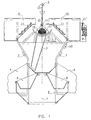
- Figure 1 shows an embodiment of a device according to the invention in the form of a feeding column with several feed troughs.
- a framework 1 having a substantially circular circumference, is disposed around a central axis 2.
- a number of hoppers 9, 10 are located at the upper side of the framework 1. For this purpose, not further shown facilities are fitted to the framework 1 for placing the hoppers 9, 10.
- Each hopper 9, 10 contains a particular sort of feed.
- the framework 1 is provided with partitions 4 which are detachably disposed on the framework 1.
- Feed troughs 6 for the animals are disposed in a circular arrangement in the lower part of the feeding column.
- the geometry of the feeding column it is achieved that the construction occupies little space, while the accessibility of the feeding column to the animals is optimal from all directions.
- the feeding column further comprises conveying means comprising a first conveyor 11 and a second conveyor 3 for conveying feed from the hopper 9, respectively 10 to the relevant feed trough 6.
- the feed can be conveyed directly from the hoppers 9, 10 to the feed troughs 6.
- a receptacle 12 for example centrally located, receiving an amount of feed conveyed by the first conveyor 11 from the hopper 9, 10 to the receptacle 12.
- a first conveyor 11 an auger, gripper, belt conveyor or any other device known per se for conveying feed may be used.
- a second conveyor 3 preferably a tube-shaped chute or a channel-shaped chute, is suitable for conveying the amount of feed from the receptacle 12 to the relevant feed trough 6.
- the tube-shaped chute 3 is rotatably mounted in the feeding column.
- the tube-shaped chute or the channel-shaped chute is preferably made of stainless steel.
- the feeding column is provided with a second control device 19.
- Said second control device 19 controls, under the control of a computer 8 (to which it is connected, for example through a line), the components of the feeding column in such a way that sorts of feed with a particular energy content and/or a particular content of feed components are supplied, in a particular sequence and/or ratio and in a particular amount, to the feed trough 6, the free amount of feed an animal consumes and the desired total amount of energy and/or feed component being taken into account, of course.
- the feeding column may be provided with feed-determining means 5 for determining the sort of feed in a hopper 9, 10.
- feed-determining means may comprise, for example, an olfactometer, a colour meter or image identification equipment (such as described, for example, in U.S. patent 4,843,561).
- the receptacle 12 has a bottom which is adapted to be opened.
- the bottom of the receptacle 12 has two halves 16 and 17 which are hingeable about an axis 15. When the halves 16, 17 move away from each other, there is thus created a chute aperture 18 through which the amount of a sort of feed 14 falls into the tube-shaped chute 3.
- the second control device 19 although another control device may serve as well for the purpose, controls the opening of the bottom of the receptacle 12. Said second control device 19 preferably also controls the sequence of functioning of the first and second conveyors 11 respectively 3, so that the supply of the sorts of feed can take place quickly.
- identification means 7 for identifying an individual animal.
- the identification means 7 are disposed on the framework 1, but it will be obvious that the identification means can also be disposed at other places, such as, for example, the feed troughs 6.
- the identification means 7 With the aid of the identification means 7, the presence of an animal at the feed trough is detected automatically, and the identity of an animal present at a feed trough 6 is determined automatically.
- the amounts of sorts of feed intended for that animal can then be supplied in a particular ratio and/or sequence.
- the aid of a weighing device 20 known per se the amount conveyed to the receptacle 12 by the first conveyor 11 can then be checked.
- the second control device 19 further controls, with the aid of data from the computer 8 and the animal identification means 7, the movement of the tube-shaped chute 3, so that the latter is located just over the correct feed trough 6.
- the second control device 19 further controls, under the control of the computer 8, the drive of the conveyors 11.
- FIG. 2 is a side view of an embodiment of a device according to the invention in the form of a milking box 22.
- the milking box 22 comprises a fencing 23 disposed near the circumference of a cow 24 during her stay in the milking box 22.
- the milking robot 25 comprises, for example, a robot arm 26 having at its end teat cups 28 supported by a carrier 27.
- a sensor 29 with the aid of which the position of the teats of a cow to be milked can be determined.
- a feed trough 31 is fastened to a post 30.
- the feed trough 31 is connected with a post 30 by means of a parallelogram hinge construction 32.
- the feed trough 31 is supported at its lower side by a supporting beam 33.
- a measuring device 34 by means of which the weight of the feed trough 31 with contents can be determined.
- the measuring device 34 comprises a piezo-element. It will be obvious that the invention is not limited to this specific way in which the contents of the feed trough can be measured, and hereinafter some alternative ways of determining the weight of the feed trough with contents will be described.
- a feeding station 35 comprising a number of hoppers (not shown in the drawing), each for containing one sort of feed with its own energy content and/or content of feed components, and a tube-shaped chute (analogously to the feeding column as described above).
- the feeding station 35 comprises a reservoir 36 surrounding the hoppers for the sorts of feed.
- a receiver 37 constituting part of identification means which are not shown in further detail.
- the receiver 37 can receive the signals from a transmitter 38 disposed, for example, on a collar 39 around the neck of the cow 24. It will be obvious that different sorts of identification means are applicable in the invention and that the invention is not limited to one sort of identification means.
- the receiver and the transmitter may further be disposed at different places.
- the receiver may be disposed, for example, on the feed trough 31 and the transmitter may be implanted in the cow.
- a liquid-supplying device 40 for example a sprayer, with the aid of which an amount of liquid, for example water, or a viscous liquid, such as syrup or treacle, can be added to the feed present in the feed trough 31.
- the device operates as follows:
- the cow 24 After the cow 24 has entered the milking box 22 and the transmitter 38 has come into the receiving range of the receiver 37, the cow 24 is identified automatically by the identification means.
- a memory 41 of a computer 42 belonging to a first control device 13, there are stored per cow data in relation to the sorts of feed and the amount thereof a relevant animal is offered per feeding, the free amount of feed and the desired total energy content and/or content of feed components being taken into account, of course.
- the first control device 13 is controlled by the computer 8 which is, for example, connected in a wireless manner with the first control device 13.
- each control device as well as the computer is provided with a transmitter-receiver 21, 21'.
- the identification means send a signal to the computer 42 which, with the aid of the data stored in the memory 41, controls the feeding station 35 in such a way that an amount (portion size) and ratio of sorts of feed belonging to the cow 24 are supplied, if desired, in a particular sequence.
- Data, if any, for the first use of the device according to the invention can be inputted into the memory 41 by making use of inputting means, such as a keyboard 43.
- the computer 42 comprises a display screen 44.
- the feeding station preferably comprises measuring means 45 for measuring the atmospheric conditions, such as temperature, air humidity, atmospheric pressure, wind speed and the like.
- the following data are thus stored in the memory: the amount consumed per sort of feed, the temperature, the air humidity, the atmospheric pressure, the wind speed, the milk yield and possibly the sequence of sorts of feed supplied.
- these data are processed in the memory by the computer.
- the liquid-supplying device 40 may be provided with a heating device or cooling device 46 for the liquid.
- the operation of the heating/cooling device 46 can also be controlled by the computer 42.
- the device is provided with an additive device 47 for adding additives to the feed.
- Said additive device can be controlled by the computer 42, which controls, for example, a valve 48 in dependence on data from the identification means and data from the memory 41. This means that particular additives, such as medicines and the like, can be added automatically to the feed for each individual cow.
- the measuring device 34 By means of the measuring device 34, it is further determined how much feed a relevant cow has consumed during the feeding time.
- the amount of the sort of feed and the amount of liquid added can also be determined separately. These data can be used for continuously updating the data in the memory and, if desired, adapting them to a changing eating behaviour of the cow.
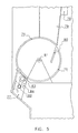
- FIG 3 shows schematically a first embodiment of a feed trough 49 for containing feed.
- An entrance opening 50 gives an animal, for example but not exclusively a cow, access to the feed trough 49.
- An identification device known per se i.e. an animal identification device 51, is disposed near the feed trough 49 and recognises a particular animal approaching the feed trough 49 and wishing to make use of it.
- a control device 52 supplies an amount of a particular sort of feed to the feed trough 49, the amount of said sort of feed falling into the feed trough 49 via, for example, a tube-shaped chute 53.
- the means for weighing the feed present in the feed trough are preferably connected with the control device for supplying, with the aid of data both from the animal identification device and the means for weighing, an amount of a sort of feed to the feed trough, it thus being possible to take the amount of a sort of feed left by the previous animal into account.
- the means for weighing the feed present in the feed trough 49 comprise a feed trough 49 which is pivotable about a pivot axis 56.
- the degree of pivoting is determined by the weight of the feed present in the feed trough 49.
- the device 57 for determining the degree of pivoting of the feed trough 49 comprises a measuring roll 58 which is in contact with the feed trough. From the degree of rotation of the measuring roll 58 the degree of pivoting and thus the amount of feed in the feed trough 49 can be determined.
- the pivoting-determination device 70 for determining the degree of pivoting of the feed trough 60, and for deducing therefrom the weight of the feed present in the feed trough 60 may comprise a dynamometer 71.
- the feed trough 60 bears on the dynamometer 71 via a supporting arm 72. In this situation the feed trough 60 pivots about a pivot axis 73.
- the dynamometer 71 is preferably included in the animal identification device 62.
- a safety support cam 59 ( Figure 3), respectively 74 ( Figure 4), for supporting the feed trough 49; 60.
- the means for weighing the feed present in the feed unit comprise a movable feed trough 75.
- the feed trough 75 is moved in a reciprocating manner by the motor 82 by which the roll 83 is driven.
- a torque whose magnitude is determined by a device 84 for measuring the magnitude of the torque. From the torque determined the device 84 deduces the weight of the amount of a sort of feed present in the feed trough. The exact correlation between torque and amount of feed can previously be determined by simple calibration tests.
- the embodiment according to Figure 5 has a compact construction because of the fact that the motor 82 for moving the feed trough 75, and the device 84 for measuring the magnitude of the torque during moving and for deducing the weight of the amount of the sort of feed present in the feed trough 75 from the measured magnitude of the torque, are integrated in the animal identification device 77.
- the feed trough may be provided with means for holding back an animal wishing to make use of the feed trough at an undesired point of time, or preventing that animal or making it impossible for that animal to make further use of the feed trough (for example for the remaining sorts of feed), with the aid of data from the animal identification device.
- the means for holding back an animal comprise a loudspeaker 55 for issuing an animal-deterring sound.
- the means for holding back an animal may comprise a lighting device 54 for producing an animal-deterring light.
- the use of deterring light is recommendable, because this light can be focussed such that it only produces an effect on one particular feed trough.
- the means for holding back an animal comprise a closing element 65 which is movable across the entrance opening 61.
- the closing element 65 is a vessel-shaped element which is capable of rotating about an axis 66.
- Said axis 66 may be a motor-driven axis, said motor being controlled with the aid of data from the animal identification device 62.
- a voltage-supplying device 67 for supplying an animal-deterring electric tension to the closing element 65.
- Non-eligible animals approaching the feed trough 60 often make contact with the feed trough 60. They will in particular touch the closing element 65 with their noses.
- By connecting precisely those components of the feed trough that are regularly touched by animals with the voltage-supplying device 67 it is possible to deter a particular animal very locally. Accordingly, such a voltage-supplying device 67 can also be used per se independently of a closing element.
- the second embodiment also comprises a control device 63 and a tube-shaped chute 64 for the feed.
- the devices described can be designed extremely compactly if the means for holding back an animal are integrated in the animal identification device. Alternatively, the means for holding back an animal may be separate means.
- the closing element is constituted by the feed trough 75 itself which is designed movably.
- the feed trough 75 is rotatably disposed about an axis 81, which axis 81 may be a motor-driven axis, said motor being controlled by the animal identification device.
- the feed trough 75 is provided with a wall portion 80 for catching remaining feed.
- Said wall portion 80 can also act as a feed-guiding element for feed supplied through the tube-shaped chute 79 to the feed trough 75.
- a simple but reliable construction because of the fact that the closing element rotates about an axis, the closing element being driven by a motor controlled by the animal identification device.
- a roll 69 respectively 83 is preferably driven by a motor 68 respectively 82, said roll 69, 83 being in contact with the closing element 65 respectively 75.
- the feed trough 75 thus bears on the animal identification device 77 via the roll 83.
- the roll 83 preferably performs both the function of driving the closing element, in this case the feed trough 75 itself, and the function of torque roll or measuring roll.
- the torque can also be measured via that motor.
- the fourth embodiment comprises means for holding back, with the aid of data from the animal identification device 87, an animal wishing to make use of the feed trough 85, as well as means for weighing the feed present in the feed trough 85.
- the means for holding back are constituted by a separate closing element 91, which is rotatable about an axis 90.
- the closing element 91 is set in rotation by a roll 92, which is capable of coming into contact with the closing element 91, and is driven by a motor 93, which is controlled by the animal identification device 87. This makes it possible, for example, to refuse access to a feed trough to an animal jostling another animal from that feed trough.
- the weighing means are constituted by a feed trough 85 which is rotatable about an axis 94.
- the feed unit 85 can be brought into contact with the roll 92, and is subjected to a reciprocating movement by correct operation of the motor 93 by which the roll 92 is driven.
- the roll 92 makes contact with the feed trough 85, and the latter can be set in motion to determine the amount of the sort of feed present in the feed trough 85. After an animal has consumed the sort of feed, the amount of remaining sort of feed can be determined by torque measurement. Then the roll 92 is controlled by the motor 93 in such a way that it partially covers the entrance opening 86. A catching device 96 on the feed trough 85 takes along the closing element 91 until the latter comes into contact with the roll 92. Then the roll 92 controls the closing element 91 in such a way that the latter covers the entire entrance opening 86. Owing to the fact that the feed trough 85 is no longer in contact with the roll 92, it falls back to the starting position in which a next sort of feed can be supplied, if desired, via the tube-shaped chute or channel-shaped chute 89.
- the fifth embodiment according to Figure 7 differs from that of Figure 6 by the location of the pivot axis 104 about which the feed trough 97 rotates.
- the pivot axis 104 is disposed close to the roll 101 for driving the feed trough 97 and measuring the torque, for the purpose of measuring very small differences in amount of feed.
- the closing element 100 for closing the entrance opening 98 pivots about the axis 102.
- the supply of feed to a feed trough is performed depending on the free feed consumption of an animal in a period having a predetermined length, for example one day (although other periods are also possible).
- the device for supplying feed is controlled in such a way that feed is supplied unlimitedly to the animal during a period having the predetermined length.
- the consumption data are supplied to the computer 8 which determines the total free amount of feed consumed. Such a determination may take place periodically in order to be able to take a possible development in the eating behaviour of the animal into account.
- the computer controls the device in such a way that the mutual ratio of the sorts of feed to be offered is such that said amount of nutritional energy and/or the total amount of feed component is attained by means of the determined free amount of feed, i.e. 45 kg in the present embodiment.
- a total of 12 kg concentrate, 24 kg silage, 6 kg maize and 3 kg brewer's grains is offered to the cow per day.
- feed is supplied unlimitedly to an animal, and the free amount of feed consumed by that animal in a period having a predetermined length, for example one day, is each time recorded.
- the energy content and/or the content of feed components of the feed to be supplied is adapted in order to obtain the desired total energy content and/or the desired total content of feed component for said period.
- a blocking time of, for example, 30 minutes can be set, which means that within the blocking time, after a feed supply at which a cow has eaten, the cow is not admitted to the feed trough or is not supplied with feed again. Also when the cow is expected at the milking box within the blocking time of half an hour, the access will be refused.
- the relevant points of time such as the point of time of feed supply or the point of time when the cow leaves the feed trough (after having eaten or not) are stored. It will be obvious that, when the device is used for determining the free feed consumption, said blocking time is set at zero.
- the feed offered per day may consist of 14 kg concentrate, 14 kg silage, 6 kg maize and 4 kg brewer's grains. Consequently, the latter cow is offered food with a higher energy content than the previously mentioned cow.
Landscapes
- Life Sciences & Earth Sciences (AREA)
- Environmental Sciences (AREA)
- Birds (AREA)
- Animal Husbandry (AREA)
- Biodiversity & Conservation Biology (AREA)
- Feeding And Watering For Cattle Raising And Animal Husbandry (AREA)
Applications Claiming Priority (2)
| Application Number | Priority Date | Filing Date | Title |
|---|---|---|---|
| NL1024675 | 2003-10-31 | ||
| NL1024675A NL1024675C2 (nl) | 2003-10-31 | 2003-10-31 | Inrichting en werkwijze voor het automatisch afgeven van voeder aan een dier. |
Publications (3)
| Publication Number | Publication Date |
|---|---|
| EP1527680A2 true EP1527680A2 (fr) | 2005-05-04 |
| EP1527680A3 EP1527680A3 (fr) | 2006-02-01 |
| EP1527680B1 EP1527680B1 (fr) | 2007-02-28 |
Family
ID=34420831
Family Applications (1)
| Application Number | Title | Priority Date | Filing Date |
|---|---|---|---|
| EP04077797A Revoked EP1527680B1 (fr) | 2003-10-31 | 2004-10-11 | Dispositif et procédé de distribution automatique d'alimentation pour animaux |
Country Status (5)
| Country | Link |
|---|---|
| EP (1) | EP1527680B1 (fr) |
| AT (1) | ATE354946T1 (fr) |
| DE (1) | DE602004004971T2 (fr) |
| DK (1) | DK1527680T3 (fr) |
| NL (1) | NL1024675C2 (fr) |
Cited By (4)
| Publication number | Priority date | Publication date | Assignee | Title |
|---|---|---|---|---|
| EP2605640B1 (fr) | 2010-08-16 | 2015-04-08 | Dairymaster | Appareil de distribution d'aliments pour animaux et système de distribution d'aliments pour animaux |
| CN107667991A (zh) * | 2017-10-31 | 2018-02-09 | 广西民族大学 | 一种桑蚕智能喂食系统 |
| CN109430106A (zh) * | 2018-12-10 | 2019-03-08 | 三峡大学 | 散养鸡螺旋输送喂食装置及其出料方法 |
| CN116849183A (zh) * | 2023-07-07 | 2023-10-10 | 深圳市微米生物技术有限公司 | 一种高效环保的蝇蛆养殖用智能繁衍箱 |
Family Cites Families (1)
| Publication number | Priority date | Publication date | Assignee | Title |
|---|---|---|---|---|
| NL1019093C2 (nl) * | 2001-10-03 | 2003-04-07 | Lely Entpr Ag | Inrichting voor het automatisch in een periode met een bepaalde lengte afgeven van een bepaalde hoeveelheid voeder aan een dier. |
-
2003
- 2003-10-31 NL NL1024675A patent/NL1024675C2/nl not_active IP Right Cessation
-
2004
- 2004-10-11 AT AT04077797T patent/ATE354946T1/de not_active IP Right Cessation
- 2004-10-11 EP EP04077797A patent/EP1527680B1/fr not_active Revoked
- 2004-10-11 DE DE602004004971T patent/DE602004004971T2/de not_active Revoked
- 2004-10-11 DK DK04077797T patent/DK1527680T3/da active
Cited By (5)
| Publication number | Priority date | Publication date | Assignee | Title |
|---|---|---|---|---|
| EP2605640B1 (fr) | 2010-08-16 | 2015-04-08 | Dairymaster | Appareil de distribution d'aliments pour animaux et système de distribution d'aliments pour animaux |
| CN107667991A (zh) * | 2017-10-31 | 2018-02-09 | 广西民族大学 | 一种桑蚕智能喂食系统 |
| CN107667991B (zh) * | 2017-10-31 | 2022-11-11 | 广西民族大学 | 一种桑蚕智能喂食系统 |
| CN109430106A (zh) * | 2018-12-10 | 2019-03-08 | 三峡大学 | 散养鸡螺旋输送喂食装置及其出料方法 |
| CN116849183A (zh) * | 2023-07-07 | 2023-10-10 | 深圳市微米生物技术有限公司 | 一种高效环保的蝇蛆养殖用智能繁衍箱 |
Also Published As
| Publication number | Publication date |
|---|---|
| NL1024675C2 (nl) | 2005-05-03 |
| EP1527680A3 (fr) | 2006-02-01 |
| DK1527680T3 (da) | 2007-06-25 |
| DE602004004971D1 (de) | 2007-04-12 |
| ATE354946T1 (de) | 2006-03-15 |
| EP1527680B1 (fr) | 2007-02-28 |
| DE602004004971T2 (de) | 2007-10-31 |
Similar Documents
| Publication | Publication Date | Title |
|---|---|---|
| EP1300073B1 (fr) | Dispositif pour distribuer une quantité d'alimentation prédéterminée à un animal dans une période de temps prédéterminée | |
| EP1300074B1 (fr) | Dispositif pour fournir automatiquement une quantité prédéfinie d'aliment à un animal en une période de temps prédéfinie | |
| EP1300075B1 (fr) | Dispositif de distribution automatique d'alimentation pour animaux | |
| EP1260136B1 (fr) | Dispositif pour la distribution de nourriture à des animaux | |
| AU2002301290B2 (en) | An assembly for automatically supplying an amount of feed to a dairy animal in a predetermined period | |
| EP1250839B1 (fr) | Dispositif pour la distribution de nourriture aux animaux | |
| JP2003009698A (ja) | 動物用飼料供給装置 | |
| EP1527680B1 (fr) | Dispositif et procédé de distribution automatique d'alimentation pour animaux | |
| EP1300072B1 (fr) | Dispositif et procédé de distribution automatique d'au moins deux sortes de fourrage à des animaux | |
| JP2002360096A (ja) | 動物への飼料供給装置 | |
| Dawson | Equipment for feeding concentrates in and out of the parlour |
Legal Events
| Date | Code | Title | Description |
|---|---|---|---|
| PUAI | Public reference made under article 153(3) epc to a published international application that has entered the european phase |
Free format text: ORIGINAL CODE: 0009012 |
|
| AK | Designated contracting states |
Kind code of ref document: A2 Designated state(s): AT BE BG CH CY CZ DE DK EE ES FI FR GB GR HU IE IT LI LU MC NL PL PT RO SE SI SK TR |
|
| AX | Request for extension of the european patent |
Extension state: AL HR LT LV MK |
|
| PUAL | Search report despatched |
Free format text: ORIGINAL CODE: 0009013 |
|
| AK | Designated contracting states |
Kind code of ref document: A3 Designated state(s): AT BE BG CH CY CZ DE DK EE ES FI FR GB GR HU IE IT LI LU MC NL PL PT RO SE SI SK TR |
|
| AX | Request for extension of the european patent |
Extension state: AL HR LT LV MK |
|
| 17P | Request for examination filed |
Effective date: 20060322 |
|
| GRAP | Despatch of communication of intention to grant a patent |
Free format text: ORIGINAL CODE: EPIDOSNIGR1 |
|
| AKX | Designation fees paid |
Designated state(s): AT BE BG CH CY CZ DE DK EE ES FI FR GB GR HU IE IT LI LU MC NL PL PT RO SE SI SK TR |
|
| GRAS | Grant fee paid |
Free format text: ORIGINAL CODE: EPIDOSNIGR3 |
|
| GRAA | (expected) grant |
Free format text: ORIGINAL CODE: 0009210 |
|
| AK | Designated contracting states |
Kind code of ref document: B1 Designated state(s): AT BE BG CH CY CZ DE DK EE ES FI FR GB GR HU IE IT LI LU MC NL PL PT RO SE SI SK TR |
|
| PG25 | Lapsed in a contracting state [announced via postgrant information from national office to epo] |
Ref country code: LI Free format text: LAPSE BECAUSE OF FAILURE TO SUBMIT A TRANSLATION OF THE DESCRIPTION OR TO PAY THE FEE WITHIN THE PRESCRIBED TIME-LIMIT Effective date: 20070228 Ref country code: SI Free format text: LAPSE BECAUSE OF FAILURE TO SUBMIT A TRANSLATION OF THE DESCRIPTION OR TO PAY THE FEE WITHIN THE PRESCRIBED TIME-LIMIT Effective date: 20070228 Ref country code: PL Free format text: LAPSE BECAUSE OF FAILURE TO SUBMIT A TRANSLATION OF THE DESCRIPTION OR TO PAY THE FEE WITHIN THE PRESCRIBED TIME-LIMIT Effective date: 20070228 Ref country code: CH Free format text: LAPSE BECAUSE OF FAILURE TO SUBMIT A TRANSLATION OF THE DESCRIPTION OR TO PAY THE FEE WITHIN THE PRESCRIBED TIME-LIMIT Effective date: 20070228 Ref country code: AT Free format text: LAPSE BECAUSE OF FAILURE TO SUBMIT A TRANSLATION OF THE DESCRIPTION OR TO PAY THE FEE WITHIN THE PRESCRIBED TIME-LIMIT Effective date: 20070228 Ref country code: FI Free format text: LAPSE BECAUSE OF FAILURE TO SUBMIT A TRANSLATION OF THE DESCRIPTION OR TO PAY THE FEE WITHIN THE PRESCRIBED TIME-LIMIT Effective date: 20070228 Ref country code: BE Free format text: LAPSE BECAUSE OF FAILURE TO SUBMIT A TRANSLATION OF THE DESCRIPTION OR TO PAY THE FEE WITHIN THE PRESCRIBED TIME-LIMIT Effective date: 20070228 |
|
| REG | Reference to a national code |
Ref country code: GB Ref legal event code: FG4D |
|
| REG | Reference to a national code |
Ref country code: CH Ref legal event code: EP |
|
| REF | Corresponds to: |
Ref document number: 602004004971 Country of ref document: DE Date of ref document: 20070412 Kind code of ref document: P |
|
| REG | Reference to a national code |
Ref country code: IE Ref legal event code: FG4D |
|
| PG25 | Lapsed in a contracting state [announced via postgrant information from national office to epo] |
Ref country code: BG Free format text: LAPSE BECAUSE OF FAILURE TO SUBMIT A TRANSLATION OF THE DESCRIPTION OR TO PAY THE FEE WITHIN THE PRESCRIBED TIME-LIMIT Effective date: 20070529 |
|
| REG | Reference to a national code |
Ref country code: SE Ref legal event code: TRGR |
|
| PG25 | Lapsed in a contracting state [announced via postgrant information from national office to epo] |
Ref country code: ES Free format text: LAPSE BECAUSE OF FAILURE TO SUBMIT A TRANSLATION OF THE DESCRIPTION OR TO PAY THE FEE WITHIN THE PRESCRIBED TIME-LIMIT Effective date: 20070608 |
|
| REG | Reference to a national code |
Ref country code: DK Ref legal event code: T3 |
|
| PG25 | Lapsed in a contracting state [announced via postgrant information from national office to epo] |
Ref country code: PT Free format text: LAPSE BECAUSE OF FAILURE TO SUBMIT A TRANSLATION OF THE DESCRIPTION OR TO PAY THE FEE WITHIN THE PRESCRIBED TIME-LIMIT Effective date: 20070730 |
|
| REG | Reference to a national code |
Ref country code: CH Ref legal event code: PL |
|
| ET | Fr: translation filed | ||
| PG25 | Lapsed in a contracting state [announced via postgrant information from national office to epo] |
Ref country code: SK Free format text: LAPSE BECAUSE OF FAILURE TO SUBMIT A TRANSLATION OF THE DESCRIPTION OR TO PAY THE FEE WITHIN THE PRESCRIBED TIME-LIMIT Effective date: 20070228 |
|
| PLBI | Opposition filed |
Free format text: ORIGINAL CODE: 0009260 |
|
| PG25 | Lapsed in a contracting state [announced via postgrant information from national office to epo] |
Ref country code: RO Free format text: LAPSE BECAUSE OF FAILURE TO SUBMIT A TRANSLATION OF THE DESCRIPTION OR TO PAY THE FEE WITHIN THE PRESCRIBED TIME-LIMIT Effective date: 20070228 Ref country code: CZ Free format text: LAPSE BECAUSE OF FAILURE TO SUBMIT A TRANSLATION OF THE DESCRIPTION OR TO PAY THE FEE WITHIN THE PRESCRIBED TIME-LIMIT Effective date: 20070228 |
|
| PLAX | Notice of opposition and request to file observation + time limit sent |
Free format text: ORIGINAL CODE: EPIDOSNOBS2 |
|
| 26 | Opposition filed |
Opponent name: DELAVAL INTERNATIONAL AB PATENT & TRADEMARK DEPART Effective date: 20071128 |
|
| NLR1 | Nl: opposition has been filed with the epo |
Opponent name: DELAVAL INTERNATIONAL AB PATENT & TRADEMARK DEPART |
|
| PG25 | Lapsed in a contracting state [announced via postgrant information from national office to epo] |
Ref country code: IT Free format text: LAPSE BECAUSE OF FAILURE TO SUBMIT A TRANSLATION OF THE DESCRIPTION OR TO PAY THE FEE WITHIN THE PRESCRIBED TIME-LIMIT Effective date: 20070228 Ref country code: GR Free format text: LAPSE BECAUSE OF FAILURE TO SUBMIT A TRANSLATION OF THE DESCRIPTION OR TO PAY THE FEE WITHIN THE PRESCRIBED TIME-LIMIT Effective date: 20070529 |
|
| PLAF | Information modified related to communication of a notice of opposition and request to file observations + time limit |
Free format text: ORIGINAL CODE: EPIDOSCOBS2 |
|
| PG25 | Lapsed in a contracting state [announced via postgrant information from national office to epo] |
Ref country code: MC Free format text: LAPSE BECAUSE OF NON-PAYMENT OF DUE FEES Effective date: 20071031 |
|
| PLBB | Reply of patent proprietor to notice(s) of opposition received |
Free format text: ORIGINAL CODE: EPIDOSNOBS3 |
|
| PG25 | Lapsed in a contracting state [announced via postgrant information from national office to epo] |
Ref country code: IE Free format text: LAPSE BECAUSE OF NON-PAYMENT OF DUE FEES Effective date: 20071011 |
|
| PG25 | Lapsed in a contracting state [announced via postgrant information from national office to epo] |
Ref country code: EE Free format text: LAPSE BECAUSE OF FAILURE TO SUBMIT A TRANSLATION OF THE DESCRIPTION OR TO PAY THE FEE WITHIN THE PRESCRIBED TIME-LIMIT Effective date: 20070228 |
|
| PGFP | Annual fee paid to national office [announced via postgrant information from national office to epo] |
Ref country code: DE Payment date: 20081201 Year of fee payment: 5 |
|
| PGFP | Annual fee paid to national office [announced via postgrant information from national office to epo] |
Ref country code: SE Payment date: 20081029 Year of fee payment: 5 |
|
| PLAB | Opposition data, opponent's data or that of the opponent's representative modified |
Free format text: ORIGINAL CODE: 0009299OPPO |
|
| R26 | Opposition filed (corrected) |
Opponent name: DELAVAL INTERNATIONAL AB PATENT & TRADEMARK DEPART Effective date: 20071128 |
|
| RDAF | Communication despatched that patent is revoked |
Free format text: ORIGINAL CODE: EPIDOSNREV1 |
|
| PG25 | Lapsed in a contracting state [announced via postgrant information from national office to epo] |
Ref country code: CY Free format text: LAPSE BECAUSE OF FAILURE TO SUBMIT A TRANSLATION OF THE DESCRIPTION OR TO PAY THE FEE WITHIN THE PRESCRIBED TIME-LIMIT Effective date: 20070228 |
|
| NLR1 | Nl: opposition has been filed with the epo |
Opponent name: DELAVAL INTERNATIONAL AB PATENT & TRADEMARK DEPART |
|
| PG25 | Lapsed in a contracting state [announced via postgrant information from national office to epo] |
Ref country code: LU Free format text: LAPSE BECAUSE OF NON-PAYMENT OF DUE FEES Effective date: 20071011 |
|
| PG25 | Lapsed in a contracting state [announced via postgrant information from national office to epo] |
Ref country code: HU Free format text: LAPSE BECAUSE OF FAILURE TO SUBMIT A TRANSLATION OF THE DESCRIPTION OR TO PAY THE FEE WITHIN THE PRESCRIBED TIME-LIMIT Effective date: 20070901 Ref country code: TR Free format text: LAPSE BECAUSE OF FAILURE TO SUBMIT A TRANSLATION OF THE DESCRIPTION OR TO PAY THE FEE WITHIN THE PRESCRIBED TIME-LIMIT Effective date: 20070228 |
|
| RDAG | Patent revoked |
Free format text: ORIGINAL CODE: 0009271 |
|
| STAA | Information on the status of an ep patent application or granted ep patent |
Free format text: STATUS: PATENT REVOKED |
|
| 27W | Patent revoked |
Effective date: 20090624 |
|
| GBPR | Gb: patent revoked under art. 102 of the ep convention designating the uk as contracting state |
Effective date: 20090624 |
|
| PGFP | Annual fee paid to national office [announced via postgrant information from national office to epo] |
Ref country code: DK Payment date: 20091026 Year of fee payment: 6 |
|
| NLR2 | Nl: decision of opposition |
Effective date: 20090624 |
|
| REG | Reference to a national code |
Ref country code: SE Ref legal event code: ECNC |
|
| PGFP | Annual fee paid to national office [announced via postgrant information from national office to epo] |
Ref country code: NL Payment date: 20091024 Year of fee payment: 6 |
|
| PGFP | Annual fee paid to national office [announced via postgrant information from national office to epo] |
Ref country code: FR Payment date: 20091029 Year of fee payment: 6 Ref country code: GB Payment date: 20091026 Year of fee payment: 6 |