EP1527656B1 - Induction hot plate comprising heating regions having a reconfigurable structure, and method for increasing the maximum power of said heating regions - Google Patents
Induction hot plate comprising heating regions having a reconfigurable structure, and method for increasing the maximum power of said heating regions Download PDFInfo
- Publication number
- EP1527656B1 EP1527656B1 EP03766164A EP03766164A EP1527656B1 EP 1527656 B1 EP1527656 B1 EP 1527656B1 EP 03766164 A EP03766164 A EP 03766164A EP 03766164 A EP03766164 A EP 03766164A EP 1527656 B1 EP1527656 B1 EP 1527656B1
- Authority
- EP
- European Patent Office
- Prior art keywords
- induction
- power
- induction heating
- heating
- heating element
- Prior art date
- Legal status (The legal status is an assumption and is not a legal conclusion. Google has not performed a legal analysis and makes no representation as to the accuracy of the status listed.)
- Expired - Lifetime
Links
- 238000010438 heat treatment Methods 0.000 title claims abstract description 117
- 230000006698 induction Effects 0.000 title claims abstract description 65
- 238000000034 method Methods 0.000 title claims description 3
- 238000010411 cooking Methods 0.000 claims description 14
Images
Classifications
-
- H—ELECTRICITY
- H05—ELECTRIC TECHNIQUES NOT OTHERWISE PROVIDED FOR
- H05B—ELECTRIC HEATING; ELECTRIC LIGHT SOURCES NOT OTHERWISE PROVIDED FOR; CIRCUIT ARRANGEMENTS FOR ELECTRIC LIGHT SOURCES, IN GENERAL
- H05B6/00—Heating by electric, magnetic or electromagnetic fields
- H05B6/02—Induction heating
- H05B6/06—Control, e.g. of temperature, of power
- H05B6/062—Control, e.g. of temperature, of power for cooking plates or the like
- H05B6/065—Control, e.g. of temperature, of power for cooking plates or the like using coordinated control of multiple induction coils
-
- H—ELECTRICITY
- H05—ELECTRIC TECHNIQUES NOT OTHERWISE PROVIDED FOR
- H05B—ELECTRIC HEATING; ELECTRIC LIGHT SOURCES NOT OTHERWISE PROVIDED FOR; CIRCUIT ARRANGEMENTS FOR ELECTRIC LIGHT SOURCES, IN GENERAL
- H05B6/00—Heating by electric, magnetic or electromagnetic fields
- H05B6/02—Induction heating
- H05B6/06—Control, e.g. of temperature, of power
-
- H—ELECTRICITY
- H05—ELECTRIC TECHNIQUES NOT OTHERWISE PROVIDED FOR
- H05B—ELECTRIC HEATING; ELECTRIC LIGHT SOURCES NOT OTHERWISE PROVIDED FOR; CIRCUIT ARRANGEMENTS FOR ELECTRIC LIGHT SOURCES, IN GENERAL
- H05B6/00—Heating by electric, magnetic or electromagnetic fields
- H05B6/02—Induction heating
- H05B6/10—Induction heating apparatus, other than furnaces, for specific applications
- H05B6/12—Cooking devices
-
- H—ELECTRICITY
- H05—ELECTRIC TECHNIQUES NOT OTHERWISE PROVIDED FOR
- H05B—ELECTRIC HEATING; ELECTRIC LIGHT SOURCES NOT OTHERWISE PROVIDED FOR; CIRCUIT ARRANGEMENTS FOR ELECTRIC LIGHT SOURCES, IN GENERAL
- H05B2213/00—Aspects relating both to resistive heating and to induction heating, covered by H05B3/00 and H05B6/00
- H05B2213/05—Heating plates with pan detection means
Definitions
- the present invention relates to an induction hob according to the preamble of the first claim.
- European patent application EP 0844807 which belongs to the same assignee as the present invention and which describes the best possible control of the power installed in domestic induction hobs with a reconfigurable topology which allows the independent supply of two coils, which are the heating elements, with a power adjustable up to their nominal values.
- EP 0844807 allows the use of the installed total power and its use for feeding each of the coils so that it allows ultrafast heating with a power capacity greater than the nominal power of the coil without increasing the nominal characteristics of the system.
- the object of the present invention is to provide an induction hob comprising at least one heating zone formed by two independent heating zones, to which each of them is assigned an induction heating element, such that one or two of the zones depend on the size of the container to be heated can be activated in such a way that the maximum heating power can be increased to shorten the heating time, such as to shorten the time it takes to achieve a first boil.
- the invention consists of a new induction hob of the type comprising at least two power modules, each of which supplies an electrical power to at least a first induction heating element and a second induction heating element, each associated with a heating zone for a cooking product container in that the power module for increasing the maximum heating power of the first induction heating element interrupts the power supply to the second induction heating element.
- the most important novelty of the invention is based on the feature that the heating zones of the first induction heating elements of the two power modules together form a common heating zone and, moreover, to increase the maximum heating power in the common heating zone, the two power modules provide their respective total power to the first induction heating elements, so that the Heating time of Gargut proceedingsnisses is considerably shortened.
- the common heating zone is realized as a heating zone with two circuits, which are associated with an outer annular heating zone and an inner heating zone, which are each associated with one of the two first induction heating.
- the invention provides for the inclusion of a device for detecting the container, such as a pot, to determine the size of the bottom surface of a parked on the common heating zone Gargut mattersnisses.
- the two power modules Depending on the size, which is detected by the device for detecting the size of the bottom surface of the Gargut mattersnisses, lead the two power modules their overall performance only from a certain size of the bottom surface of the Gargut mattersnisses the first induction heating of the common heating zone.
- the detected size of the bottom surface of the food container is smaller than a certain size, then only one of the power modules will provide its total power to the associated first common heating zone induction heating element.
- the invention provides to allow the increase of the maximum heating power of one of the second induction heating elements, for which purpose each of the power modules interrupts the power supply to the respective first induction heating element and provides its total power to the second induction heating element.
- the invention also relates to a method for increasing the maximum heating power of heating zones for food containers in an induction hob, which has at least two power modules, wherein via each of them an electrical power is supplied to at least a first induction heating element and a second induction heating element, respectively one of the heating zones is assigned, which power module to increase the maximum heating power of the first induction heating interrupts the power supply to the second induction heating and provides its total power to the first induction heating, and is characterized in that the heating zones of the first induction heating of the two power modules together form a common heating zone , And that also to increase the maximum heating power of the common heating zone, the first induction heating the respective total power of the two power modules supplied becomes.
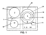
- the hob of the embodiment of the invention comprises two power modules 1 and 3, of which each first induction heating elements 5 and 9 and second induction heating elements 7 and 11 can supply electrical power.
- Each of the induction heating elements is assigned a heating zone of a food container 21, such as a pot, so that the heating zones 13 and 15 are associated with the first heating elements 5 and 9 and the heating zones 17 and 19 are associated with the second heating elements 7 and 11.
- the heating zone 15 is an outer annular heating zone and the heating zone 13 is an inner circular heating zone.
- This configuration makes it possible to perform the heating of a food container 21 whose diameter is larger than that of the inner heating zone 13 and smaller than that of the outer heating zone 15.
- the total power provided by each of the two power modules 1 and 3 is provided to the first induction heating elements 5 and 9 so that the maximum power provided thereto is increased and the heating time of the Gargut proceedingsnisses 21 is considerably shortened.
- the invention comprises a device for detecting the size of the bottom surface of the food container 21 (not shown in the figures), which can be formed by series of sensors, so that the total power of the power modules 1 and 2 of the common heating zone 23 are supplied only if the size of the bottom surface of the Gargut inventornisses has a diameter which is greater than that of the inner circular heating zone 13, as can be seen in the figure.
- the size of the bottom of the Gargut mattersnisses 21 has a diameter which is equal to or smaller than that of the inner heating zone 13, only one of the two power modules 1 or 3 provides its total power to the induction heating element 5 of the common heating zone 23, since in this case Due to the smaller size of the heating surface their heating is faster and it is not necessary to provide the power of both power modules 1 and 3.
Landscapes
- Physics & Mathematics (AREA)
- Electromagnetism (AREA)
- Induction Heating Cooking Devices (AREA)
- Cookers (AREA)
- General Induction Heating (AREA)
- Commercial Cooking Devices (AREA)
- Electric Stoves And Ranges (AREA)
Abstract
Description
Die vorliegende Erfindung betrifft ein Induktionskochfeld gemäß dem Oberbegriff des ersten Patentanspruchs.The present invention relates to an induction hob according to the preamble of the first claim.
Den der Erfindung am nächsten stehenden Stand der Technik stellt die europäische Patentanmeldung EP 0844807 dar, welche demselben Inhaber wie die vorliegende Erfindung gehört und in welcher die bestmögliche Steuerung der Leistung beschrieben wird, die in Induktionskochfeldern für den Haushalt mit einer Topologie mit neukonfigurierbarer Struktur installiert ist, welche die unabhängige Speisung zweier Spulen, welche die Heizelemente darstellen, mit einer bis zu ihren Nominalwerten regulierbaren Leistung erlaubt. Außerdem erlaubt sie die Nutzung der installierten Gesamtleistung und ihre Verwendung zur Speisung jeder der Spulen, so dass sie eine ultraschnelle Erwärmung mit einer Leistungskapazität, welche größer als die Nominalleistung der Spule ist, erlaubt, ohne die Nominalkennwerte des Systems zu erhöhen.The closest prior art to the invention is European patent application EP 0844807, which belongs to the same assignee as the present invention and which describes the best possible control of the power installed in domestic induction hobs with a reconfigurable topology which allows the independent supply of two coils, which are the heating elements, with a power adjustable up to their nominal values. In addition, it allows the use of the installed total power and its use for feeding each of the coils so that it allows ultrafast heating with a power capacity greater than the nominal power of the coil without increasing the nominal characteristics of the system.
Die vorliegende Erfindung hat die Aufgabe, ein Induktionskochfeld bereitzustellen, welches zumindest eine Heizzone umfasst, welche durch zwei unabhängige Heizzonen gebildet wird, wozu jeder von ihnen ein Induktionsheizelement zugeordnet ist, so dass eine oder zwei der Zonen in Abhängigkeit von der Größe des zu erwärmenden Behältnisses aktiviert werden können, und zwar derart, dass die maximale Heizleistung erhöht werden kann, um die Heizzeit zu verkürzen, wie zum Beispiel zum Verkürzen der Zeit, welche gebraucht wird, um ein erstes Aufkochen zu erreichen.The object of the present invention is to provide an induction hob comprising at least one heating zone formed by two independent heating zones, to which each of them is assigned an induction heating element, such that one or two of the zones depend on the size of the container to be heated can be activated in such a way that the maximum heating power can be increased to shorten the heating time, such as to shorten the time it takes to achieve a first boil.
Um die zuvor erwähnten Aufgaben zu erreichen, besteht die Erfindung aus einem neuen Induktionskochfeld von der Art, welche zumindest zwei Leistungsmodule umfasst, von welchen jedes eine elektrische Leistung zumindest einem ersten Induktionsheizelement und einem zweiten Induktionsheizelement zuführt, welchen jeweils eine Heizzone für ein Gargutbehältnis zugeordnet ist, welches Leistungsmodui zur Erhöhung der maximalen Heizleistung des ersten Induktionsheizelements die Energiezufuhr zu dem zweiten Induktionsheizelement unterbricht.In order to achieve the objects mentioned above, the invention consists of a new induction hob of the type comprising at least two power modules, each of which supplies an electrical power to at least a first induction heating element and a second induction heating element, each associated with a heating zone for a cooking product container in that the power module for increasing the maximum heating power of the first induction heating element interrupts the power supply to the second induction heating element.
Die wichtigste Neuheit der Erfindung beruht auf dem Merkmal, dass die Heizzonen der ersten Induktionsheizelemente der beiden Leistungsmodule zusammen eine gemeinsame Heizzone bilden und dass außerdem zur Erhöhung der maximalen Heizleistung in der gemeinsamen Heizzone die beiden Leistungsmodule ihre jeweilige Gesamtleistung den ersten Induktionsheizelementen bereitstellen, so dass die Heizzeit des Gargutbehältnisses beträchtlich verkürzt wird.The most important novelty of the invention is based on the feature that the heating zones of the first induction heating elements of the two power modules together form a common heating zone and, moreover, to increase the maximum heating power in the common heating zone, the two power modules provide their respective total power to the first induction heating elements, so that the Heating time of Gargutbehältnisses is considerably shortened.
In einer Ausführungsform der Erfindung ist die gemeinsame Heizzone als eine Heizzone mit zwei Kreisen verwirklicht, welchen eine äußere ringförmige Heizzone und eine innere Heizzone zugeordnet sind, welche je einem der beiden ersten Induktionsheizelemente zugeordnet sind.In one embodiment of the invention, the common heating zone is realized as a heating zone with two circuits, which are associated with an outer annular heating zone and an inner heating zone, which are each associated with one of the two first induction heating.
Die Erfindung sieht die Einbeziehung einer Einrichtung zur Erkennung des Behältnisses, wie zum Beispiel eines Topfes, vor, um die Größe der Bodenfläche eines auf der gemeinsamen Heizzone abgestellten Gargutbehältnisses zu bestimmen.The invention provides for the inclusion of a device for detecting the container, such as a pot, to determine the size of the bottom surface of a parked on the common heating zone Gargutbehältnisses.
In Abhängigkeit von der Größe, welche durch die Einrichtung zur Erkennung der Größe der Bodenfläche des Gargutbehältnisses erfassten wird, führen die beiden Leistungsmodule ihre Gesamtleistungen erst ab einer bestimmten Größe der Bodenfläche des Gargutbehältnisses den ersten Induktionsheizelementen der gemeinsamen Heizzone zu.Depending on the size, which is detected by the device for detecting the size of the bottom surface of the Gargutbehältnisses, lead the two power modules their overall performance only from a certain size of the bottom surface of the Gargutbehältnisses the first induction heating of the common heating zone.
Wenn die erfasste Größe der Bodenfläche des Gargutbehältnisses kleiner als eine bestimmte Größe ist, dann stellt nur eines der Leistungsmodule seine Gesamtleistung dem zugeordneten ersten Induktionsheizelement der gemeinsamen Heizzone bereit.If the detected size of the bottom surface of the food container is smaller than a certain size, then only one of the power modules will provide its total power to the associated first common heating zone induction heating element.
Außerdem sieht die Erfindung vor, die Erhöhung der maximalen Heizleistung eines der zweiten Induktionsheizelemente zu erlauben, wozu jedes der Leistungsmodule die Energiezufuhr zu dem jeweiligen ersten Induktionsheizelement unterbricht und seine Gesamtleistung dem zweiten Induktionsheizelement bereitstellt.In addition, the invention provides to allow the increase of the maximum heating power of one of the second induction heating elements, for which purpose each of the power modules interrupts the power supply to the respective first induction heating element and provides its total power to the second induction heating element.
Wie bereits erwähnt, betrifft die Erfindung auch ein Verfahren zur Erhöhung der maximalen Heizleistung von Heizzonen für Gargutbehältnisse in einem Induktionskochfeld, das zumindest zwei Leistungsmodule aufweist, wobei über jedes von ihnen eine elektrische Leistung zumindest einem ersten Induktionsheizelement und einem zweiten Induktionsheizelement zugeführt wird, denen jeweils eine der Heizzonen zugeordnet ist, welches Leistungsmodul zur Erhöhung der maximalen Heizleistung des ersten Induktionsheizelements die Energiezufuhr zu dem zweiten Induktionsheizelement unterbricht und seine Gesamtleistung dem ersten Induktionsheizelement bereitstellt, und ist dadurch gekennzeichnet, dass die Heizzonen der ersten Induktionsheizelemente der beiden Leistungsmodule zusammen eine gemeinsame Heizzone bilden, und dass außerdem zur Erhöhung der maximalen Heizleistung der gemeinsamen Heizzone den ersten Induktionsheizelementen die jeweilige Gesamtleistung der beiden Leistungsmodule zugeführt wird.As already mentioned, the invention also relates to a method for increasing the maximum heating power of heating zones for food containers in an induction hob, which has at least two power modules, wherein via each of them an electrical power is supplied to at least a first induction heating element and a second induction heating element, respectively one of the heating zones is assigned, which power module to increase the maximum heating power of the first induction heating interrupts the power supply to the second induction heating and provides its total power to the first induction heating, and is characterized in that the heating zones of the first induction heating of the two power modules together form a common heating zone , And that also to increase the maximum heating power of the common heating zone, the first induction heating the respective total power of the two power modules supplied becomes.
Zum besseren Verständnis dieser Patentbeschreibung liegt eine einzige Figur bei, welche ein wesentlicher Bestandteil derselben ist und in welcher die Aufgabe der Erfindung auf erklärende und nicht einschränkende Weise dargestellt wurde.For a better understanding of this specification, a single figure which is an integral part thereof and in which the object of the invention has been presented in an explanatory and non-limiting way.
- Figur 1FIG. 1
- zeigt eine schematische Ansicht eines möglichen Ausführungsbeispiels des Kochfelds, welches Gegenstand dieser Erfindung ist.shows a schematic view of a possible embodiment of the hob, which is the subject of this invention.
Im Anschluss erfolgt eine Beschreibung der Erfindung basierend auf der zuvor erörterten Figur.Following is a description of the invention based on the previously discussed figure.
Das Kochfeld des Ausführungsbeispiels der Erfindung umfasst zwei Leistungsmodule 1 und 3, von welchen jedes ersten Induktionsheizelementen 5 und 9 und zweiten Induktionsheizelementen 7 und 11 elektrische Leistung zuführen kann.The hob of the embodiment of the invention comprises two power modules 1 and 3, of which each first induction heating elements 5 and 9 and second
Jedem der Induktionsheizelemente ist eine Heizzone eines Gargutbehältnisses 21, wie zum Beispiel eines Topfes, zugeordnet, so dass den ersten Heizelementen 5 und 9 die Heizzonen 13 beziehungsweise 15 zugeordnet sind und den zweiten Heizelementen 7 und 11 die Heizzonen 17 beziehungsweise 19 zugeordnet sind.Each of the induction heating elements is assigned a heating zone of a
Wie in der Figur zu sehen ist, stellt die Heizzone 15 eine äußere ringförmige Heizzone dar und stellt die Heizzone 13 eine innere kreisförmige Heizzone dar.As can be seen in the figure, the
Diese Konfiguration erlaubt es, die Erwärmung eines Gargutbehältnisses 21, dessen Durchmesser größer als jener der inneren Heizzone 13 und kleiner als jener der äußeren Heizzone 15 ist, durchzuführen.This configuration makes it possible to perform the heating of a
Falls es notwendig ist, das Gargutbehältnis 21 schnell zu erwärmen, wird die Gesamtleistung, welche durch jedes der beiden Leistungsmodule 1 und 3 bereitgestellt wird, den ersten Induktionsheizelementen 5 und 9 bereitgestellt, so dass die maximale Leistung, welche denselben bereitgestellt wird, erhöht wird und die Heizzeit des Gargutbehältnisses 21 beträchtlich verkürzt wird.If it is necessary to heat the
Die Erfindung umfasst eine Einrichtung zur Erkennung der Größe der Bodenfläche des Gargutbehältnisses 21 (in den Figuren nicht dargestellt), welches durch Reihe von Sensoren gebildet werden kann, so dass die Gesamtleistungen der Leistungsmodule 1 und 2 der gemeinsamen Heizzone 23 nur dann zugeführt werden, wenn die Größe der Bodenfläche des Gargutbehältnisses einen Durchmesser aufweist, der größer als jener der inneren kreisförmigen Heizzone 13 ist, wie in der Figur zu erkennen ist.The invention comprises a device for detecting the size of the bottom surface of the food container 21 (not shown in the figures), which can be formed by series of sensors, so that the total power of the power modules 1 and 2 of the common heating zone 23 are supplied only if the size of the bottom surface of the Gargutbehältnisses has a diameter which is greater than that of the inner
Falls die Größe des Bodens des Gargutbehältnisses 21 einen Durchmesser aufweist, welcher gleich jenem oder kleiner als jener der inneren Heizzone 13 ist, stellt nur eines der beiden Leistungsmodule 1 oder 3 seine Gesamtleistung dem Induktionsheizelement 5 der gemeinsamen Heizzone 23 bereit, da in diesem Fall auf Grund der kleineren Größe der Heizfläche ihre Erwärmung schneller erfolgt und es nicht notwendig ist, die Leistung beider Leistungsmodule 1 und 3 bereitzustellen.If the size of the bottom of the
Es besteht auch die Möglichkeit, dass gewünscht wird, die maximale Heizleistung eines der zweiten Induktionsheizelemente 7 oder 11 zu erhöhen, in welchem Fall die Energiezufuhr zu dem jeweiligen ersten Induktionsheizelement 5 oder 9 unterbrochen und seine Gesamtleistung dem zweiten Induktionsheizelement 7 oder 11 bereitgestellt wird.There is also the possibility that it is desired to increase the maximum heating power of one of the second
Claims (7)
- Induction cooking field with at least two power modules (1, 3), of which each power module (1, 3) feeds an electrical power to at least one first induction heating element (5, 9) and second induction heating element (7, 11), with each of which a heating zone (13, 15, 17, 19) for a cooking stock container (21) is associated, which power module (1, 3) for increase in a maximum heat output of the first induction heating element (5, 9) interrupts a power feed to the second induction heating element (7, 11) and provides its entire power to the first induction heating element (5, 9), characterised in that the heating zones (13, 15) of the first induction heating elements (5, 9) of the two power modules (1, 3) together form a common heating zone (23) and that for increase in the maximum heat output of the common heating zone (23) the two power modules (1, 3) provide their respective total power to the first induction heating elements (5, 9).
- Induction cooking field according to claim 1, characterised in that the common heating zone (23) is constructed as a twin-circle heating zone, the outer annular heating zone (15) and inner heating zone (13) of which are each associated with a respective one of the two first induction heating elements (5, 9).
- Induction cooking field according to claim 1 or 2, characterised in that the induction cooking field has a pot recognition device, which detects the size of a base surface of a cooking stock container (21) set down on the common heating zone (23).
- Induction cooking field according to claim 3, characterised in that the two power modules (1, 3) provide their total powers to the first induction heating elements (5, 9) of the common heating zone (23) only from a specific size of the base surface of the cooking stock container (21).
- Induction cooking field according to claim 3 or 4, characterised in that up to a specific detected size of the base surface of the cooking stock container (21) only one of the two power modules (1, 3) provides its entire power to the associated first induction heating element (5, 9) of the common heating zone (23).
- Induction cooking field according to one of the preceding claims, characterised in that for increasing the maximum heat output of one of the second induction heating elements (7, 11) each of the power modules (1, 3) interrupts the power feed to the respective first induction heating element (5, 9) and provides its total power to the second induction element (7, 11).
- Method for increasing a maximum heat output of heating zones (13, 15, 17, 19) for cooking stock containers (21) in an induction cooking field, which comprises at least two power modules (1, 3), of which by way of each an electrical power is fed to at least one first induction heating element (5, 9) and second induction heating element (7, 11), with each of which is associated a respective one of the heating zones, which power module (1, 3) for increasing a maximum heat output of the first induction heating element (5, 9) interrupts a power feed to the second induction heating element (7, 11) and provides its total power to the first induction heating element (5, 9), characterised in that the heating zones (13, 15) of the first induction heating elements (5, 9) of the two power modules (1, 3) together form a common heating zone (23) and that for increasing the maximum heat output of the common heating zone (23) the respective total power of the two power modules is provided to the first induction heating elements (5, 9).
Applications Claiming Priority (3)
| Application Number | Priority Date | Filing Date | Title |
|---|---|---|---|
| ES200201902 | 2002-08-01 | ||
| ES200201902A ES2211303B1 (en) | 2002-08-01 | 2002-08-01 | INDUCTION KITCHEN PLATE WITH RECONFIGURABLE STRUCTURE WARMING AREAS AND PROCEDURE TO INCREASE THE MAXIMUM POWER OF SUCH WARMING ZONES. |
| PCT/EP2003/007598 WO2004014106A1 (en) | 2002-08-01 | 2003-07-14 | Induction hot plate comprising heating regions having a reconfigurable structure, and method for increasing the maximum power of said heating regions |
Publications (2)
| Publication Number | Publication Date |
|---|---|
| EP1527656A1 EP1527656A1 (en) | 2005-05-04 |
| EP1527656B1 true EP1527656B1 (en) | 2006-02-08 |
Family
ID=31198118
Family Applications (1)
| Application Number | Title | Priority Date | Filing Date |
|---|---|---|---|
| EP03766164A Expired - Lifetime EP1527656B1 (en) | 2002-08-01 | 2003-07-14 | Induction hot plate comprising heating regions having a reconfigurable structure, and method for increasing the maximum power of said heating regions |
Country Status (12)
| Country | Link |
|---|---|
| US (1) | US7227103B2 (en) |
| EP (1) | EP1527656B1 (en) |
| JP (1) | JP2006500736A (en) |
| KR (1) | KR20050026968A (en) |
| CN (1) | CN100450318C (en) |
| AT (1) | ATE317629T1 (en) |
| AU (1) | AU2003257459B2 (en) |
| DE (1) | DE50302390D1 (en) |
| ES (2) | ES2211303B1 (en) |
| SI (1) | SI1527656T1 (en) |
| TW (1) | TWI252717B (en) |
| WO (1) | WO2004014106A1 (en) |
Families Citing this family (16)
| Publication number | Priority date | Publication date | Assignee | Title |
|---|---|---|---|---|
| ES2300168B1 (en) * | 2005-10-27 | 2009-05-08 | Bsh Electrodomesticos España, S.A. | KITCHEN HOB AND PROCEDURE FOR THE OPERATION OF A KITCHEN HOB. |
| DE102006058874B4 (en) * | 2006-12-06 | 2024-10-31 | E.G.O. Elektro-Gerätebau GmbH | Method for controlling induction heating devices in an electric cooking appliance |
| DE102008015036A1 (en) * | 2008-03-14 | 2009-09-17 | E.G.O. Elektro-Gerätebau GmbH | Apparatus and method for controlling induction heating of an induction hob |
| ES2356780B1 (en) | 2009-01-20 | 2012-03-13 | Bsh Electrodomésticos España, S.A. | COOKING FIELD WITH AT LEAST ONE HEATING AREA OF VARIOUS HEATING ELEMENTS. |
| ES2388028B1 (en) | 2010-03-03 | 2013-08-23 | Bsh Electrodomésticos España, S.A. | COOKING HOB WITH AT LEAST ONE COOKING AREA AND PROCEDURE TO OPERATE A COOKING HOB. |
| ES2388269B1 (en) | 2010-03-03 | 2013-08-23 | BSH Electrodomésticos España S.A. | COOKING HOB WITH AT LEAST ONE COOKING AREA, AND PROCEDURE TO OPERATE A COOKING HOB. |
| ES2388303B1 (en) * | 2010-03-03 | 2013-08-23 | BSH Electrodomésticos España S.A. | COOKING HOB WITH AT LEAST ONE COOKING AREA, AND PROCEDURE TO OPERATE A COOKING HOB. |
| WO2011108200A1 (en) * | 2010-03-04 | 2011-09-09 | 三菱電機株式会社 | Induction heating cookware |
| JP5591045B2 (en) * | 2010-09-28 | 2014-09-17 | 三菱電機株式会社 | Cooker |
| ES2400528B1 (en) | 2011-03-10 | 2014-03-26 | BSH Electrodomésticos España S.A. | Circuit support for an induction hob apparatus and said apparatus. |
| EP2833697B1 (en) | 2013-07-31 | 2017-06-14 | BSH Hausgeräte GmbH | Hotplate device |
| US10455647B2 (en) | 2014-11-26 | 2019-10-22 | Samsung Electronics Co., Ltd. | Cooking apparatus and method for controlling the same |
| WO2018155962A1 (en) * | 2017-02-24 | 2018-08-30 | 엘지전자 주식회사 | Induction heating cooker |
| US10873994B2 (en) * | 2017-07-24 | 2020-12-22 | Haier Us Appliance Solutions, Inc. | Co-axial multi-zone induction cooking apparatus |
| KR102525461B1 (en) | 2018-08-09 | 2023-04-24 | 엘지전자 주식회사 | Induction heating device capable of reducing interference noise |
| CN113721511B (en) * | 2021-08-27 | 2023-04-25 | 广东美的厨房电器制造有限公司 | Cooking appliance, control method thereof, control device, control system and storage medium |
Family Cites Families (10)
| Publication number | Priority date | Publication date | Assignee | Title |
|---|---|---|---|---|
| DE8801237U1 (en) * | 1988-02-02 | 1988-05-26 | Induktionserwärmung Fritz Düsseldorf GmbH, 7800 Freiburg | Inductor connection device for induction heating machines |
| EP0376760A1 (en) * | 1988-12-27 | 1990-07-04 | Bonnet S.A. | Electric induction-cooking appliance |
| DE4142872A1 (en) * | 1991-12-23 | 1993-06-24 | Thomson Brandt Gmbh | METHOD AND DEVICE FOR INDUCTIVE HEATING OF CONTAINERS OF DIFFERENT SIZES |
| FR2701612B1 (en) * | 1993-02-16 | 1995-03-31 | Thomson Electromenager Sa | Method of controlling the power applied to a resonance inverter. |
| ES2128941B1 (en) * | 1996-06-26 | 2000-01-16 | Balay Sa | INVERTER CIRCUIT OF VARIABLE CONFIGURATION. |
| ES2128958B1 (en) * | 1996-11-21 | 2000-01-16 | Balay Sa | POWER CONTROL PROCEDURE IN POWERED INDUCTION COOKERS THROUGH RECONFIGURABLE INVERTERS. |
| DE19707159C2 (en) * | 1997-02-22 | 2001-03-08 | Diehl Stiftung & Co | Device for inductively heating containers |
| US6462316B1 (en) * | 2000-10-10 | 2002-10-08 | General Electric Company | Cooktop control and monitoring system including detecting properties of a utensil and its contents |
| JP3769462B2 (en) * | 2000-12-08 | 2006-04-26 | 株式会社東芝 | Cooker |
| US6492627B1 (en) * | 2001-07-26 | 2002-12-10 | Emerson Electric Co. | Heating unit and control system for cooktops having capability to detect presence of a pan and methods of operating same |
-
2002
- 2002-08-01 ES ES200201902A patent/ES2211303B1/en not_active Expired - Fee Related
-
2003
- 2003-07-14 AU AU2003257459A patent/AU2003257459B2/en not_active Ceased
- 2003-07-14 AT AT03766164T patent/ATE317629T1/en not_active IP Right Cessation
- 2003-07-14 JP JP2004525193A patent/JP2006500736A/en active Pending
- 2003-07-14 CN CNB038185113A patent/CN100450318C/en not_active Expired - Fee Related
- 2003-07-14 DE DE50302390T patent/DE50302390D1/en not_active Expired - Lifetime
- 2003-07-14 SI SI200330244T patent/SI1527656T1/en unknown
- 2003-07-14 KR KR1020057001411A patent/KR20050026968A/en not_active Ceased
- 2003-07-14 EP EP03766164A patent/EP1527656B1/en not_active Expired - Lifetime
- 2003-07-14 ES ES03766164T patent/ES2258733T3/en not_active Expired - Lifetime
- 2003-07-14 WO PCT/EP2003/007598 patent/WO2004014106A1/en not_active Ceased
- 2003-07-29 TW TW092120629A patent/TWI252717B/en not_active IP Right Cessation
-
2004
- 2004-12-08 US US11/007,027 patent/US7227103B2/en not_active Expired - Lifetime
Also Published As
| Publication number | Publication date |
|---|---|
| SI1527656T1 (en) | 2006-08-31 |
| ES2258733T3 (en) | 2006-09-01 |
| DE50302390D1 (en) | 2006-04-20 |
| US20050109770A1 (en) | 2005-05-26 |
| EP1527656A1 (en) | 2005-05-04 |
| AU2003257459B2 (en) | 2008-07-10 |
| AU2003257459A1 (en) | 2004-02-23 |
| ATE317629T1 (en) | 2006-02-15 |
| ES2211303B1 (en) | 2005-10-01 |
| JP2006500736A (en) | 2006-01-05 |
| TW200403013A (en) | 2004-02-16 |
| ES2211303A1 (en) | 2004-07-01 |
| US7227103B2 (en) | 2007-06-05 |
| CN100450318C (en) | 2009-01-07 |
| WO2004014106A1 (en) | 2004-02-12 |
| TWI252717B (en) | 2006-04-01 |
| CN1701636A (en) | 2005-11-23 |
| KR20050026968A (en) | 2005-03-16 |
Similar Documents
| Publication | Publication Date | Title |
|---|---|---|
| EP1527656B1 (en) | Induction hot plate comprising heating regions having a reconfigurable structure, and method for increasing the maximum power of said heating regions | |
| DE69200342T3 (en) | Inductor arrangement for induction heating of cooking vessels and their control system. | |
| EP2543232B1 (en) | Cook top having at least one cooking zone and method for operating a cook top | |
| DE69507932T2 (en) | Induction heater for containers and control methods therefor | |
| EP2236004B1 (en) | Induction hob comprising a plurality of induction heaters | |
| EP2420105B1 (en) | Cooktop having a detection assembly and method for operating a cooktop | |
| EP2543231B1 (en) | Cook top having at least one cooking zone and method for operating a cook top | |
| DE102014105161B4 (en) | Method for operating a hob device and hob device | |
| EP1931177B1 (en) | Heating device connection | |
| EP2460388B1 (en) | Hotplate having at least two heating zones | |
| DE19648397A1 (en) | Method and device for recognizing the cooking point of food | |
| DE69026937T2 (en) | WELDING CONTROL DEVICE FOR FRAME ASSEMBLY | |
| CH622876A5 (en) | ||
| EP3890438B1 (en) | Hob and method for heating a cooking vessel on a hob | |
| EP2061131B1 (en) | Method and device for controlling the distribution of electrical energy for a number of electrical heating devices in a kitchen | |
| EP3361827B1 (en) | Cooking hob and method for operating a cooking hob | |
| EP3975662A1 (en) | Cooking surface and method for determining the position of a pot on a cooking surface | |
| DE19855390C2 (en) | Solar heating system and suitable water buffer storage | |
| DE102015118453B4 (en) | Method for operating a cooking field device | |
| EP1732357A2 (en) | Heating device for induction cooking devices | |
| EP0806887A1 (en) | Method and device for recognizing the stage of cooking of cooked food | |
| WO1993013634A1 (en) | Process and device for the inductive heating of containers of different sizes | |
| EP3136822B1 (en) | Method for determining a temperature | |
| DE3336290C2 (en) | ||
| EP3432684B1 (en) | Method for operating a cleaning device |
Legal Events
| Date | Code | Title | Description |
|---|---|---|---|
| PUAI | Public reference made under article 153(3) epc to a published international application that has entered the european phase |
Free format text: ORIGINAL CODE: 0009012 |
|
| 17P | Request for examination filed |
Effective date: 20050301 |
|
| AK | Designated contracting states |
Kind code of ref document: A1 Designated state(s): AT BE BG CH CY CZ DE DK EE ES FI FR GB GR HU IE IT LI LU MC NL PT RO SE SI SK TR |
|
| AX | Request for extension of the european patent |
Extension state: AL LT LV MK |
|
| GRAP | Despatch of communication of intention to grant a patent |
Free format text: ORIGINAL CODE: EPIDOSNIGR1 |
|
| DAX | Request for extension of the european patent (deleted) | ||
| RAP1 | Party data changed (applicant data changed or rights of an application transferred) |
Owner name: BSH BOSCH UND SIEMENS HAUSGERAETE GMBH |
|
| GRAS | Grant fee paid |
Free format text: ORIGINAL CODE: EPIDOSNIGR3 |
|
| GRAA | (expected) grant |
Free format text: ORIGINAL CODE: 0009210 |
|
| AK | Designated contracting states |
Kind code of ref document: B1 Designated state(s): AT BE BG CH CY CZ DE DK EE ES FI FR GB GR HU IE IT LI LU MC NL PT RO SE SI SK TR |
|
| PG25 | Lapsed in a contracting state [announced via postgrant information from national office to epo] |
Ref country code: FI Free format text: LAPSE BECAUSE OF FAILURE TO SUBMIT A TRANSLATION OF THE DESCRIPTION OR TO PAY THE FEE WITHIN THE PRESCRIBED TIME-LIMIT Effective date: 20060208 Ref country code: RO Free format text: LAPSE BECAUSE OF FAILURE TO SUBMIT A TRANSLATION OF THE DESCRIPTION OR TO PAY THE FEE WITHIN THE PRESCRIBED TIME-LIMIT Effective date: 20060208 Ref country code: IE Free format text: LAPSE BECAUSE OF FAILURE TO SUBMIT A TRANSLATION OF THE DESCRIPTION OR TO PAY THE FEE WITHIN THE PRESCRIBED TIME-LIMIT Effective date: 20060208 Ref country code: SK Free format text: LAPSE BECAUSE OF FAILURE TO SUBMIT A TRANSLATION OF THE DESCRIPTION OR TO PAY THE FEE WITHIN THE PRESCRIBED TIME-LIMIT Effective date: 20060208 |
|
| REG | Reference to a national code |
Ref country code: GB Ref legal event code: FG4D Free format text: NOT ENGLISH |
|
| REG | Reference to a national code |
Ref country code: CH Ref legal event code: EP |
|
| GBT | Gb: translation of ep patent filed (gb section 77(6)(a)/1977) |
Effective date: 20060208 |
|
| REG | Reference to a national code |
Ref country code: IE Ref legal event code: FG4D Free format text: LANGUAGE OF EP DOCUMENT: GERMAN |
|
| REF | Corresponds to: |
Ref document number: 50302390 Country of ref document: DE Date of ref document: 20060420 Kind code of ref document: P |
|
| PG25 | Lapsed in a contracting state [announced via postgrant information from national office to epo] |
Ref country code: DK Free format text: LAPSE BECAUSE OF FAILURE TO SUBMIT A TRANSLATION OF THE DESCRIPTION OR TO PAY THE FEE WITHIN THE PRESCRIBED TIME-LIMIT Effective date: 20060508 Ref country code: BG Free format text: LAPSE BECAUSE OF FAILURE TO SUBMIT A TRANSLATION OF THE DESCRIPTION OR TO PAY THE FEE WITHIN THE PRESCRIBED TIME-LIMIT Effective date: 20060508 |
|
| REG | Reference to a national code |
Ref country code: SE Ref legal event code: TRGR |
|
| PG25 | Lapsed in a contracting state [announced via postgrant information from national office to epo] |
Ref country code: PT Free format text: LAPSE BECAUSE OF FAILURE TO SUBMIT A TRANSLATION OF THE DESCRIPTION OR TO PAY THE FEE WITHIN THE PRESCRIBED TIME-LIMIT Effective date: 20060710 |
|
| PG25 | Lapsed in a contracting state [announced via postgrant information from national office to epo] |
Ref country code: BE Free format text: LAPSE BECAUSE OF NON-PAYMENT OF DUE FEES Effective date: 20060731 Ref country code: MC Free format text: LAPSE BECAUSE OF NON-PAYMENT OF DUE FEES Effective date: 20060731 |
|
| REG | Reference to a national code |
Ref country code: ES Ref legal event code: FG2A Ref document number: 2258733 Country of ref document: ES Kind code of ref document: T3 |
|
| ET | Fr: translation filed | ||
| REG | Reference to a national code |
Ref country code: IE Ref legal event code: FD4D |
|
| PLBE | No opposition filed within time limit |
Free format text: ORIGINAL CODE: 0009261 |
|
| STAA | Information on the status of an ep patent application or granted ep patent |
Free format text: STATUS: NO OPPOSITION FILED WITHIN TIME LIMIT |
|
| 26N | No opposition filed |
Effective date: 20061109 |
|
| PG25 | Lapsed in a contracting state [announced via postgrant information from national office to epo] |
Ref country code: AT Free format text: LAPSE BECAUSE OF NON-PAYMENT OF DUE FEES Effective date: 20060714 |
|
| BERE | Be: lapsed |
Owner name: BSH BOSCH UND SIEMENS HAUSGERATE G.M.B.H. Effective date: 20060731 |
|
| REG | Reference to a national code |
Ref country code: CH Ref legal event code: PL |
|
| PG25 | Lapsed in a contracting state [announced via postgrant information from national office to epo] |
Ref country code: GR Free format text: LAPSE BECAUSE OF FAILURE TO SUBMIT A TRANSLATION OF THE DESCRIPTION OR TO PAY THE FEE WITHIN THE PRESCRIBED TIME-LIMIT Effective date: 20060509 Ref country code: CZ Free format text: LAPSE BECAUSE OF FAILURE TO SUBMIT A TRANSLATION OF THE DESCRIPTION OR TO PAY THE FEE WITHIN THE PRESCRIBED TIME-LIMIT Effective date: 20060208 Ref country code: CH Free format text: LAPSE BECAUSE OF NON-PAYMENT OF DUE FEES Effective date: 20070731 Ref country code: LI Free format text: LAPSE BECAUSE OF NON-PAYMENT OF DUE FEES Effective date: 20070731 |
|
| PG25 | Lapsed in a contracting state [announced via postgrant information from national office to epo] |
Ref country code: EE Free format text: LAPSE BECAUSE OF FAILURE TO SUBMIT A TRANSLATION OF THE DESCRIPTION OR TO PAY THE FEE WITHIN THE PRESCRIBED TIME-LIMIT Effective date: 20060208 |
|
| PG25 | Lapsed in a contracting state [announced via postgrant information from national office to epo] |
Ref country code: TR Free format text: LAPSE BECAUSE OF FAILURE TO SUBMIT A TRANSLATION OF THE DESCRIPTION OR TO PAY THE FEE WITHIN THE PRESCRIBED TIME-LIMIT Effective date: 20060208 Ref country code: LU Free format text: LAPSE BECAUSE OF NON-PAYMENT OF DUE FEES Effective date: 20060714 Ref country code: HU Free format text: LAPSE BECAUSE OF FAILURE TO SUBMIT A TRANSLATION OF THE DESCRIPTION OR TO PAY THE FEE WITHIN THE PRESCRIBED TIME-LIMIT Effective date: 20060809 |
|
| PGFP | Annual fee paid to national office [announced via postgrant information from national office to epo] |
Ref country code: SI Payment date: 20080701 Year of fee payment: 6 |
|
| PG25 | Lapsed in a contracting state [announced via postgrant information from national office to epo] |
Ref country code: CY Free format text: LAPSE BECAUSE OF FAILURE TO SUBMIT A TRANSLATION OF THE DESCRIPTION OR TO PAY THE FEE WITHIN THE PRESCRIBED TIME-LIMIT Effective date: 20060208 |
|
| PGFP | Annual fee paid to national office [announced via postgrant information from national office to epo] |
Ref country code: IT Payment date: 20080725 Year of fee payment: 6 Ref country code: NL Payment date: 20080722 Year of fee payment: 6 |
|
| PGFP | Annual fee paid to national office [announced via postgrant information from national office to epo] |
Ref country code: SE Payment date: 20080724 Year of fee payment: 6 |
|
| EUG | Se: european patent has lapsed | ||
| NLV4 | Nl: lapsed or anulled due to non-payment of the annual fee |
Effective date: 20100201 |
|
| REG | Reference to a national code |
Ref country code: SI Ref legal event code: KO00 Effective date: 20100301 |
|
| PG25 | Lapsed in a contracting state [announced via postgrant information from national office to epo] |
Ref country code: SI Free format text: LAPSE BECAUSE OF NON-PAYMENT OF DUE FEES Effective date: 20090715 |
|
| PG25 | Lapsed in a contracting state [announced via postgrant information from national office to epo] |
Ref country code: IT Free format text: LAPSE BECAUSE OF NON-PAYMENT OF DUE FEES Effective date: 20090714 |
|
| PG25 | Lapsed in a contracting state [announced via postgrant information from national office to epo] |
Ref country code: SE Free format text: LAPSE BECAUSE OF NON-PAYMENT OF DUE FEES Effective date: 20090715 |
|
| PG25 | Lapsed in a contracting state [announced via postgrant information from national office to epo] |
Ref country code: NL Free format text: LAPSE BECAUSE OF NON-PAYMENT OF DUE FEES Effective date: 20100201 |
|
| REG | Reference to a national code |
Ref country code: DE Ref legal event code: R081 Ref document number: 50302390 Country of ref document: DE Owner name: BSH HAUSGERAETE GMBH, DE Free format text: FORMER OWNER: BSH BOSCH UND SIEMENS HAUSGERAETE GMBH, 81739 MUENCHEN, DE Effective date: 20150407 |
|
| REG | Reference to a national code |
Ref country code: ES Ref legal event code: PC2A Owner name: BSH HAUSGERATE GMBH Effective date: 20150527 |
|
| REG | Reference to a national code |
Ref country code: FR Ref legal event code: PLFP Year of fee payment: 13 |
|
| REG | Reference to a national code |
Ref country code: FR Ref legal event code: CD Owner name: BSH HAUSGERATE GMBH Effective date: 20151022 |
|
| REG | Reference to a national code |
Ref country code: FR Ref legal event code: PLFP Year of fee payment: 14 |
|
| REG | Reference to a national code |
Ref country code: FR Ref legal event code: PLFP Year of fee payment: 15 |
|
| REG | Reference to a national code |
Ref country code: FR Ref legal event code: PLFP Year of fee payment: 16 |
|
| PGFP | Annual fee paid to national office [announced via postgrant information from national office to epo] |
Ref country code: GB Payment date: 20190725 Year of fee payment: 17 |
|
| GBPC | Gb: european patent ceased through non-payment of renewal fee |
Effective date: 20200714 |
|
| PG25 | Lapsed in a contracting state [announced via postgrant information from national office to epo] |
Ref country code: GB Free format text: LAPSE BECAUSE OF NON-PAYMENT OF DUE FEES Effective date: 20200714 |
|
| PGFP | Annual fee paid to national office [announced via postgrant information from national office to epo] |
Ref country code: ES Payment date: 20220819 Year of fee payment: 20 Ref country code: DE Payment date: 20220731 Year of fee payment: 20 |
|
| PGFP | Annual fee paid to national office [announced via postgrant information from national office to epo] |
Ref country code: FR Payment date: 20220725 Year of fee payment: 20 |
|
| REG | Reference to a national code |
Ref country code: DE Ref legal event code: R071 Ref document number: 50302390 Country of ref document: DE |
|
| REG | Reference to a national code |
Ref country code: ES Ref legal event code: FD2A Effective date: 20230726 |
|
| PG25 | Lapsed in a contracting state [announced via postgrant information from national office to epo] |
Ref country code: ES Free format text: LAPSE BECAUSE OF EXPIRATION OF PROTECTION Effective date: 20230715 |