EP1527210B1 - Fluor-zelle - Google Patents
Fluor-zelle Download PDFInfo
- Publication number
- EP1527210B1 EP1527210B1 EP03762759.3A EP03762759A EP1527210B1 EP 1527210 B1 EP1527210 B1 EP 1527210B1 EP 03762759 A EP03762759 A EP 03762759A EP 1527210 B1 EP1527210 B1 EP 1527210B1
- Authority
- EP
- European Patent Office
- Prior art keywords
- top plate
- fluorine
- skirt wall
- electrolytic cell
- closure member
- Prior art date
- Legal status (The legal status is an assumption and is not a legal conclusion. Google has not performed a legal analysis and makes no representation as to the accuracy of the status listed.)
- Expired - Lifetime
Links
Images


Classifications
-
- C—CHEMISTRY; METALLURGY
- C25—ELECTROLYTIC OR ELECTROPHORETIC PROCESSES; APPARATUS THEREFOR
- C25B—ELECTROLYTIC OR ELECTROPHORETIC PROCESSES FOR THE PRODUCTION OF COMPOUNDS OR NON-METALS; APPARATUS THEREFOR
- C25B1/00—Electrolytic production of inorganic compounds or non-metals
- C25B1/01—Products
- C25B1/24—Halogens or compounds thereof
- C25B1/245—Fluorine; Compounds thereof
-
- C—CHEMISTRY; METALLURGY
- C25—ELECTROLYTIC OR ELECTROPHORETIC PROCESSES; APPARATUS THEREFOR
- C25B—ELECTROLYTIC OR ELECTROPHORETIC PROCESSES FOR THE PRODUCTION OF COMPOUNDS OR NON-METALS; APPARATUS THEREFOR
- C25B9/00—Cells or assemblies of cells; Constructional parts of cells; Assemblies of constructional parts, e.g. electrode-diaphragm assemblies; Process-related cell features
- C25B9/60—Constructional parts of cells
- C25B9/63—Holders for electrodes; Positioning of the electrodes
Definitions
- the present invention relates to the construction of fluorine cells and particularly to the construction relating to the closing of the anode connection to the fluorine producing compartment in such a cell.
- Fluorine generating cells produce both gaseous fluorine and hydrogen by the electrolysis of hydrogen fluoride. Fluorine and hydrogen explosively recombine when they contact each other, therefore, it is necessary to keep them completely separate when generated during electrolysis. Fluorine cells are generally constructed such that the two gases are collected in two separate compartments above the surface level of the electrolyte. The compartments are often separated by means of a so-called skirt, the skirt often being part of and depending from an upper, generally horizontal wall of the cell, and extending into the electrolyte and surrounding the anode. However, the skirt must remain electrically neutral with respect to the anode which it surrounds and to the cathode which is often formed by the inner wall of the cell container vessel.
- the skirt is electrically insulated from the anode (and cathode) and for the anode connection (often referred to as the "stud") to pass through the skirt or be connected thereto whilst completely sealing the fluorine compartment against leakage of fluorine.
- any process plant utilising toxic or hazardous gases such as fluorine for example, possesses the most stringent levels of leak tightness since the majority of people working in such plants generally wear only normal non-protective clothing.
- US 3 773 644 A (A. Tricoli ) relates to an improved electrolytic cell for the production of fluorine.
- WO 99/28538 A (Fluoro-Gas Limited) relates to an electrolytic cell for the generation of fluorine.
- US 6 210 549 B1 (L. A. Tharp ) relates to the configuration of various components in electrochemical cells for the generation of flourine by electrolosis of a fused potassium fluorine-hydrogen fluoride electrolyte.
- US 2 739 115 A (J. F. Gall ) relates to an elecrolytic apparatus for the manufacture of fluorine and more particularly to improvements in gas barriers in electrolytic cells of this type.
- the skirt wall closure member is sealingly engaged with the skirt wall around the aperture and electrically insulated from the skirt wall by means of an electrically non-conductive spacer member such as, for example, a ceramic spacer member.
- the spacer member may surround the anode connection member.
- the spacer member is essentially non-porous in the sense that there is no significant interconnected porosity which allows the passage of unacceptable quantities of fluorine gas to diffuse therethrough.
- Ceramic materials which may be utilised include alumina, calcium fluoride 'and magnesium fluoride.
- the material of the spacer member must be resistant to the effects of fluorine gas containing hydrogen fluoride at concentrations of up to 10 volume%.
- the ceramic spacer is of annular form with flat, sealing faces and surrounds both the aperture through which the anode connection member extends and the anode connection member itself.
- the ceramic spacer member is sandwiched between two gaskets, one on each radial face thereof.
- the gaskets are so-called spiral wound gaskets which are supplied by many different manufacturers.
- Spiral wound gaskets comprise a spiral winding of a strip of at least one material which may be of "V" shaped cross section and known as the winding element.
- a sealing element there is a second element of similar cross sectional shape known as a sealing element, the two strips being nestled together and wound together so as to form alternate elements when viewed in cross section.
- the winding element is generally a metal which can be any metal of sufficient ductility and in any suitable metallurgical condition, e.g.
- the sealing element strip may be of a non-metallic material such as PTFE, expanded graphite or asbestos, for example, or may be of another, softer metal such as copper, for example.
- the spiral wound portion of the gasket may have inner and/or outer keeper rings to prevent the spiral wound portion from unwinding or deforming.
- a non-conductive spacer member such as the ceramic spacer member, for example, is necessary to provide electrical insulation of the anode from the skirt wall to render the latter electrically neutral.
- the sealing element strip may be PTFE for example, because of the geometry of the gasket only a very small area of PTFE is exposed to the fluorine gas.
- spiral wound gaskets of fluorine-resistant all metal construction may be employed.
- spiral wound gaskets as are contemplated in the present invention are by their nature generally of annular shape and construction and their size may be chosen to suit the radial face dimensions of the insulating spacer member.
- the anode connection member may be welded to the inner surface of the skirt wall closure member.
- the anode connection member is a machined member which is attached to the skirt wall closure member by mechanical fasteners so that it and the anode may be easily removed for repair or maintenance.
- Such a construction generally requires that through holes be made in the skirt wall closure member and fasteners such as screws for example pass through holes to locate in suitable receiving holes in the anode connection member. It is possible to provide the fastening means with washers which seal against egress or leakage of fluorine through the fastener location holes via co-operating screw threads for example.
- anode fastening means may themselves be sealed from the ambient atmosphere with an auxiliary closure member which is sealed to the skirt wall closure member by means of a further gasket which surrounds the anode connection member fastening means.
- a further gasket may also advantageously comprise a spiral wound gasket.
- the anode connection member may be for connecting to a separate anode such as a carbon anode by any known means or may itself be integrally formed with an anode portion which is adapted to be at least partially immersed in an electrolyte in the cell.
- the at least one sealing, non- electrically conductive member may comprise a ceramic spacer member which is electrically non-conductive.
- further sealing may be effected by suitable gaskets such as spiral wound gaskets, for example, preferably on each radial face of said spacer member.
- skirt wall, skirt wall closure member and an auxiliary closure member, where fitted, may be held together by conventional mechanical fastening means such as threaded studs, nuts and bolts and the like.
- conventional mechanical fastening means such as threaded studs, nuts and bolts and the like.
- the materials from which the constituent parts of the anode sealing arrangement may be made are those known and used in the fluorine generating art.
- Figure 1 shows an elevation in part cross section of a schematic electrolytic fluorine generating cell 10 having an anode sealing arrangement 12 according to the present invention. Most of the cell is conventional and is only shown and described to place the anode sealing arrangement of the present invention in context.
- the cell 10 includes an outer cell vessel 14 which also forms the cathode 16 and contains the electrolyte 18; a skirt member 20 which comprises a generally horizontal top plate 22 and a depending gas separating skirt member 24 which extends below the surface 26 of the electrolyte 18 and completely encircles an anode 30 and anode connection member 32; and, an anode sealing arrangement 12, in this case according to the present invention.
- the construction of the cell forms two separate compartments 40, 42, each closed at the lower end by the electrolyte surface 26, and which compartments receive hydrogen and fluorine, respectively upon electrolysis of the electrolyte 18 on passing a current therethrough.
- Outlet conduits 44 and 46 having valve means 48, 50 to control the flow of gas are provided for the two compartments.
- the anode sealing installation 12 also provides the anode connection 56.
- a heating jacket (not shown) is normally provided around the cell vessel 14 in order to melt the electrolyte which is normally solid at ambient temperature; the heating jacket may comprise a steam jacket or an electrically heated blanket for example.
- a plate 58 usually of a non-electrically conductive plastics material is fixed to the cell bottom to prevent hydrogen from being formed on the cathodic area below the anode compartment 42 and consequently rising into the fluorine compartment 42 and explosively recombining with the fluorine.
- the skirt 20 is electrically neutral being insulated from the cathodic vessel 14 by an insulating gasket 60 and from the anode sealing installation 12 by means which will be described in greater detail below. Insulating gasket 60 is not in contact with fluorine and skirt 20 is held to the top of the cell wall by mechanical fastening means (not shown), for example.
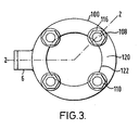
- the sealing arrangement 12 of Figure 2 is a section along the line 2-2 of Figure 3 .
- the anode connection member is ultimately connected to the anode 30 which is at least partially immersed in the electrolyte 18 as shown in Figure 1 , however, neither the anode nor its construction per se form any part of the invention and may be of any suitable construction or material according to the type of fluorine cell in which it is to be used.
- the anode connection member 32 (shown truncated in Figure 2 ) passes through an aperture 70 in the horizontal top plate 22 of the skirt member 20.
- connection member 32 is fixed to a skirt wall closure member 72 by means of screws 74 passing through holes 76 into threaded holes 78 in a boss 80 of the connection member 32, however, any means of connection of the member 32 to the closure member 72 may be employed.
- the arrangement described provides accuracy for the depending anode 30 in maintaining the anode 30 out of contact with the depending skirt wall member 24, but providing that accuracy can be assured, the connection member 30 may be welded, for example, to the underside 82 of the closure member 72.
- the end of the connection member 32 may be provided with a screw threaded male portion, for example, and screwed into a co-operating hole in the closure member 72, for example.
- the closure member 72 is insulated from the skirt 20 by a non-conductive annular spacer ring 90 which is positioned intermediate two annular gaskets 92.
- the gaskets 92 are spiral wound gaskets having inner keeper rings 94 and outer keeper rings 96. Whilst the gaskets 92 are electrically conductive they are separated by the non-conductive spacer ring 90 which, in this case, is made of non-porous alumina ceramic.
- the spacer ring 90 and gaskets 92 provide complete sealing against leakage of fluorine and the spacer ring 90 provides electrical insulation of the anode 30 from the skirt 20.
- auxiliary closure member 100 which is itself sealed to the closure member 72 by means of a further spiral wound gasket 102.
- a recess 104 is provided in the auxiliary closure member 100 to accommodate the heads of the screws 74.
- the auxiliary closure member 100, the closure member 72, the spacer ring 90, gaskets 92 and 102 are all held together by means of threaded studs 108 and nuts 110.
- the studs are insulated from the closure member 72 and auxiliary closure member 100 by insulating sleeves 112, in this case of Mylar (trade name) plastics material, extending along the length thereof and the nuts 110 are insulated from the auxiliary closure member top face 114 by insulating washers 116, in this case, of phenolic material such as Tufnol (trade name), for example.
- the spacer ring 90 and gaskets 92, 102 all lie within a pitch circle 120 defining the axes of the studs 108 and, of course, within a circle 122 defining the innermost extent of the stud 108 diameters thus, the insulating sleeves 112 and washers 116 are not subject to contact with fluorine.
- An electrical connector 56 is provided for a positive connection to the anode from a power source and controller (both not shown).
- the auxiliary closure member 100 is used due the fact that there are through holes 76 in the closure member 72 for the screws 74 securing the anode connection member 32 thereto and which could possibly be a source of fluorine leakage. However, if a construction is employed where no through holes are provided in the closure member 72 for securing the connection member 32 thereto, the auxiliary closure member 100 would not be required.
- One important advantage of the construction shown with reference to the Figures is that accurate angular location of the anode 30 within the skirt wall portion 24 is automatically achieved.
- spiral wound gaskets have been used to seal the faces of the spacer ring 90 and the corresponding faces of the skirt top plate, closure member and auxiliary closure member.
- the construction of such gaskets is well known in the prior art and they are particularly suitable when used in the present invention.
- spiral wound gaskets constructed with a dual winding of metal and polymer elements such as described hereinabove are used, only a very small end face area at the end of the wound gasket is potentially exposed to fluorine gas.
- keeper rings are employed even this area is substantially eliminated.
- other types of metal gaskets may be used such as embossed bead gaskets where beads are embossed into an essentially flat metal plate and sealing is achieved by compression of the beads by the tightening loads.
- the present invention effectively seals the fluorine compartment of the fluorine cell without the need to place large areas of polymer gasket materials in contact with fluorine and thus the risk of degradation causing fluorine leaks and the possibility of stud fires is greatly reduced compared with prior art sealing methods.
- the anode connection member 32 is further provided with a hole 130 to permit insertion of a retaining bar (not shown) therethrough for use when inspecting, servicing, replacing seals and the like or repairing the fluorine cell.
- a retaining bar (not shown) therethrough for use when inspecting, servicing, replacing seals and the like or repairing the fluorine cell.
- the anode connection member may be at least partially formed as an integral part of the closure member 72, e.g. as a spigot depending from the inner central part thereof and the anode joined thereto, for example, by an internally threaded collar co-operating with threaded ends on the anode connection portion at the upper end and a threaded end on a rod connected to an anode hanger at the lower end.
- the auxiliary closure member would not be required.
- the closure member and the anode connection member are a unitary item.
- Fluorine cells constructed according to the present invention have been found to have very high integrity against fluorine leaks and have leak tightness sufficient to pass a helium leak test at better than 10 -5 sccm (standard cubic centimetre min).
- seal members which may be employed in the present invention include but are not limited to: all metal seals such as ring joints made from steels, nickel, copper, copper-nickel alloys and aluminium; spiral wound joints using all metal windings; and, profile joints such as the bead type gaskets described hereinabove.
- part metal seals may be employed and may include but are not limited to: ring joints made from soft sealing materials where the sealing material is encapsulated in a groove or tongue and groove; spiral wound joints incorporating metal windings combined with soft sealing windings; and envelope joints comprising a metal envelope within which a filler material is encapsulated.
Landscapes
- Chemical & Material Sciences (AREA)
- Engineering & Computer Science (AREA)
- Chemical Kinetics & Catalysis (AREA)
- Electrochemistry (AREA)
- Materials Engineering (AREA)
- Metallurgy (AREA)
- Organic Chemistry (AREA)
- Inorganic Chemistry (AREA)
- Electrolytic Production Of Non-Metals, Compounds, Apparatuses Therefor (AREA)
- Gasket Seals (AREA)
Claims (14)
- Fluor-Elektrolytzelle (10), umfassend:ein Anodenanschlussstück (32) mit Endstück;eine Sockelleistenstruktur (20) mit Kopfplatte (22), wobei die Kopfplatte eine Öffnung (70) hat und das Anodenanschlussstück durch die Öffnung hindurchgeht;ein Schließelement (72) für die Sockelleistenkopfplatte, das dicht mit der Sockelleistenkopfplatte abschließt, wobei das Schließelement für die Sockelleistenkopfplatte einen elektrischen Anschluss an das Anodenanschlussstück hat, so dass sich in der Fluorzelle eine Anodenverbindung (56) ergibt; undein nicht-leitender Abstandshalter (90), der sich zur Abdichtung zwischen dem Schließelement für die Sockelleistenkopfplatte und der Außenfläche der Sockelleistenkopfplatte befindet, wobei das Endstück des Anodenanschlussstücks durch das Schließelement für die Sockelleistenkopfplatte fixiert ist, wobei das Endstück des Anodenanschlussstücks von der Sockelleistenkopfplatte und der Öffnung durch den Abstandshalter und das Schließelement für die Sockelleistenkopfplatte räumlich getrennt ist.
- Fluor-Elektrolytzelle nach Anspruch 1, wobei der Abstandshalter aus Keramik inklusive entweder Aluminiumoxid, Kalziumfluorid oder Magnesiumfluorid besteht.
- Fluor-Elektrolytzelle nach Anspruch 1, wobei der Abstandshalter ringförmig um das Anodenanschlussstück geformt ist.
- Fluor-Elektrolytzelle nach Anspruch 1, wobei der Abstandshalter zwischen Dichtungen (92) eingeschlossen ist, die zwischen der Oberseite der Sockelleistenkopfplatte und der Unterseite des Abstandshalters und der Oberseite des Abstandshalters und der Unterseite des Schließelements der Sockelleistenkopfplatte abdichten.
- Fluor-Elektrolytzelle nach Anspruch 4, wobei die Dichtungen spiralförmig gewickelte Dichtungen sind.
- Fluor-Elektrolytzelle nach Anspruch 5, wobei die spiralförmig gewickelten Dichtungen mindestens einen inneren Haltering (94) umfassen.
- Fluor-Elektrolytzelle nach Anspruch 5, wobei die spiralförmig gewickelten Dichtungen mindestens einen äußeren Haltering (96) umfassen.
- Fluor-Elektrolytzelle nach Anspruch 4, wobei die Dichtungen Metallranddichtungen sind.
- Fluor-Elektrolytzelle nach Anspruch 8, wobei die Metallranddichtungen eine Metallplatte mit eingestanztem Rand umfassen.
- Fluor-Elektrolytzelle nach Anspruch 1, wobei das Endstück des Anodenanschlussstücks am Schließelement für die Sockelleistenkopfplatte angeschweißt ist.
- Fluor-Elektrolytzelle nach Anspruch 1, wobei das Endstück des Anodenanschlussstücks mit einem mechanischen Verschluss am Schließelement für die Sockelleistenkopfplatte befestigt ist.
- Fluor-Elektrolytzelle nach Anspruch 11, außerdem umfassend ein zusätzliches Schließelement (100).
- Fluor-Elektrolytzelle nach Anspruch 12, wobei das zusätzliche Schließelement mit dem Schließelement für die Sockelleistenkopfplatte über eine weitere Dichtung, die die Halterung des Anodenanschlussstücks umgibt, dicht im Eingriff ist.
- Verfahren zum Einsetzen einer Anode in eine Elektrolytzelle zur Herstellung von Fluor (10), das folgende Schritte umfasst:Bereitstellung einer Sockelleistenstruktur (20) für die Elektrolytzelle zur Herstellung von Fluor, wobei die Sockelleiste eine offene Konstruktion mit einem niedrigeren Endpunkt hat, der in einen Elektrolyt eingetaucht ist und ein geschlossenes Volumen formt;Ausprägung einer Öffnung (70) in der Kopfplatte (22) der Sockelleistenstruktur zum Durchführen eines Anodenanschlussstücks (32);Abhängung des Anodenanschlussstücks vom Schließelement (72) der Sockelleistenkopfplatte und Abdichtung dieser Öffnung mit dem Schließelement der Sockelleiste durch Bereitstellung von mindestens einem nicht elektrisch leitendenden Abstandshalter (90) dazwischen, wobei das Endstück des Anodenanschlussstücks durch das Schließelement für die Sockelleistenkopfplatte fixiert wird, wobei das Endstück des Anodenanschlussstücks von der Sockelleistenkopfplatte und der Öffnung durch mindestens einen Abstandshalter und ein Schließelement für die Sockelleistenkopfplatte räumlich getrennt ist.
Applications Claiming Priority (3)
| Application Number | Priority Date | Filing Date | Title |
|---|---|---|---|
| GBGB0215697.4A GB0215697D0 (en) | 2002-07-06 | 2002-07-06 | Fluorine cell |
| GB0215697 | 2002-07-06 | ||
| PCT/GB2003/002758 WO2004005584A1 (en) | 2002-07-06 | 2003-06-27 | Fluorine cell |
Publications (2)
| Publication Number | Publication Date |
|---|---|
| EP1527210A1 EP1527210A1 (de) | 2005-05-04 |
| EP1527210B1 true EP1527210B1 (de) | 2015-10-07 |
Family
ID=9939979
Family Applications (1)
| Application Number | Title | Priority Date | Filing Date |
|---|---|---|---|
| EP03762759.3A Expired - Lifetime EP1527210B1 (de) | 2002-07-06 | 2003-06-27 | Fluor-zelle |
Country Status (9)
| Country | Link |
|---|---|
| US (1) | US7481911B2 (de) |
| EP (1) | EP1527210B1 (de) |
| JP (1) | JP4530850B2 (de) |
| KR (1) | KR101089471B1 (de) |
| CN (1) | CN100351432C (de) |
| AU (1) | AU2003251134A1 (de) |
| GB (1) | GB0215697D0 (de) |
| TW (1) | TWI314956B (de) |
| WO (1) | WO2004005584A1 (de) |
Families Citing this family (3)
| Publication number | Priority date | Publication date | Assignee | Title |
|---|---|---|---|---|
| CN101949025A (zh) * | 2010-10-18 | 2011-01-19 | 天津市泰旭物流有限公司 | 一种采用电解合成法生产六氟化硫的技术 |
| BR102013017403A2 (pt) * | 2013-07-05 | 2016-07-12 | Charles Adriano Duvoisin | equipamento compacto para esterilização por eletrólise de alimentos e utensílios |
| EP3647467B1 (de) | 2017-06-30 | 2022-04-06 | Showa Denko K.K. | Anodenmontageelement einer fluorelektrolysezelle, fluorelektrolysezelle und verfahren zur herstellung von fluorgas |
Family Cites Families (14)
| Publication number | Priority date | Publication date | Assignee | Title |
|---|---|---|---|---|
| US2739115A (en) * | 1952-06-19 | 1956-03-20 | Pennsylvania Salt Mfg Co | Fluorine cell |
| NL170314C (nl) | 1970-06-01 | 1982-10-18 | Montedison Spa | Electrolysecel voor de bereiding van fluor. |
| JPS552027Y2 (de) * | 1975-12-26 | 1980-01-19 | ||
| JPS5715261Y2 (de) * | 1978-11-18 | 1982-03-30 | ||
| US4354916A (en) * | 1981-05-04 | 1982-10-19 | Diamond Shamrock Corporation | High current density electrical contact device |
| US4544078A (en) * | 1984-05-22 | 1985-10-01 | Cordis Corporation | Sealed closure for sealing and closing an opening in a container |
| CN85108000A (zh) * | 1984-09-24 | 1987-04-01 | 陶氏化学公司 | 电解槽的密封 |
| US5203397A (en) * | 1992-04-02 | 1993-04-20 | Hotset Corporation | Heating assembly for a die-casting machine |
| GB9418598D0 (en) * | 1994-09-14 | 1994-11-02 | British Nuclear Fuels Plc | Fluorine cell |
| DE19704515C2 (de) | 1997-02-06 | 2002-02-21 | Andreas Stadlbauer | Mechanische Tiernachbildung |
| GB9725067D0 (en) * | 1997-11-28 | 1998-01-28 | Fluorogas Limited | Fluorine cell |
| US6210549B1 (en) * | 1998-11-13 | 2001-04-03 | Larry A. Tharp | Fluorine gas generation system |
| CN2434312Y (zh) * | 2000-08-14 | 2001-06-13 | 高大明 | 电解槽 |
| JP3642023B2 (ja) * | 2000-11-22 | 2005-04-27 | 昭和電工株式会社 | フッ素電解槽陽極取付部、フッ素電解槽及びフッ素ガスの製造方法 |
-
2002
- 2002-07-06 GB GBGB0215697.4A patent/GB0215697D0/en not_active Ceased
-
2003
- 2003-06-27 AU AU2003251134A patent/AU2003251134A1/en not_active Abandoned
- 2003-06-27 EP EP03762759.3A patent/EP1527210B1/de not_active Expired - Lifetime
- 2003-06-27 KR KR1020047019612A patent/KR101089471B1/ko not_active Expired - Lifetime
- 2003-06-27 WO PCT/GB2003/002758 patent/WO2004005584A1/en not_active Ceased
- 2003-06-27 JP JP2004518916A patent/JP4530850B2/ja not_active Expired - Lifetime
- 2003-06-27 US US10/520,501 patent/US7481911B2/en not_active Expired - Fee Related
- 2003-06-27 CN CNB038160056A patent/CN100351432C/zh not_active Expired - Lifetime
- 2003-06-30 TW TW092117804A patent/TWI314956B/zh not_active IP Right Cessation
Also Published As
| Publication number | Publication date |
|---|---|
| US20060113186A1 (en) | 2006-06-01 |
| TWI314956B (en) | 2009-09-21 |
| EP1527210A1 (de) | 2005-05-04 |
| CN100351432C (zh) | 2007-11-28 |
| KR20050027989A (ko) | 2005-03-21 |
| TW200401847A (en) | 2004-02-01 |
| KR101089471B1 (ko) | 2011-12-07 |
| GB0215697D0 (en) | 2002-08-14 |
| JP2005532475A (ja) | 2005-10-27 |
| JP4530850B2 (ja) | 2010-08-25 |
| AU2003251134A1 (en) | 2004-01-23 |
| US7481911B2 (en) | 2009-01-27 |
| CN1665962A (zh) | 2005-09-07 |
| WO2004005584A1 (en) | 2004-01-15 |
Similar Documents
| Publication | Publication Date | Title |
|---|---|---|
| US11283098B2 (en) | System for high-temperature tight coupling of a stack having SOEC/SOFC-type solid oxides | |
| JP7601636B2 (ja) | Soec/sofc型固体酸化物スタック、圧着システム、および熱交換システムを備えるアセンブリ | |
| EP0137836A1 (de) | Zentrales einheitszellelement für filterpresse-elektrolysezellstruktur. | |
| US20250043440A1 (en) | Electrolysis cell with a cell casing made from metal foil and electrolyzer | |
| JP5258541B2 (ja) | 結晶成長炉における電極固着構造体 | |
| EP1527210B1 (de) | Fluor-zelle | |
| US12264397B2 (en) | Assembly comprising a SOEC/SOFC-type solid oxide stack and a high-temperature sealed coupling system | |
| US4673479A (en) | Fabricated electrochemical cell | |
| CA1141333A (en) | Method and apparatus for installation of a membrane to an electrolytic cell | |
| JPS61502967A (ja) | 完全組立電気化学槽 | |
| US6200438B1 (en) | Cell cover for electrolytic cells | |
| EP1230434B1 (de) | Verbesserter entwurf für diaphragmaelektrolyseur | |
| US4051008A (en) | Flanged connection means for anode posts in electrolytic diaphragm cells | |
| NZ238898A (en) | Multi-cell electrolyser | |
| HK1025366A (en) | Cell cover for electrolytic cells | |
| CN1243553A (zh) | 用于电解槽的槽盖 | |
| MXPA02004576A (en) | Improved design of diaphragm electrolyser |
Legal Events
| Date | Code | Title | Description |
|---|---|---|---|
| PUAI | Public reference made under article 153(3) epc to a published international application that has entered the european phase |
Free format text: ORIGINAL CODE: 0009012 |
|
| 17P | Request for examination filed |
Effective date: 20041104 |
|
| AK | Designated contracting states |
Kind code of ref document: A1 Designated state(s): AT BE BG CH CY CZ DE DK EE ES FI FR GB GR HU IE IT LI LU MC NL PT RO SE SI SK TR |
|
| AX | Request for extension of the european patent |
Extension state: AL LT LV MK |
|
| DAX | Request for extension of the european patent (deleted) | ||
| RAP1 | Party data changed (applicant data changed or rights of an application transferred) |
Owner name: THE BOC GROUP LIMITED |
|
| 17Q | First examination report despatched |
Effective date: 20130422 |
|
| REG | Reference to a national code |
Ref country code: DE Ref legal event code: R079 Ref document number: 60348121 Country of ref document: DE Free format text: PREVIOUS MAIN CLASS: C25B0009020000 Ipc: C25B0001240000 |
|
| GRAP | Despatch of communication of intention to grant a patent |
Free format text: ORIGINAL CODE: EPIDOSNIGR1 |
|
| RIC1 | Information provided on ipc code assigned before grant |
Ipc: C25B 1/24 20060101AFI20150330BHEP Ipc: C25B 9/02 20060101ALI20150330BHEP |
|
| INTG | Intention to grant announced |
Effective date: 20150429 |
|
| GRAS | Grant fee paid |
Free format text: ORIGINAL CODE: EPIDOSNIGR3 |
|
| GRAA | (expected) grant |
Free format text: ORIGINAL CODE: 0009210 |
|
| AK | Designated contracting states |
Kind code of ref document: B1 Designated state(s): AT BE BG CH CY CZ DE DK EE ES FI FR GB GR HU IE IT LI LU MC NL PT RO SE SI SK TR |
|
| REG | Reference to a national code |
Ref country code: GB Ref legal event code: FG4D |
|
| REG | Reference to a national code |
Ref country code: AT Ref legal event code: REF Ref document number: 753815 Country of ref document: AT Kind code of ref document: T Effective date: 20151015 Ref country code: CH Ref legal event code: EP |
|
| REG | Reference to a national code |
Ref country code: IE Ref legal event code: FG4D |
|
| REG | Reference to a national code |
Ref country code: DE Ref legal event code: R096 Ref document number: 60348121 Country of ref document: DE |
|
| REG | Reference to a national code |
Ref country code: NL Ref legal event code: MP Effective date: 20151007 |
|
| REG | Reference to a national code |
Ref country code: AT Ref legal event code: MK05 Ref document number: 753815 Country of ref document: AT Kind code of ref document: T Effective date: 20151007 |
|
| PG25 | Lapsed in a contracting state [announced via postgrant information from national office to epo] |
Ref country code: NL Free format text: LAPSE BECAUSE OF FAILURE TO SUBMIT A TRANSLATION OF THE DESCRIPTION OR TO PAY THE FEE WITHIN THE PRESCRIBED TIME-LIMIT Effective date: 20151007 Ref country code: ES Free format text: LAPSE BECAUSE OF FAILURE TO SUBMIT A TRANSLATION OF THE DESCRIPTION OR TO PAY THE FEE WITHIN THE PRESCRIBED TIME-LIMIT Effective date: 20151007 |
|
| REG | Reference to a national code |
Ref country code: FR Ref legal event code: PLFP Year of fee payment: 14 |
|
| PG25 | Lapsed in a contracting state [announced via postgrant information from national office to epo] |
Ref country code: FI Free format text: LAPSE BECAUSE OF FAILURE TO SUBMIT A TRANSLATION OF THE DESCRIPTION OR TO PAY THE FEE WITHIN THE PRESCRIBED TIME-LIMIT Effective date: 20151007 Ref country code: AT Free format text: LAPSE BECAUSE OF FAILURE TO SUBMIT A TRANSLATION OF THE DESCRIPTION OR TO PAY THE FEE WITHIN THE PRESCRIBED TIME-LIMIT Effective date: 20151007 Ref country code: GR Free format text: LAPSE BECAUSE OF FAILURE TO SUBMIT A TRANSLATION OF THE DESCRIPTION OR TO PAY THE FEE WITHIN THE PRESCRIBED TIME-LIMIT Effective date: 20160108 Ref country code: SE Free format text: LAPSE BECAUSE OF FAILURE TO SUBMIT A TRANSLATION OF THE DESCRIPTION OR TO PAY THE FEE WITHIN THE PRESCRIBED TIME-LIMIT Effective date: 20151007 Ref country code: PT Free format text: LAPSE BECAUSE OF FAILURE TO SUBMIT A TRANSLATION OF THE DESCRIPTION OR TO PAY THE FEE WITHIN THE PRESCRIBED TIME-LIMIT Effective date: 20160208 |
|
| REG | Reference to a national code |
Ref country code: DE Ref legal event code: R097 Ref document number: 60348121 Country of ref document: DE |
|
| PG25 | Lapsed in a contracting state [announced via postgrant information from national office to epo] |
Ref country code: CZ Free format text: LAPSE BECAUSE OF FAILURE TO SUBMIT A TRANSLATION OF THE DESCRIPTION OR TO PAY THE FEE WITHIN THE PRESCRIBED TIME-LIMIT Effective date: 20151007 |
|
| PLBE | No opposition filed within time limit |
Free format text: ORIGINAL CODE: 0009261 |
|
| STAA | Information on the status of an ep patent application or granted ep patent |
Free format text: STATUS: NO OPPOSITION FILED WITHIN TIME LIMIT |
|
| PG25 | Lapsed in a contracting state [announced via postgrant information from national office to epo] |
Ref country code: SK Free format text: LAPSE BECAUSE OF FAILURE TO SUBMIT A TRANSLATION OF THE DESCRIPTION OR TO PAY THE FEE WITHIN THE PRESCRIBED TIME-LIMIT Effective date: 20151007 Ref country code: RO Free format text: LAPSE BECAUSE OF FAILURE TO SUBMIT A TRANSLATION OF THE DESCRIPTION OR TO PAY THE FEE WITHIN THE PRESCRIBED TIME-LIMIT Effective date: 20151007 Ref country code: DK Free format text: LAPSE BECAUSE OF FAILURE TO SUBMIT A TRANSLATION OF THE DESCRIPTION OR TO PAY THE FEE WITHIN THE PRESCRIBED TIME-LIMIT Effective date: 20151007 Ref country code: EE Free format text: LAPSE BECAUSE OF FAILURE TO SUBMIT A TRANSLATION OF THE DESCRIPTION OR TO PAY THE FEE WITHIN THE PRESCRIBED TIME-LIMIT Effective date: 20151007 |
|
| 26N | No opposition filed |
Effective date: 20160708 |
|
| PG25 | Lapsed in a contracting state [announced via postgrant information from national office to epo] |
Ref country code: SI Free format text: LAPSE BECAUSE OF FAILURE TO SUBMIT A TRANSLATION OF THE DESCRIPTION OR TO PAY THE FEE WITHIN THE PRESCRIBED TIME-LIMIT Effective date: 20151007 |
|
| PG25 | Lapsed in a contracting state [announced via postgrant information from national office to epo] |
Ref country code: BE Free format text: LAPSE BECAUSE OF FAILURE TO SUBMIT A TRANSLATION OF THE DESCRIPTION OR TO PAY THE FEE WITHIN THE PRESCRIBED TIME-LIMIT Effective date: 20151007 |
|
| PG25 | Lapsed in a contracting state [announced via postgrant information from national office to epo] |
Ref country code: MC Free format text: LAPSE BECAUSE OF FAILURE TO SUBMIT A TRANSLATION OF THE DESCRIPTION OR TO PAY THE FEE WITHIN THE PRESCRIBED TIME-LIMIT Effective date: 20151007 |
|
| REG | Reference to a national code |
Ref country code: CH Ref legal event code: PL |
|
| REG | Reference to a national code |
Ref country code: IE Ref legal event code: MM4A |
|
| PG25 | Lapsed in a contracting state [announced via postgrant information from national office to epo] |
Ref country code: LI Free format text: LAPSE BECAUSE OF NON-PAYMENT OF DUE FEES Effective date: 20160630 Ref country code: CH Free format text: LAPSE BECAUSE OF NON-PAYMENT OF DUE FEES Effective date: 20160630 |
|
| REG | Reference to a national code |
Ref country code: FR Ref legal event code: PLFP Year of fee payment: 15 |
|
| PG25 | Lapsed in a contracting state [announced via postgrant information from national office to epo] |
Ref country code: IE Free format text: LAPSE BECAUSE OF NON-PAYMENT OF DUE FEES Effective date: 20160627 |
|
| REG | Reference to a national code |
Ref country code: FR Ref legal event code: PLFP Year of fee payment: 16 |
|
| PG25 | Lapsed in a contracting state [announced via postgrant information from national office to epo] |
Ref country code: CY Free format text: LAPSE BECAUSE OF FAILURE TO SUBMIT A TRANSLATION OF THE DESCRIPTION OR TO PAY THE FEE WITHIN THE PRESCRIBED TIME-LIMIT Effective date: 20151007 Ref country code: HU Free format text: LAPSE BECAUSE OF FAILURE TO SUBMIT A TRANSLATION OF THE DESCRIPTION OR TO PAY THE FEE WITHIN THE PRESCRIBED TIME-LIMIT; INVALID AB INITIO Effective date: 20030627 |
|
| PG25 | Lapsed in a contracting state [announced via postgrant information from national office to epo] |
Ref country code: TR Free format text: LAPSE BECAUSE OF FAILURE TO SUBMIT A TRANSLATION OF THE DESCRIPTION OR TO PAY THE FEE WITHIN THE PRESCRIBED TIME-LIMIT Effective date: 20151007 Ref country code: LU Free format text: LAPSE BECAUSE OF NON-PAYMENT OF DUE FEES Effective date: 20160627 |
|
| PG25 | Lapsed in a contracting state [announced via postgrant information from national office to epo] |
Ref country code: BG Free format text: LAPSE BECAUSE OF FAILURE TO SUBMIT A TRANSLATION OF THE DESCRIPTION OR TO PAY THE FEE WITHIN THE PRESCRIBED TIME-LIMIT Effective date: 20151007 |
|
| PGFP | Annual fee paid to national office [announced via postgrant information from national office to epo] |
Ref country code: DE Payment date: 20190612 Year of fee payment: 17 Ref country code: IT Payment date: 20190620 Year of fee payment: 17 |
|
| PGFP | Annual fee paid to national office [announced via postgrant information from national office to epo] |
Ref country code: FR Payment date: 20190510 Year of fee payment: 17 |
|
| PGFP | Annual fee paid to national office [announced via postgrant information from national office to epo] |
Ref country code: GB Payment date: 20190626 Year of fee payment: 17 |
|
| REG | Reference to a national code |
Ref country code: DE Ref legal event code: R119 Ref document number: 60348121 Country of ref document: DE |
|
| GBPC | Gb: european patent ceased through non-payment of renewal fee |
Effective date: 20200627 |
|
| PG25 | Lapsed in a contracting state [announced via postgrant information from national office to epo] |
Ref country code: GB Free format text: LAPSE BECAUSE OF NON-PAYMENT OF DUE FEES Effective date: 20200627 Ref country code: FR Free format text: LAPSE BECAUSE OF NON-PAYMENT OF DUE FEES Effective date: 20200630 |
|
| PG25 | Lapsed in a contracting state [announced via postgrant information from national office to epo] |
Ref country code: DE Free format text: LAPSE BECAUSE OF NON-PAYMENT OF DUE FEES Effective date: 20210101 |
|
| PG25 | Lapsed in a contracting state [announced via postgrant information from national office to epo] |
Ref country code: IT Free format text: LAPSE BECAUSE OF NON-PAYMENT OF DUE FEES Effective date: 20200627 |