EP1526607A1 - Connector assuring more reliability - Google Patents
Connector assuring more reliability Download PDFInfo
- Publication number
- EP1526607A1 EP1526607A1 EP04025176A EP04025176A EP1526607A1 EP 1526607 A1 EP1526607 A1 EP 1526607A1 EP 04025176 A EP04025176 A EP 04025176A EP 04025176 A EP04025176 A EP 04025176A EP 1526607 A1 EP1526607 A1 EP 1526607A1
- Authority
- EP
- European Patent Office
- Prior art keywords
- housing
- contact
- insulation displacement
- cable
- connector
- Prior art date
- Legal status (The legal status is an assumption and is not a legal conclusion. Google has not performed a legal analysis and makes no representation as to the accuracy of the status listed.)
- Granted
Links
Images




Classifications
-
- H—ELECTRICITY
- H01—ELECTRIC ELEMENTS
- H01R—ELECTRICALLY-CONDUCTIVE CONNECTIONS; STRUCTURAL ASSOCIATIONS OF A PLURALITY OF MUTUALLY-INSULATED ELECTRICAL CONNECTING ELEMENTS; COUPLING DEVICES; CURRENT COLLECTORS
- H01R4/00—Electrically-conductive connections between two or more conductive members in direct contact, i.e. touching one another; Means for effecting or maintaining such contact; Electrically-conductive connections having two or more spaced connecting locations for conductors and using contact members penetrating insulation
- H01R4/24—Connections using contact members penetrating or cutting insulation or cable strands
- H01R4/2416—Connections using contact members penetrating or cutting insulation or cable strands the contact members having insulation-cutting edges, e.g. of tuning fork type
- H01R4/242—Connections using contact members penetrating or cutting insulation or cable strands the contact members having insulation-cutting edges, e.g. of tuning fork type the contact members being plates having a single slot
- H01R4/2425—Flat plates, e.g. multi-layered flat plates
- H01R4/2429—Flat plates, e.g. multi-layered flat plates mounted in an insulating base
- H01R4/2433—Flat plates, e.g. multi-layered flat plates mounted in an insulating base one part of the base being movable to push the cable into the slot
-
- H—ELECTRICITY
- H01—ELECTRIC ELEMENTS
- H01R—ELECTRICALLY-CONDUCTIVE CONNECTIONS; STRUCTURAL ASSOCIATIONS OF A PLURALITY OF MUTUALLY-INSULATED ELECTRICAL CONNECTING ELEMENTS; COUPLING DEVICES; CURRENT COLLECTORS
- H01R12/00—Structural associations of a plurality of mutually-insulated electrical connecting elements, specially adapted for printed circuits, e.g. printed circuit boards [PCB], flat or ribbon cables, or like generally planar structures, e.g. terminal strips, terminal blocks; Coupling devices specially adapted for printed circuits, flat or ribbon cables, or like generally planar structures; Terminals specially adapted for contact with, or insertion into, printed circuits, flat or ribbon cables, or like generally planar structures
- H01R12/70—Coupling devices
-
- H—ELECTRICITY
- H01—ELECTRIC ELEMENTS
- H01R—ELECTRICALLY-CONDUCTIVE CONNECTIONS; STRUCTURAL ASSOCIATIONS OF A PLURALITY OF MUTUALLY-INSULATED ELECTRICAL CONNECTING ELEMENTS; COUPLING DEVICES; CURRENT COLLECTORS
- H01R12/00—Structural associations of a plurality of mutually-insulated electrical connecting elements, specially adapted for printed circuits, e.g. printed circuit boards [PCB], flat or ribbon cables, or like generally planar structures, e.g. terminal strips, terminal blocks; Coupling devices specially adapted for printed circuits, flat or ribbon cables, or like generally planar structures; Terminals specially adapted for contact with, or insertion into, printed circuits, flat or ribbon cables, or like generally planar structures
- H01R12/50—Fixed connections
- H01R12/59—Fixed connections for flexible printed circuits, flat or ribbon cables or like structures
- H01R12/594—Fixed connections for flexible printed circuits, flat or ribbon cables or like structures for shielded flat cable
- H01R12/598—Each conductor being individually surrounded by shield, e.g. multiple coaxial cables in flat structure
-
- H—ELECTRICITY
- H01—ELECTRIC ELEMENTS
- H01R—ELECTRICALLY-CONDUCTIVE CONNECTIONS; STRUCTURAL ASSOCIATIONS OF A PLURALITY OF MUTUALLY-INSULATED ELECTRICAL CONNECTING ELEMENTS; COUPLING DEVICES; CURRENT COLLECTORS
- H01R12/00—Structural associations of a plurality of mutually-insulated electrical connecting elements, specially adapted for printed circuits, e.g. printed circuit boards [PCB], flat or ribbon cables, or like generally planar structures, e.g. terminal strips, terminal blocks; Coupling devices specially adapted for printed circuits, flat or ribbon cables, or like generally planar structures; Terminals specially adapted for contact with, or insertion into, printed circuits, flat or ribbon cables, or like generally planar structures
- H01R12/50—Fixed connections
- H01R12/59—Fixed connections for flexible printed circuits, flat or ribbon cables or like structures
- H01R12/65—Fixed connections for flexible printed circuits, flat or ribbon cables or like structures characterised by the terminal
- H01R12/67—Fixed connections for flexible printed circuits, flat or ribbon cables or like structures characterised by the terminal insulation penetrating terminals
-
- H—ELECTRICITY
- H01—ELECTRIC ELEMENTS
- H01R—ELECTRICALLY-CONDUCTIVE CONNECTIONS; STRUCTURAL ASSOCIATIONS OF A PLURALITY OF MUTUALLY-INSULATED ELECTRICAL CONNECTING ELEMENTS; COUPLING DEVICES; CURRENT COLLECTORS
- H01R4/00—Electrically-conductive connections between two or more conductive members in direct contact, i.e. touching one another; Means for effecting or maintaining such contact; Electrically-conductive connections having two or more spaced connecting locations for conductors and using contact members penetrating insulation
- H01R4/24—Connections using contact members penetrating or cutting insulation or cable strands
Definitions
- This invention relates to a connector to be connected to any kind of cables including a coaxial cable and a thin cable.
- a connector of the type is disclosed, for example, in Japanese Patent Application Publication (JP-A) No. H11-345640.
- the connector comprises a housing, a plurality of contacts held by the housing, and a movable operating lever.
- the cables are positioned to face the contacts. Thereafter, when the operating lever is operated, the cables are pressed against the contacts by a pressing portion as a part of the operating lever. Thus, the connector is connected to the cables.
- the connector of the type is also disclosed, for example, in Japanese Patent Application Publications (JP-A) Nos. H11-317248 and 2000-260497.
- IDC insulation displacement connection
- a connector to be connected to a cable by an insulation displacement connection comprising a first housing having a holding portion for receiving the cable, a contact to be contacted with a mating connector, and a second housing holding the contact and coupled to the first housing with its rotation with respect to the first housing, the contact having a pair of insulation displacement portions faced to each other with a gap and adapted to be connected to the cable by the insulation displacement connection, the holding portion being inserted into the gap following the rotation of the second housing so that the cable is clamped between each of the insulation displacement portions and the holding portion.
- the connector uses an insulation displacement connection technology, it will hereinafter be called an "insulation displacement connector”.
- the Insulation displacement connector comprises a first housing 1 made of synthetic resin.
- the first housing 1 is provided with a plurality of grooves 1a formed at a left lower half portion thereof to receive a plurality of coaxial cables 11, respectively, and a protruding guide portion 1b having a generally triangular shape.
- the grooves 1a are formed at a predetermined pitch in a predetermined direction, i.e., a direction perpendicular to a drawing sheet.
- the first housing 1 has, at a right half portion, a space 1c and a plurality of grooves 1d both for receiving the coaxial cables 11, and a protruding guide portion 1e having a generally rectangular shape and serving as a holding portion.
- Each of the coaxial cables 11 comprises a conductive core wire 11 a coated with a dielectric member 11 b and a grounding external conductor 11c successively formed around the core wire 11a. Prior to connection to the Insulation displacement connector, the external conductor 11c at an end of each coaxial cable 11 is peeled off and removed.
- each of the coaxial cables 11 is press-fitted into the grooves 1 b and 1 d and arranged along the protruding guide portions 1b and 1e. Then, the state illustrated in Fig. 1 B is reached. In this state, each coaxial cable 11 is applied with tension. Since the coaxial cable 11 is held in the groove 1d on the protruding guide portion 1e, the coaxial cable 11 is stable held in the first housing 1.
- the Insulation displacement connector further comprises a second housing 6 made of synthetic resin and a plurality of conductive contacts 7 held by the second housing 6 and arranged at a predetermined pitch in the predetermined direction.
- the second housing 6 is provided with a plurality of press-fit grooves 6a and 6b formed at a predetermined pitch in a direction perpendicular to the drawing sheet to hold the contacts 7, and a pivot point portion 6c serving as a pivot point or center of rotation when the second housing 6 is rotated with respect to the first housing 1.
- Each contact 7 has a pair of connection terminal portions 7a and 7b, a fixing portion 7c, and a press-contacting terminal portion 7d.
- the press-contacting terminal portion 7d is provided with a pair of first and second blade shape portions 7d1 and 7d2 faced to each other with a gap.
- the first and the second blade shape portions 7d1 and 7d2 are referred to as press-contacting portions or insulation displacement contact portions, respectively.
- the connection terminal portion 7b and the fixing portion 7c of each contact 7 are press-fitted into the press-fit grooves 6a and 6b of the second housing 6, respectively.
- the second housing 6 is inserted into the first housing 1 in an inclined position.
- the second housing 6 is rotated clockwise around the pivot point portion 6c (herein, the pivot point portion 6c is slightly moved during rotation).
- the pivot point portion 6c is butted against a protruding support portion 1f of the first housing 1 and the second housing 6 is rotatably moved through the state illustrated in Fig. 2B to the state illustrated in Fig. 3.
- the protruding guide portion 1e is inserted into the gap between the first and the second blade shape portions 7d1 and 7d2 so that the cable 11 is clamped between each of the first and the second blade shape portions 7d1 and 7d2 and the protruding guide portion 1e.
- each contact 7 is electrically connected to each coaxial cable 11 by using a press-fitting technology which is similar to an insulation displacement connection (IDC) known in the art and therefore will also be called herein an insulation displacement connection.
- IDC insulation displacement connection
- the blade shape portions 7d1 and 7d2 easily break the dielectric member 11 b of the coaxial cable 11 and clamp both of the protruding guide portion or holding portion 1e of the first housing 1 and the coaxial cable 11. Because mutual contact is established by the insulation displacement contact portions (7d1, 7d2), the contact 7 is reliably connected to the coaxial cable 11. Since the contact 7 is connected to the coaxial cable 11 at two positions, connection is more reliable. Thereafter, the connection terminal portions 7a and 7b of the Insulation displacement connector are connected to corresponding connection terminal portions of a mating connector (not shown).
- the Insulation displacement connector further comprises a conductive ground bar 8 held by the first housing 1.
- the ground bar 8 has a pair of side portions 8a and a coupling portion 8b in the shape of a rectangular frame coupling the side portions 8a to each other.
- Each of the side portions 8a has an integral structure including a press-fit portion 8a1, a first linear coupling portion 8a2, a U-shaped portion 8a3, and a second linear coupling portion 8a4, and a L-shaped portion 8a5.
- the ground bar 8 is attached to the first housing 1 in the following manner.
- the press-fit portion 8a1 of each side portion 8a is press-fitted into each groove (not shown) formed on the first housing 1.
- the U-shaped portion 8a3 and the L-shaped portion 8a5 are inserted into grooves 1 g and 1 h formed on the first housing 1, respectively.
- each side portion 8a is put into the state illustrated in Fig. 4B.
- an upper surface of the coupling portion 8b of the ground bar 8 and the external conductor 11c of each coaxial cable 11 are soldered.
- the second housing 6 is inserted into the first housing 1 in an inclined position as illustrated in Fig. 5A and is rotated with respect to the first housing 1 to the state illustrated in Fig. 5B. Then, the first blade shape portions 7d1 of the contacts 7 arranged at opposite ends in the predetermined direction bite into the L-shaped portion 8a5 of the ground bar 8. Thus, a ground structure is formed.
- each contact 7 is electrically connected to each coaxial cable 11.
- FIG. 6A, 6B, 7A, 7B, and 8 description will be made of an Insulation displacement connector according to a third embodiment of the present invention. Similar parts are designated by like reference numerals and description thereof will be omitted.
- the first housing 1 has a protruding support portion 1 i which protrudes relatively high.
- Each contact 7 is provided with a disengagement-prevention protruding portion 7d3 formed on a side opposite to the first blade shape portion 7d1 of the insulation displacement terminal portion 7d.
- the second housing 6 is inserted into the first housing 1 in an inclined position as illustrated in Fig. 7A and rotated with respect to the first housing 1 to the state illustrated in Fig. 8. Then, the first and the second blade shape portions 7d1 and 7d2 of each contact 7 break the dielectric member 11b of each coaxial cable 11 to be press-contacted with the core wire 11a. As a result, the first and the second blade shape portions 7d1 and 7d2 clamp both of the protruding guide portion 1e of the first housing 1 and the coaxial cable 11. Thus, each contact 7 is electrically connected to each coaxial cable 11.
- the disengagement-prevention protruding portion 7d3 is butted against the protruding support portion 1f and is prevented from being disengaged from the protruding support portion 1f.
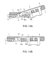
- FIGs. 9, 9A, 9B, 10A, and 10B description will be made of an Insulation displacement connector according to a fourth embodiment of the present invention. Similar parts are designated by like reference numerals and description thereof will be omitted.
- the first housing 1 has the protruding support portion 1i and the contact 7 has the disengagement-prevention protruding portion 7d3.
- the second housing 6 is inserted into the first housing 1 in an inclined portion as illustrated in Fig. 10A and rotated with respect to the first housing 1 to the state illustrated in Fig. 10B. Then, the first blade shape portions 7d1 of the contacts 7 arranged at opposite ends in the predetermined direction bite into the L-shaped portion 8a5 of the ground bar 8. Thus, a ground structure is formed.
- each contact 7 is electrically connected to each coaxial cable 11.
- the disengagement-prevention protruding portion 7d3 is butted against the protruding support portion 1f and is more reliably prevented from being disengaged from the protruding support portion 1f.
- the state illustrated in Fig. 11 is generally attained.
- the coaxial cables 11 use may be made of a flat cable as illustrated in Fig. 12.
- the coaxial cables 11 are arranged on a single plane with opposite ends fixed by film-like sheets 11 d to leave the dielectric member 11 b at the center in an exposed state.
- connection terminal portions 7a and 7b and the fixing portion 7c of each contact 7 are oriented in a direction reverse to that in the foregoing embodiments.
- first blade shape portion 7d1 also serves as the center of rotation or the pivot point.
- the second housing 6 is provided with a stopped portion 6d while the first housing 1 is provided with the protruding support portion 1i for locking the stopped portion 6d. Further, the first housing 1 is provided with a locking portion 1 k while the second housing 6 is provided with a locked portion 6e.
- each contact 7 is produced from a metal thin plate.
- Each of the grooves 1a, 1d, 1 g, and 1 h of the first housing may be formed into an appropriate shape, such as a V shape or a U shape.
Landscapes
- Coupling Device And Connection With Printed Circuit (AREA)
- Multi-Conductor Connections (AREA)
- Connections By Means Of Piercing Elements, Nuts, Or Screws (AREA)
- Details Of Connecting Devices For Male And Female Coupling (AREA)
Abstract
Description
Claims (9)
- A connector to be connected to a cable by an insulation displacement connection, comprising:a first housing having a holding portion for receiving the cable;a contact to be contacted with a mating connector; anda second housing holding the contact and coupled to the first housing with its rotation with respect to the first housing,the contact having a pair of insulation displacement portions faced to each other with a gap and adapted to be connected to the cable by the insulation displacement connection,the holding portion being inserted into the gap following the rotation of the second housing so that the cable is clamped between each of the insulation displacement portions and the holding portion.
- The connector according to claim 1, wherein the second housing has a pivot point portion, the first housing having a support portion supporting the pivot point portion.
- The connector according to claim 1 or 2, wherein the contact has a pivot point portion, the first housing having a support portion supporting the pivot point portion.
- The connector according to claim 1, 2 or 3, wherein the insulation displacement contact portions comprise a first blade shape portion and a second blade shape portion farther from the pivot point portion than the first blade shape portion, the holding portion having a recessed portion faced to the second blade shape portion, a part of the cable being bent towards the recessed portion.
- The connector according to any of claims 1 to 4, wherein each of the insulation displacement contact portions is a blade shape portion.
- The connector according to any of claims 1 to 5, wherein the holding portion has a groove for receiving the cable.
- The connector according to any of claims 1 to 6, wherein the cable is a coaxial cable, the contact being a signal contact to be connected to a core wire of the coaxial cable.
- The connector according to claim 7, further comprising a ground bar held by the first housing to be connected to an external conductor of the coaxial cable, and a ground contact held by the second housing to be connected to the ground bar.
- The connector according to claim 1, wherein the cable is a coaxial cable having a core wire and an external conductor insulated from the core wire, the insulation displacement portions being connected to the core wire to use the contact as a signal contact, the connector further comprising:a ground bar held by the first housing to be connected to the external conductor; anda ground contact held by the second housing to be connected to the ground bar following the rotation of the second housing.
Applications Claiming Priority (2)
| Application Number | Priority Date | Filing Date | Title |
|---|---|---|---|
| JP2003363171 | 2003-10-23 | ||
| JP2003363171A JP3595940B1 (en) | 2003-10-23 | 2003-10-23 | ID connector |
Publications (2)
| Publication Number | Publication Date |
|---|---|
| EP1526607A1 true EP1526607A1 (en) | 2005-04-27 |
| EP1526607B1 EP1526607B1 (en) | 2007-04-11 |
Family
ID=33535756
Family Applications (1)
| Application Number | Title | Priority Date | Filing Date |
|---|---|---|---|
| EP04025176A Expired - Lifetime EP1526607B1 (en) | 2003-10-23 | 2004-10-22 | Connector assuring more reliability |
Country Status (7)
| Country | Link |
|---|---|
| US (1) | US7021958B2 (en) |
| EP (1) | EP1526607B1 (en) |
| JP (1) | JP3595940B1 (en) |
| KR (1) | KR100604118B1 (en) |
| CN (1) | CN100394645C (en) |
| DE (1) | DE602004005799T2 (en) |
| TW (1) | TWI250692B (en) |
Cited By (2)
| Publication number | Priority date | Publication date | Assignee | Title |
|---|---|---|---|---|
| EP1843433A3 (en) * | 2006-04-06 | 2008-12-03 | Yokowo Co., Ltd. | Electric connector |
| EP2242148A1 (en) * | 2009-04-16 | 2010-10-20 | Hirose Electric Co., Ltd. | Electrical connector assembly |
Families Citing this family (6)
| Publication number | Priority date | Publication date | Assignee | Title |
|---|---|---|---|---|
| JP2008077952A (en) * | 2006-09-21 | 2008-04-03 | Japan Aviation Electronics Industry Ltd | connector |
| DE102008010375B4 (en) * | 2008-02-21 | 2013-07-04 | Lumberg Connect Gmbh | Junction box for in particular photovoltaic panels |
| JP5289154B2 (en) * | 2009-04-15 | 2013-09-11 | 矢崎総業株式会社 | connector |
| CN103369430A (en) * | 2012-04-02 | 2013-10-23 | 鸿富锦精密工业(深圳)有限公司 | Earphone interface circuit and audio playing device |
| IT201900003963A1 (en) * | 2019-03-19 | 2020-09-19 | Te Connectivity Italia Distribution Srl | Insulation displacement connector for insulated cables with sheath |
| JP7232143B2 (en) * | 2019-07-19 | 2023-03-02 | 日本航空電子工業株式会社 | connector |
Citations (3)
| Publication number | Priority date | Publication date | Assignee | Title |
|---|---|---|---|---|
| GB1209452A (en) * | 1967-01-24 | 1970-10-21 | Mcmurdo Instr Company Ltd | Improvements in or relating to tape cable connectors |
| US4062616A (en) * | 1976-08-19 | 1977-12-13 | Amp Incorporated | Flat flexible cable connector assembly including insulation piercing contacts |
| WO2000069025A1 (en) * | 1999-05-06 | 2000-11-16 | Cabit S.R.L. | Terminal board for the connection of wires, in particular of electric energy conductors |
Family Cites Families (14)
| Publication number | Priority date | Publication date | Assignee | Title |
|---|---|---|---|---|
| JPS576673B2 (en) | 1974-05-15 | 1982-02-05 | ||
| FR2498821A1 (en) * | 1981-01-23 | 1982-07-30 | Legrand Sa | ELECTRICAL CONNECTOR FOR INSULATED DRIVER |
| JPH021818Y2 (en) | 1985-11-05 | 1990-01-17 | ||
| GB9103902D0 (en) * | 1991-02-25 | 1991-04-10 | Raychem Sa Nv | Electrically-protected connector |
| JP2892945B2 (en) * | 1994-08-05 | 1999-05-17 | ヒロセ電機株式会社 | Electrical connector for flexible board |
| US5785548A (en) * | 1995-12-15 | 1998-07-28 | The Whitaker Corporation | Power tap network connector |
| JP3775703B2 (en) | 1996-08-28 | 2006-05-17 | タイコエレクトロニクスアンプ株式会社 | Flexible circuit board connector |
| JP4005206B2 (en) | 1998-01-27 | 2007-11-07 | 日本航空電子工業株式会社 | Connector for coaxial flat ribbon cable |
| JP3297390B2 (en) | 1998-04-02 | 2002-07-02 | ヒロセ電機株式会社 | IDC electrical connector |
| JP3269805B2 (en) | 1998-04-30 | 2002-04-02 | ヒロセ電機株式会社 | Electrical connector |
| JP4269031B2 (en) * | 1999-03-03 | 2009-05-27 | モレックス インコーポレイテド | Fine coaxial cable connection method and connector |
| JP2001028282A (en) | 1999-07-14 | 2001-01-30 | Sumitomo Wiring Syst Ltd | Flat cable connector |
| JP3621305B2 (en) * | 1999-09-01 | 2005-02-16 | ヒロセ電機株式会社 | Electrical connector |
| JP3435600B2 (en) | 1999-11-11 | 2003-08-11 | 日本航空電子工業株式会社 | Connector for plate |
-
2003
- 2003-10-23 JP JP2003363171A patent/JP3595940B1/en not_active Expired - Fee Related
-
2004
- 2004-10-21 US US10/970,072 patent/US7021958B2/en not_active Expired - Fee Related
- 2004-10-22 CN CNB2004100861971A patent/CN100394645C/en not_active Expired - Fee Related
- 2004-10-22 TW TW093132098A patent/TWI250692B/en not_active IP Right Cessation
- 2004-10-22 EP EP04025176A patent/EP1526607B1/en not_active Expired - Lifetime
- 2004-10-22 DE DE602004005799T patent/DE602004005799T2/en not_active Expired - Lifetime
- 2004-10-22 KR KR1020040084744A patent/KR100604118B1/en not_active Expired - Fee Related
Patent Citations (3)
| Publication number | Priority date | Publication date | Assignee | Title |
|---|---|---|---|---|
| GB1209452A (en) * | 1967-01-24 | 1970-10-21 | Mcmurdo Instr Company Ltd | Improvements in or relating to tape cable connectors |
| US4062616A (en) * | 1976-08-19 | 1977-12-13 | Amp Incorporated | Flat flexible cable connector assembly including insulation piercing contacts |
| WO2000069025A1 (en) * | 1999-05-06 | 2000-11-16 | Cabit S.R.L. | Terminal board for the connection of wires, in particular of electric energy conductors |
Cited By (4)
| Publication number | Priority date | Publication date | Assignee | Title |
|---|---|---|---|---|
| EP1843433A3 (en) * | 2006-04-06 | 2008-12-03 | Yokowo Co., Ltd. | Electric connector |
| EP2242148A1 (en) * | 2009-04-16 | 2010-10-20 | Hirose Electric Co., Ltd. | Electrical connector assembly |
| US8011944B2 (en) | 2009-04-16 | 2011-09-06 | Hirose Electric Co., Ltd. | Electrical connector assembly |
| TWI581521B (en) * | 2009-04-16 | 2017-05-01 | Hirose Electric Co Ltd | Electrical connector assembly |
Also Published As
| Publication number | Publication date |
|---|---|
| KR20050039640A (en) | 2005-04-29 |
| TWI250692B (en) | 2006-03-01 |
| US7021958B2 (en) | 2006-04-04 |
| US20050090140A1 (en) | 2005-04-28 |
| CN100394645C (en) | 2008-06-11 |
| JP3595940B1 (en) | 2004-12-02 |
| TW200527755A (en) | 2005-08-16 |
| JP2005129339A (en) | 2005-05-19 |
| CN1610186A (en) | 2005-04-27 |
| KR100604118B1 (en) | 2006-07-24 |
| EP1526607B1 (en) | 2007-04-11 |
| DE602004005799T2 (en) | 2007-08-16 |
| DE602004005799D1 (en) | 2007-05-24 |
Similar Documents
| Publication | Publication Date | Title |
|---|---|---|
| JP4157383B2 (en) | Method and apparatus for using flat flexible cable connector | |
| US7377803B2 (en) | Connector and connector system | |
| US20070111602A1 (en) | Connector | |
| EP1326306B1 (en) | Connecting member for flat circuit member and method of connecting the connecting member and the flat circuit member | |
| US7448893B2 (en) | Connector | |
| US20080242139A1 (en) | Connector and Line Connecting Method Thereof | |
| US5871369A (en) | Connector | |
| US7021958B2 (en) | Connector assuring more reliable connection of a cable | |
| US7726995B2 (en) | Connector | |
| US4869685A (en) | Electrical connector having terminals with positive retention means and improved mating zones | |
| US20060281353A1 (en) | Connector | |
| JPH11307187A (en) | Coaxial cable connector | |
| JP3377418B2 (en) | Electrical connector for circuit board | |
| KR100542063B1 (en) | Electric connector | |
| EP1037315B1 (en) | Connector with contact | |
| JP2025004935A (en) | connector | |
| CN118872158A (en) | Insulation displacement connector with sleeve | |
| JP2000294327A (en) | Flat cable connector | |
| JP2004259543A (en) | connector |
Legal Events
| Date | Code | Title | Description |
|---|---|---|---|
| PUAI | Public reference made under article 153(3) epc to a published international application that has entered the european phase |
Free format text: ORIGINAL CODE: 0009012 |
|
| AK | Designated contracting states |
Kind code of ref document: A1 Designated state(s): AT BE BG CH CY CZ DE DK EE ES FI FR GB GR HU IE IT LI LU MC NL PL PT RO SE SI SK TR |
|
| AX | Request for extension of the european patent |
Extension state: AL HR LT LV MK |
|
| 17P | Request for examination filed |
Effective date: 20051027 |
|
| AKX | Designation fees paid |
Designated state(s): DE FR GB |
|
| GRAP | Despatch of communication of intention to grant a patent |
Free format text: ORIGINAL CODE: EPIDOSNIGR1 |
|
| RIN1 | Information on inventor provided before grant (corrected) |
Inventor name: KAI, KEIZO Inventor name: SHINDO, TAKESHI |
|
| GRAS | Grant fee paid |
Free format text: ORIGINAL CODE: EPIDOSNIGR3 |
|
| GRAA | (expected) grant |
Free format text: ORIGINAL CODE: 0009210 |
|
| AK | Designated contracting states |
Kind code of ref document: B1 Designated state(s): DE FR GB |
|
| REG | Reference to a national code |
Ref country code: GB Ref legal event code: FG4D |
|
| REF | Corresponds to: |
Ref document number: 602004005799 Country of ref document: DE Date of ref document: 20070524 Kind code of ref document: P |
|
| ET | Fr: translation filed | ||
| PLBE | No opposition filed within time limit |
Free format text: ORIGINAL CODE: 0009261 |
|
| STAA | Information on the status of an ep patent application or granted ep patent |
Free format text: STATUS: NO OPPOSITION FILED WITHIN TIME LIMIT |
|
| 26N | No opposition filed |
Effective date: 20080114 |
|
| PGFP | Annual fee paid to national office [announced via postgrant information from national office to epo] |
Ref country code: DE Payment date: 20101020 Year of fee payment: 7 |
|
| PGFP | Annual fee paid to national office [announced via postgrant information from national office to epo] |
Ref country code: GB Payment date: 20101020 Year of fee payment: 7 |
|
| PGFP | Annual fee paid to national office [announced via postgrant information from national office to epo] |
Ref country code: FR Payment date: 20111103 Year of fee payment: 8 |
|
| GBPC | Gb: european patent ceased through non-payment of renewal fee |
Effective date: 20121022 |
|
| REG | Reference to a national code |
Ref country code: FR Ref legal event code: ST Effective date: 20130628 |
|
| PG25 | Lapsed in a contracting state [announced via postgrant information from national office to epo] |
Ref country code: GB Free format text: LAPSE BECAUSE OF NON-PAYMENT OF DUE FEES Effective date: 20121022 Ref country code: DE Free format text: LAPSE BECAUSE OF NON-PAYMENT OF DUE FEES Effective date: 20130501 |
|
| REG | Reference to a national code |
Ref country code: DE Ref legal event code: R119 Ref document number: 602004005799 Country of ref document: DE Effective date: 20130501 |
|
| PG25 | Lapsed in a contracting state [announced via postgrant information from national office to epo] |
Ref country code: FR Free format text: LAPSE BECAUSE OF NON-PAYMENT OF DUE FEES Effective date: 20121031 |