EP1526525B1 - Multi-layer information recording medium and information recording and reproducing apparatus - Google Patents
Multi-layer information recording medium and information recording and reproducing apparatus Download PDFInfo
- Publication number
- EP1526525B1 EP1526525B1 EP05001940A EP05001940A EP1526525B1 EP 1526525 B1 EP1526525 B1 EP 1526525B1 EP 05001940 A EP05001940 A EP 05001940A EP 05001940 A EP05001940 A EP 05001940A EP 1526525 B1 EP1526525 B1 EP 1526525B1
- Authority
- EP
- European Patent Office
- Prior art keywords
- layer
- recording
- information
- recording medium
- disc
- Prior art date
- Legal status (The legal status is an assumption and is not a legal conclusion. Google has not performed a legal analysis and makes no representation as to the accuracy of the status listed.)
- Expired - Lifetime
Links
Images


Classifications
-
- G—PHYSICS
- G11—INFORMATION STORAGE
- G11B—INFORMATION STORAGE BASED ON RELATIVE MOVEMENT BETWEEN RECORD CARRIER AND TRANSDUCER
- G11B7/00—Recording or reproducing by optical means, e.g. recording using a thermal beam of optical radiation by modifying optical properties or the physical structure, reproducing using an optical beam at lower power by sensing optical properties; Record carriers therefor
- G11B7/007—Arrangement of the information on the record carrier, e.g. form of tracks, actual track shape, e.g. wobbled, or cross-section, e.g. v-shaped; Sequential information structures, e.g. sectoring or header formats within a track
- G11B7/00745—Sectoring or header formats within a track
-
- G—PHYSICS
- G11—INFORMATION STORAGE
- G11B—INFORMATION STORAGE BASED ON RELATIVE MOVEMENT BETWEEN RECORD CARRIER AND TRANSDUCER
- G11B7/00—Recording or reproducing by optical means, e.g. recording using a thermal beam of optical radiation by modifying optical properties or the physical structure, reproducing using an optical beam at lower power by sensing optical properties; Record carriers therefor
- G11B7/08—Disposition or mounting of heads or light sources relatively to record carriers
- G11B7/085—Disposition or mounting of heads or light sources relatively to record carriers with provision for moving the light beam into, or out of, its operative position or across tracks, otherwise than during the transducing operation, e.g. for adjustment or preliminary positioning or track change or selection
- G11B7/08505—Methods for track change, selection or preliminary positioning by moving the head
- G11B7/08511—Methods for track change, selection or preliminary positioning by moving the head with focus pull-in only
-
- G—PHYSICS
- G11—INFORMATION STORAGE
- G11B—INFORMATION STORAGE BASED ON RELATIVE MOVEMENT BETWEEN RECORD CARRIER AND TRANSDUCER
- G11B7/00—Recording or reproducing by optical means, e.g. recording using a thermal beam of optical radiation by modifying optical properties or the physical structure, reproducing using an optical beam at lower power by sensing optical properties; Record carriers therefor
- G11B7/08—Disposition or mounting of heads or light sources relatively to record carriers
- G11B7/09—Disposition or mounting of heads or light sources relatively to record carriers with provision for moving the light beam or focus plane for the purpose of maintaining alignment of the light beam relative to the record carrier during transducing operation, e.g. to compensate for surface irregularities of the latter or for track following
- G11B7/0945—Methods for initialising servos, start-up sequences
-
- G—PHYSICS
- G11—INFORMATION STORAGE
- G11B—INFORMATION STORAGE BASED ON RELATIVE MOVEMENT BETWEEN RECORD CARRIER AND TRANSDUCER
- G11B7/00—Recording or reproducing by optical means, e.g. recording using a thermal beam of optical radiation by modifying optical properties or the physical structure, reproducing using an optical beam at lower power by sensing optical properties; Record carriers therefor
- G11B7/12—Heads, e.g. forming of the optical beam spot or modulation of the optical beam
- G11B7/135—Means for guiding the beam from the source to the record carrier or from the record carrier to the detector
- G11B7/1392—Means for controlling the beam wavefront, e.g. for correction of aberration
- G11B7/13925—Means for controlling the beam wavefront, e.g. for correction of aberration active, e.g. controlled by electrical or mechanical means
-
- G—PHYSICS
- G11—INFORMATION STORAGE
- G11B—INFORMATION STORAGE BASED ON RELATIVE MOVEMENT BETWEEN RECORD CARRIER AND TRANSDUCER
- G11B7/00—Recording or reproducing by optical means, e.g. recording using a thermal beam of optical radiation by modifying optical properties or the physical structure, reproducing using an optical beam at lower power by sensing optical properties; Record carriers therefor
- G11B7/24—Record carriers characterised by shape, structure or physical properties, or by the selection of the material
- G11B7/2403—Layers; Shape, structure or physical properties thereof
- G11B7/24035—Recording layers
- G11B7/24038—Multiple laminated recording layers
-
- G—PHYSICS
- G11—INFORMATION STORAGE
- G11B—INFORMATION STORAGE BASED ON RELATIVE MOVEMENT BETWEEN RECORD CARRIER AND TRANSDUCER
- G11B7/00—Recording or reproducing by optical means, e.g. recording using a thermal beam of optical radiation by modifying optical properties or the physical structure, reproducing using an optical beam at lower power by sensing optical properties; Record carriers therefor
- G11B7/24—Record carriers characterised by shape, structure or physical properties, or by the selection of the material
- G11B7/241—Record carriers characterised by shape, structure or physical properties, or by the selection of the material characterised by the selection of the material
- G11B7/242—Record carriers characterised by shape, structure or physical properties, or by the selection of the material characterised by the selection of the material of recording layers
- G11B7/243—Record carriers characterised by shape, structure or physical properties, or by the selection of the material characterised by the selection of the material of recording layers comprising inorganic materials only, e.g. ablative layers
-
- G—PHYSICS
- G11—INFORMATION STORAGE
- G11B—INFORMATION STORAGE BASED ON RELATIVE MOVEMENT BETWEEN RECORD CARRIER AND TRANSDUCER
- G11B7/00—Recording or reproducing by optical means, e.g. recording using a thermal beam of optical radiation by modifying optical properties or the physical structure, reproducing using an optical beam at lower power by sensing optical properties; Record carriers therefor
- G11B2007/0003—Recording, reproducing or erasing systems characterised by the structure or type of the carrier
- G11B2007/0006—Recording, reproducing or erasing systems characterised by the structure or type of the carrier adapted for scanning different types of carrier, e.g. CD & DVD
-
- G—PHYSICS
- G11—INFORMATION STORAGE
- G11B—INFORMATION STORAGE BASED ON RELATIVE MOVEMENT BETWEEN RECORD CARRIER AND TRANSDUCER
- G11B7/00—Recording or reproducing by optical means, e.g. recording using a thermal beam of optical radiation by modifying optical properties or the physical structure, reproducing using an optical beam at lower power by sensing optical properties; Record carriers therefor
- G11B2007/0003—Recording, reproducing or erasing systems characterised by the structure or type of the carrier
- G11B2007/0009—Recording, reproducing or erasing systems characterised by the structure or type of the carrier for carriers having data stored in three dimensions, e.g. volume storage
- G11B2007/0013—Recording, reproducing or erasing systems characterised by the structure or type of the carrier for carriers having data stored in three dimensions, e.g. volume storage for carriers having multiple discrete layers
-
- Y—GENERAL TAGGING OF NEW TECHNOLOGICAL DEVELOPMENTS; GENERAL TAGGING OF CROSS-SECTIONAL TECHNOLOGIES SPANNING OVER SEVERAL SECTIONS OF THE IPC; TECHNICAL SUBJECTS COVERED BY FORMER USPC CROSS-REFERENCE ART COLLECTIONS [XRACs] AND DIGESTS
- Y10—TECHNICAL SUBJECTS COVERED BY FORMER USPC
- Y10T—TECHNICAL SUBJECTS COVERED BY FORMER US CLASSIFICATION
- Y10T428/00—Stock material or miscellaneous articles
- Y10T428/21—Circular sheet or circular blank
Definitions
- the present invention generally relates to an information recording medium such as an optical disc, an optical card and the like, and more particularly to a multi-layer-information-recording medium which has a plurality of recording layers layered on spacer layers.
- optical discs are widely used as means for recording and reproducing data such as video data, audio data, computer data and the like.
- a high density recording disc called DVD (Digital Versatile Disc) has been used in practice.
- DVD Digital Versatile Disc
- As one type of DVD there is a multi-layer disc in a laminate structure which has a plurality of recording layers that can be read from one side of the disc.
- a two-layer disc having two recording layers on one side has been used in practice as a disc dedicated to reproduction.
- the two-layer DVD dedicated to reproduction comprises a shallow recording layer, which is the first layer viewed from the side on which data is read, i.e., closer to a light incident side surface, and a deep or second recording layer.
- the shallow recording layer is made of a translucent film such that a light beam can transmit the shallow recording layer and read a signal from the deep recording layer, and the film thickness and material are chosen conveniently for the shallow recording layer.
- a reflective film is used for the deep recording layer.
- An optically transparent spacer layer having a high transmittance at the wavelength of light is disposed between the shallow recording layer and the deep recording layer in order to separate these layers by a constant distance.
- the DVD standard defines that a transparent cover layer on a recording layer of a single-layer disc, having only one recording layer, 600 ⁇ m thick, as illustrated in Fig. 2 .
- a two-layer disc is formed to have a first recording layer and a second recording layer positioned at depths of 570 ⁇ m and 630 ⁇ m from the surface on which a light beam is incident, i.e., above and below the depth of 600 ⁇ m at which the recording layer of a single-layer DVD is disposed.
- an optical pickup system for recording and reproducing signals conforming to the DVD standard comprises an objective lens having a relatively small numerical aperture of 0.6 which is designed for the cover layer of 600 ⁇ m thick, and even with such an objective lens having a small numerical aperture, a deviation of approximately 30 ⁇ m in depth of the first layer and the second layer each from the single recording layer does not significantly affect the reading of signals.
- the deviation of 30 ⁇ m of the recording layers causes wave aberration in a reading light beam, the amount of wave aberration is too small to cause a problem when the numerical aperture is on the order of 0.6.
- a long program such as a movie which overflows the first recording layer of the two-layer disc is reproduced from the two recording layers.
- the DVD standard also defines a single side signal-reproducing scheme, called an opposite track path scheme, for continuously reproducing from two layers.
- the opposite track path scheme involves reproducing from the recording layer at a depth of 570 ⁇ m from the inner periphery to the outer periphery, jumping the focus from the outer periphery of this recording layer to the recording layer at a depth of 630 ⁇ m, and reproducing signals on the deeper recording layer from the outer periphery to the inner periphery.
- the apparatus can sense the title of the DVD, a program duration, or the two-layer disc in accordance with the opposite track path scheme.
- an increasing amount of information requires a higher density for next-generation optical disc. It is considered that the numerical aperture of the objective lens be increased to 0.8 or more for a higher density. When using an objective lens having such a large numerical aperture, the amount of wave aberration caused by an error in thickness of the cover layer on the recording layer increases too much to read signals, thereby failing to readily reproduce a next-generation optical disc when it is in a two recording layer structure. It is therefore considered that an optical system capable of adjusting the amount of wave aberration should be incorporated in a pickup to make a compensation for preventing the wave aberration in accordance with the depth of a recording layer.
- a larger thickness of the cover layer causes an allowable range to be significantly narrowed down for the inclined disc, so that a multi-layer disc which has a larger thickness of cover layer than a single-layer disc must be fabricated with an improved planarity for the surface of the disc more than the single-layer disc.
- the present invention has been made in view of the situation as described above, and it is an object of the invention to provide
- a multi-layer-information-recording medium which permits rapid data reproduction even when information is recorded or reproduced using an objective lens having a large numerical aperture of 0.8 or more, and which can be fabricated with an equivalent planarity to a single-layer disc, and an information recording and reproducing apparatus suitable for use with the multi-layer-information-recording medium.
- a multi-layer-information-recording medium having a plurality of recording layers layered on a spacer layer on one side and applied to an information recording and reproducing apparatus capable of recording or reproducing information on a single-layer-information-recording medium having a single recording layer and a cover layer on one side as a change in reflectivity by irradiating a light beam through the cover layer onto the recording layer.
- the multi-layer-information-recording medium of the present invention comprises:
- said multi-layer-information-recording medium comprises only two layers consisting of said deepest recording layer and said shallow recording layer.
- multi-layer-information-recording medium physical address information is sequentially recorded in order from an inner periphery to an outer periphery of said deepest recording layer.
- the physical address information is sequentially recorded alternately in a forward direction from the inner periphery to the outer periphery and in an opposite direction from the outer periphery to the inner periphery in each of the recording layers from said shallow recording layer to said deepest recording layer in the shallower order from the light incident side surface.
- predetermined content information related to all contents on said shallow recording layer is recorded in said deepest recording layer.
- an information recording and reproducing apparatus capable of recording or reproducing information on either of a single-layer-information-recording medium having a single recording layer and a multi-layer-information-recording medium having a plurality of recording layers layered on a spacer layer on one side by irradiating a light beam thereto.
- the information recording and reproducing apparatus comprises:
- said focus servo circuit executes a focus servo operation for jumping a focused position to said shallow recording layer at the optical distance d2 after executing said initial focus servo operation.
- said objective lens has a numerical aperture equal to or larger than 0.8 for producing a focused spot of the light beam
- the apparatus further comprises an wave aberration correcting portion which varies the amount of wave aberration included in said focused spot.
- said objective lens comprises a group of lenses which minimizes the amount of wave aberration in the light beam when the spot is focused at a position spaced by the optical distance d1.
- An exemplary multi-layer disc according to a first embodiment of the present invention is a two-layer disc having a two-layer structure comprised of recording layers L1, L2, for example, as shown in Fig. 3 .
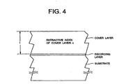
- This is a two-layer disc which is compatible in terms of reproduction or recording with a single-layer disc ( Fig. 4 ) on which reproduction or recording is performed by a predetermined reproducing or recording means through a cover layer on a recording layer on a light incident side surface having a predetermined refractive index n and a thickness t.
- the shallow recording layer other than the deepest recording layer, is covered with a cover layer having a thickness which is related to an optical distance d2 as expressed by d2 ⁇ n ⁇ t.
- the deepest recording layer is set at the optical distance d1 at the same position of the optical path thickness as the recording layer of the single-layer disc, information on the deepest recording layer at the optical distance d1 can be reproduced without searching for the position of the shallower recording layer of the multi-layer disc even by a pickup which is adapted to minimize the wave aberration for the single-layer disc.
- the optical distance d2 is set shorter than d1, an allowance for an inclined disc, when recording or reproducing is performed on the shallow recording layer, is not more strict than for the single-layer disc, so that the planarity need not be improved as compared with the single-layer disc.
- information may be recorded on the assumption that it is reproduced from the two layers in a predetermined order in which the shallow recording layer at the optical distance d2 is reproduced ahead of the deepest recording layer.
- physical address information can be recorded sequentially from the shallow recording layer to the deepest recording layer, in an order of shallower layers from the light incident side surface.
- signals are reproduced from the inner periphery to the outer periphery of the surface at the optical distance d2.
- signals may be reproduced from the outer periphery to the inner periphery of the surface at the optical distance d1.
- the physical address information can be recorded in order from the inner periphery to the outer periphery of the deepest recording layer.
- the two-layer disc for reproducing a program which exceeds a recording limit amount of the shallow recording layer, remaining information recorded on the deepest recording layer is reproduced after completion of reproduction from the shallow recording layer having a larger allowance for an inclined disc, so that it is possible to increase the allowance for a normally inclined disc.
- predetermined content information related to all contents on the two layers can be recorded on the deepest recording layer at the optical distance d1.
- a signal reproducing apparatus reads the title of the two-layer disc, a program recording time, or predetermined information indicating that this two-layer disc conforms to the opposite track path scheme or the like from the deepest recording layer at the optical distance d1, and then jumps a focused position to the inner periphery of the shallow recording layer at the optical distance d2 and can continue to reproduce signals.
- Physical address information may be sequentially recorded alternately in a forward direction from the inner periphery to the outer periphery and in the opposite direction from the outer periphery to the inner periphery in each recording layer in the order of depth from the deepest recording layer to the shallow recording layer.
- predetermined information indicative of the content of the disc over two layers can be read in the same wave aberration correcting state as a single-layer disc, so that the reproducing apparatus can be aware of a two-layer disc on which information is recorded without searching for the position of the recording layers by its wave aberration correcting unit, and can immediately start the reproduction.
- the optical pickup when the adjacent recording layers are reproduced from the shallow recording layer, the optical pickup can be smoothly moved between reproducing planes of the recording layers.
- This information may be such one that is recorded in an inner peripheral portion of the deepest recording layer as a pit, or a bar code, or what is called a PEF which forms a bar code like one using pits, or a wave aberration correcting signal for a region in which a signal is recorded for use in detection of wave aberration in order to correct the wave aberration.
- the objective lens When the numerical aperture of an objective lens for converging a light spot is chosen to be 0.8 or more, the objective lens is designed to minimize the amount of wave aberration when it focuses through the optical distance d1.
- the two-layer disc a disc having three or more layers can be designed in a similar manner, and other recording layers may also be provided even if they do not satisfy the foregoing condition. Also, while the recording density has not been described, the two recording layers may have the same recording density, or may differ from each other in recording density.
- the thickness of the cover layers has been described to be equal in the length of optical path. This can be of course realized by materials equal in the refractive index to each other and identical in thickness. Otherwise, even with materials having different refractive indexes, they may be sized to be equal in the product of the refractive index and thickness, i.e., the optical thickness (distance). Also, when a material (spacer) filled between layers has a different refractive index, it can be set to have an equivalent optical path length by sequential calculations.
- Each of the recording layers L1, L2 has a laminate structure comprised of a recording layer made of a phase changing material such as Ag-In-Sb-Te, and glass protection layers made of, for example, ZnS-SiO 2 or the like which sandwich the recording layer.
- a recording layer made of a phase changing material such as Ag-In-Sb-Te
- glass protection layers made of, for example, ZnS-SiO 2 or the like which sandwich the recording layer.
- each recording layer can be provided with a rewritable region in which data can be rewritten, i.e., recorded or erased, and a prepit region which is provided with trains of emboss pits that carry addresses as sequential physical addresses and information such as recording timing.
- the material for the recording layer is not limited to the phase changing material in the present invention, but a write-once pigment material may be used.
- the two-layer disc may be implemented as a disc dedicated to reproduction.
- the single-layer and multi-layer discs compatible for reproducing and recording are common in the disc diameter, overall disc thickness, track pitch, minimum pitch length, bowing angle, birefringence, format, and the like, other than the aforementioned conditions.
- these may conform to a CAV (constant angular velocity) or a CLV (constant linear velocity) scheme.
- they may be multi-layer disc in accordance with a zone CAV or a CLV scheme which is a combination of CAV and CLV.
- each recording layer of the multi-layer disc is previously formed with convex groove tracks and concave groove tracks alternately in a spiral or concentric shape. Each of the groove tracks may be wobbled at a frequency corresponding to the rotational speed of the multi-layer disc.
- Data is recorded on the multi-layer disc by irradiating a prepit region and a rewritable region of a recording layer thereof with a reproducing light beam having a low intensity (reading power) for scanning to detect land prepits and groove prepits in the prepit region, recognizing the position on a track to be recorded, and irradiating the rewritable region of the track with a focused recording light beam (writing power) having a high intensity modulated in accordance with the data.
- a reproducing light beam having a low intensity (reading power) for scanning to detect land prepits and groove prepits in the prepit region, recognizing the position on a track to be recorded, and irradiating the rewritable region of the track with a focused recording light beam (writing power) having a high intensity modulated in accordance with the data.
- Fig. 5 is a block diagram illustrating the configuration of a recording and reproducing apparatus according to the present example.
- An optical pickup 21 comprises an optical system which includes a focusing lens, a beam splitter, an objective lens, and the like; a semiconductor laser which is a light source; a photodetector; an objective lens actuator; and the like.
- the objective lens 21a has a numerical aperture equal to or larger than 0.8 and produces a focused spot of a light beam on a recording layer.
- the objective lens 21a is comprised of a group of lenses which minimize the amount of wave aberration of the light beam when either of a compatible single-layer or multi-layer disc is loaded at a normal position, and when the spot is focused at the optical distance d1 from the surface.
- the optical pickup 21 comprises a wave aberration correcting means 21b for varying the amount of wave aberration included in the focused spot.
- the optical pickup 21 When loading a multi-layer disc 1 onto a turntable 1a driven by a spindle motor, the optical pickup 21 irradiates the multi-layer disc 1 with a light beam as recording light or a reading light.
- the optical pickup 21 comprises the photodetector which detects a reflected light beam from a recording layer of the multi-layer disc to read a signal corresponding to a track and prepits or recording marks formed on the multi-layer disc 1 as a change in reflectivity.
- a servo circuit 20 has a focus servo circuit and a tracking servo circuit for performing a servo control for focusing and tracking of the pickup, a control for a reproduced position (radial position), a control for the rotational speed of the spindle motor, and the like based on a control signal provided from the optical pickup 21 and a control command provided from a control unit (CPU) 26.
- a focus servo circuit and a tracking servo circuit for performing a servo control for focusing and tracking of the pickup, a control for a reproduced position (radial position), a control for the rotational speed of the spindle motor, and the like based on a control signal provided from the optical pickup 21 and a control command provided from a control unit (CPU) 26.
- the optical beam is first irradiated to the deepest recording layer L2 at the optical distance d1, executes an initial focus servo operation, and performs a tracking servo and a focus servo control for the objective lens such that the light beam is focused correctly on the recording layer of the multi-layer disc.
- the focus servo circuit also executes a focus servo operation for jumping a focused position to the shallow recording layer L1 at the optical distance d2 after executing the initial focus servo operation.
- a read signal (RF signal) output from the optical pickup 21 is amplified in an amplifier circuit, and supplied to a pre-address decoder 23 and a decoder 43.
- the pre-address decoder 23 extracts prepits, wobble signals, and the like, and a synchronous clock and timing signal generator circuit within the pre-address decoder 23 generates a clock signal and a timing signal in synchronism with the rotation of the multi-layer disc 1.
- the timing signal represents a current position on the disc such as a prepit region or a writable region recorded (reproduced) by the light beam, or a land track or a groove track or the like.
- the pre-address decoder 23 reads address information from a signal read from emboss pits in the prepit region of the disc by the pickup, and sends the address information and timing signal to the CPU 26.
- the pre-address decoder 23 includes a circuit for detecting the rewritable region and prepit region on the multi-layer disc.
- the CPU 26 detects the position of the prepit region on the recording layer from these signals.
- a storage device is contained in or connected to the CPU 26 for storing necessary data and the like.
- the CPU 26 generally controls the apparatus based on signals supplied thereto.
- the CPU 26 reads the address information from the pre-address decoder 23, and sends a control command to a recording control circuit 36 and servo circuit 20 to control a recording and reproducing operation at a predetermined address.
- the recording control circuit 36 controls the power of the laser in the pickup in accordance with a particular state such as recording, erasing, reproducing and the like based on a control command from the CPU 26 and a timing signal from the pre-address decoder 23.
- a recording state the recording control circuit 36 modulates the power of the laser in the pickup based on a signal from an encoder 27 to record information on the disc.
- a reproducing state when data in the rewritable region is reproduced, or when address information in the prepit region is reproduced
- the recording control circuit 36 controls the reading power to maintain at constant low power so as not to erase information recorded on the disc.
- the encoder 27 adds a parity code for error correction to data to be recorded, and converts the resulting data to an RLL (Run Length Limited) code for encoding to a signal suitable for recording on the multi-layer disc 1.
- the encoded signal is sent from the encoder 27 to the recording control circuit 36.
- the decoder 43 performs the processing reverse to that performed in the encoder (demodulation of an RLL code, error correction, and the like) on a signal read from the rewritable region of the disc to recover originally recorded data.
- the present invention provides a multi-layer-information-recording medium which has two or more recording layer compatible with a single-layer disc, and a cover layer having the same optical path length as a cover layer of the single-layer disc, with another recording layer disposed at the position of a cover layer thinner than that, so that the multi-layer-information-recording medium excels in stability for planarity of the disc, and information can be recorded and reproduced in such an order that signals can be continuously reproduced from these recording layers.
Abstract
Description
- The present invention generally relates to an information recording medium such as an optical disc, an optical card and the like, and more particularly to a multi-layer-information-recording medium which has a plurality of recording layers layered on spacer layers.
- In recent years, optical discs are widely used as means for recording and reproducing data such as video data, audio data, computer data and the like. A high density recording disc called DVD (Digital Versatile Disc) has been used in practice. As one type of DVD, there is a multi-layer disc in a laminate structure which has a plurality of recording layers that can be read from one side of the disc. A two-layer disc having two recording layers on one side has been used in practice as a disc dedicated to reproduction.
- As illustrated in
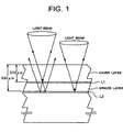
Fig. 1 , the two-layer DVD dedicated to reproduction comprises a shallow recording layer, which is the first layer viewed from the side on which data is read, i.e., closer to a light incident side surface, and a deep or second recording layer. With the two-layer disc, any signal recorded in the shallow recording layer and the deep recording layer can be read from one side of the disc only by moving the focus of a reproducing light beam. The shallow recording layer is made of a translucent film such that a light beam can transmit the shallow recording layer and read a signal from the deep recording layer, and the film thickness and material are chosen conveniently for the shallow recording layer. A reflective film is used for the deep recording layer. An optically transparent spacer layer having a high transmittance at the wavelength of light is disposed between the shallow recording layer and the deep recording layer in order to separate these layers by a constant distance. - The DVD standard defines that a transparent cover layer on a recording layer of a single-layer disc, having only one recording layer, 600 µm thick, as illustrated in
Fig. 2 . On the other hand, a two-layer disc is formed to have a first recording layer and a second recording layer positioned at depths of 570 µm and 630 µm from the surface on which a light beam is incident, i.e., above and below the depth of 600 µm at which the recording layer of a single-layer DVD is disposed. The positioning of the two layers above and below the single recording layer in the thickness direction is employed in the two-layer disc because an optical pickup system for recording and reproducing signals conforming to the DVD standard comprises an objective lens having a relatively small numerical aperture of 0.6 which is designed for the cover layer of 600 µm thick, and even with such an objective lens having a small numerical aperture, a deviation of approximately 30 µm in depth of the first layer and the second layer each from the single recording layer does not significantly affect the reading of signals. In this event, though the deviation of 30 µm of the recording layers causes wave aberration in a reading light beam, the amount of wave aberration is too small to cause a problem when the numerical aperture is on the order of 0.6. - A long program such as a movie which overflows the first recording layer of the two-layer disc is reproduced from the two recording layers. The DVD standard also defines a single side signal-reproducing scheme, called an opposite track path scheme, for continuously reproducing from two layers. The opposite track path scheme involves reproducing from the recording layer at a depth of 570 µm from the inner periphery to the outer periphery, jumping the focus from the outer periphery of this recording layer to the recording layer at a depth of 630 µm, and reproducing signals on the deeper recording layer from the outer periphery to the inner periphery. In this event, by reading an information region representing the contents of the disc recorded on the layer at a depth of 570 µm, the apparatus can sense the title of the DVD, a program duration, or the two-layer disc in accordance with the opposite track path scheme.
- Meanwhile, an increasing amount of information requires a higher density for next-generation optical disc. It is considered that the numerical aperture of the objective lens be increased to 0.8 or more for a higher density. When using an objective lens having such a large numerical aperture, the amount of wave aberration caused by an error in thickness of the cover layer on the recording layer increases too much to read signals, thereby failing to readily reproduce a next-generation optical disc when it is in a two recording layer structure. It is therefore considered that an optical system capable of adjusting the amount of wave aberration should be incorporated in a pickup to make a compensation for preventing the wave aberration in accordance with the depth of a recording layer.
- When an optical system for compensating for the wave aberration is used to read a single-layer disc and a multi-layer disc such as a two-layer disc of the next-generation while maintaining the compatibility, the difference exists in thickness of a cover layer corresponding to depths between the respective recording layers, so that a light beam must be focused on each recording layer while correcting the same for the wave aberration to search for lead-in information and the like. This gives rise to a problem that the time taken for starting reproduction becomes long if a two-layer disc is reproduced immediately after a single-layer disc was reproduced. In addition, with a large numerical aperture, a larger thickness of the cover layer causes an allowable range to be significantly narrowed down for the inclined disc, so that a multi-layer disc which has a larger thickness of cover layer than a single-layer disc must be fabricated with an improved planarity for the surface of the disc more than the single-layer disc.
- Document
US 6,175,548 discloses an optical recording medium which in several different embodiments can be a single layer optical disk as well as a dual layer optical disk. The thickness of the cover layer of the single layer medium and a sum of thicknesses of the cover and intermediate layers in the dual layer medium are in the same range: 3 182 µm There is, however, no information in this document about any compatibility kept between these two type of media regarding the positions of the recording layers. - The present invention has been made in view of the situation as described above, and it is an object of the invention to provide
- a multi-layer-information-recording medium which permits rapid data reproduction even when information is recorded or reproduced using an objective lens having a large numerical aperture of 0.8 or more, and which can be fabricated with an equivalent planarity to a single-layer disc, and an information recording and reproducing apparatus suitable for use with the multi-layer-information-recording medium.
- According to the present invention, there is provided a multi-layer-information-recording medium having a plurality of recording layers layered on a spacer layer on one side and applied to an information recording and reproducing apparatus capable of recording or reproducing information on a single-layer-information-recording medium having a single recording layer and a cover layer on one side as a change in reflectivity by irradiating a light beam through the cover layer onto the recording layer.
- The multi-layer-information-recording medium of the present invention comprises:
- a deepest recording layer disposed deepest from a light incident side surface at an optical distance d1 satisfying an equation d1 = nt wherein "n" denotes a predetermined refractive index of the cover layer of the single-layer-information-recording medium compatible in terms of at least reproducing and recording with said multi-layer-information-recording medium and "t" denotes a thickness of said cover layer; and
- at least one shallow recording layer disposed at an optical distance d2 satisfying an inequality d2 < nt from the light incident side surface.
- According to one aspect of the present invention, said multi-layer-information-recording medium comprises only two layers consisting of said deepest recording layer and said shallow recording layer.
- According to another aspect of the present invention of the multi-layer-information-recording medium, physical address information is recorded sequentially from said shallow recording layer to said deepest recording layer in a shallower order from the light incident side surface.
- According to a further aspect of the present invention of the multi-layer-information-recording medium, physical address information is sequentially recorded in order from an inner periphery to an outer periphery of said deepest recording layer.
- According to a still further aspect of the present invention of the multi-layer-information-recording medium, the physical address information is sequentially recorded alternately in a forward direction from the inner periphery to the outer periphery and in an opposite direction from the outer periphery to the inner periphery in each of the recording layers from said shallow recording layer to said deepest recording layer in the shallower order from the light incident side surface.
- According to an example of the present invention of the multi-layer-information-recording medium, predetermined content information related to all contents on said shallow recording layer is recorded in said deepest recording layer.
- According to an example of the present invention, there is also provided an information recording and reproducing apparatus capable of recording or reproducing information on either of a single-layer-information-recording medium having a single recording layer and a multi-layer-information-recording medium having a plurality of recording layers layered on a spacer layer on one side by irradiating a light beam thereto.
- The information recording and reproducing apparatus according to an example of the present invention comprises:
- an optical pickup having an objective lens which irradiates a light beam to a multi-layer-information-recording medium which includes a deepest recording layer disposed deepest from a light incident side surface at an optical distance d1 satisfying an equation d1 = nt wherein "n" denotes a predetermined refractive index of the cover layer of the single-layer-information-recording medium compatible in terms of at least reproducing and recording with said multi-layer-information-recording medium and "t" denotes a thickness of said cover layer, and at least one shallow recording layer disposed at an optical distance d2 satisfying an inequality d2 < nt from the light incident side surface; and
- a focus servo circuit which controls the objective lens to, first of all, focus the light beam to said deepest recording layer at the optical distance d1, and executes an initial focus servo operation.
- According to one aspect of the example of the information recording and reproducing apparatus, said focus servo circuit executes a focus servo operation for jumping a focused position to said shallow recording layer at the optical distance d2 after executing said initial focus servo operation.
- According to another aspect of the present example of the information recording and reproducing apparatus, said objective lens has a numerical aperture equal to or larger than 0.8 for producing a focused spot of the light beam
- According to a further aspect of the present example of the information recording and reproducing apparatus, the apparatus further comprises an wave aberration correcting portion which varies the amount of wave aberration included in said focused spot.
- According to a still further aspect of the present example of the information recording and reproducing apparatus, said objective lens comprises a group of lenses which minimizes the amount of wave aberration in the light beam when the spot is focused at a position spaced by the optical distance d1.
-
-
Fig. 1 is a cross-sectional view schematically showing a two-layer disc; -
Fig. 2 is a cross-sectional view schematically showing a single-layer disc; -
Fig. 3 is a cross-sectional view schematically showing a two-layer disc according to the present invention; -
Fig. 4 is a cross-sectional view schematically showing a single-layer disc which is compatible with the two-layer disc of the present invention; and -
Fig. 5 is a block diagram for schematically describing the configuration of a recording and reproducing apparatus according to the present invention. - Next, embodiments of the present invention will be described with reference to the accompanying drawings.
- An exemplary multi-layer disc according to a first embodiment of the present invention is a two-layer disc having a two-layer structure comprised of recording layers L1, L2, for example, as shown in
Fig. 3 . This is a two-layer disc which is compatible in terms of reproduction or recording with a single-layer disc (Fig. 4 ) on which reproduction or recording is performed by a predetermined reproducing or recording means through a cover layer on a recording layer on a light incident side surface having a predetermined refractive index n and a thickness t. - The deepest recording layer, i.e., the recording layer positioned deepest from the light incident side surface of the recording layers of the two-layer disc is covered with a cover layer having a thickness which is related to an optical distance d1 as expressed by d1 = n × t.
- The shallow recording layer, other than the deepest recording layer, is covered with a cover layer having a thickness which is related to an optical distance d2 as expressed by d2 < n × t. The two-layer disc comprises the deepest recording layer formed at the optical distance d1 which satisfies the equation d1 = n × t, and the shallow recording layer formed at the optical distance d2 which satisfies the inequality d2 < n × t.
- In this two-layer disc, since the deepest recording layer is set at the optical distance d1 at the same position of the optical path thickness as the recording layer of the single-layer disc, information on the deepest recording layer at the optical distance d1 can be reproduced without searching for the position of the shallower recording layer of the multi-layer disc even by a pickup which is adapted to minimize the wave aberration for the single-layer disc. Also, since the optical distance d2 is set shorter than d1, an allowance for an inclined disc, when recording or reproducing is performed on the shallow recording layer, is not more strict than for the single-layer disc, so that the planarity need not be improved as compared with the single-layer disc.
- With the two-layer disc, information may be recorded on the assumption that it is reproduced from the two layers in a predetermined order in which the shallow recording layer at the optical distance d2 is reproduced ahead of the deepest recording layer. Specifically, physical address information can be recorded sequentially from the shallow recording layer to the deepest recording layer, in an order of shallower layers from the light incident side surface.
- Further, with the two-layer disc, signals are reproduced from the inner periphery to the outer periphery of the surface at the optical distance d2. Alternatively, signals may be reproduced from the outer periphery to the inner periphery of the surface at the optical distance d1. Also, the physical address information can be recorded in order from the inner periphery to the outer periphery of the deepest recording layer.
- By thus designing the two-layer disc, for reproducing a program which exceeds a recording limit amount of the shallow recording layer, remaining information recorded on the deepest recording layer is reproduced after completion of reproduction from the shallow recording layer having a larger allowance for an inclined disc, so that it is possible to increase the allowance for a normally inclined disc.
- In the two-layer disc, predetermined content information related to all contents on the two layers can be recorded on the deepest recording layer at the optical distance d1. In this event, a signal reproducing apparatus reads the title of the two-layer disc, a program recording time, or predetermined information indicating that this two-layer disc conforms to the opposite track path scheme or the like from the deepest recording layer at the optical distance d1, and then jumps a focused position to the inner periphery of the shallow recording layer at the optical distance d2 and can continue to reproduce signals. Physical address information may be sequentially recorded alternately in a forward direction from the inner periphery to the outer periphery and in the opposite direction from the outer periphery to the inner periphery in each recording layer in the order of depth from the deepest recording layer to the shallow recording layer.
- With the disc on which information is recorded in the foregoing manner, predetermined information indicative of the content of the disc over two layers can be read in the same wave aberration correcting state as a single-layer disc, so that the reproducing apparatus can be aware of a two-layer disc on which information is recorded without searching for the position of the recording layers by its wave aberration correcting unit, and can immediately start the reproduction. Thus, according to the present invention, when the adjacent recording layers are reproduced from the shallow recording layer, the optical pickup can be smoothly moved between reproducing planes of the recording layers.
- This information may be such one that is recorded in an inner peripheral portion of the deepest recording layer as a pit, or a bar code, or what is called a PEF which forms a bar code like one using pits, or a wave aberration correcting signal for a region in which a signal is recorded for use in detection of wave aberration in order to correct the wave aberration.
- When the numerical aperture of an objective lens for converging a light spot is chosen to be 0.8 or more, the objective lens is designed to minimize the amount of wave aberration when it focuses through the optical distance d1.
- While the foregoing example has been described for the two-layer disc, a disc having three or more layers can be designed in a similar manner, and other recording layers may also be provided even if they do not satisfy the foregoing condition. Also, while the recording density has not been described, the two recording layers may have the same recording density, or may differ from each other in recording density.
- While in the foregoing example, the thickness of the cover layers has been described to be equal in the length of optical path. This can be of course realized by materials equal in the refractive index to each other and identical in thickness. Otherwise, even with materials having different refractive indexes, they may be sized to be equal in the product of the refractive index and thickness, i.e., the optical thickness (distance). Also, when a material (spacer) filled between layers has a different refractive index, it can be set to have an equivalent optical path length by sequential calculations.
- For example, assuming that the cover layer on the light incident side surface of the two-layer disc has a refractive index nc and a thickness tc, the shallow recording layer L1 has a refractive index nL1 and a thickness tL1, and a spacer layer between the recording layers L1, L2 has a refractive index ns and a thickness ts, the disc is designed such that the optical distance d1 from the surface on the light incident side of the deepest recording layer L2 satisfies d1 = n × t = nc × tc + nL1 × tL1 + ns × ts, and the optical distance d2 from the surface on the light incident side of the shallow recording layer L1 satisfies d2 = nc × tc < n × t.
- Each of the recording layers L1, L2 has a laminate structure comprised of a recording layer made of a phase changing material such as Ag-In-Sb-Te, and glass protection layers made of, for example, ZnS-SiO2 or the like which sandwich the recording layer. For an optical disc which uses a recording layer made of a phase changing material and on which data can be recorded or erased, i.e., rewritten using an optical beam, each recording layer can be provided with a rewritable region in which data can be rewritten, i.e., recorded or erased, and a prepit region which is provided with trains of emboss pits that carry addresses as sequential physical addresses and information such as recording timing. While an example of rewritable two-layer disc using a phase changing material is described, the material for the recording layer is not limited to the phase changing material in the present invention, but a write-once pigment material may be used. Moreover, the two-layer disc may be implemented as a disc dedicated to reproduction.
- The single-layer and multi-layer discs compatible for reproducing and recording are common in the disc diameter, overall disc thickness, track pitch, minimum pitch length, bowing angle, birefringence, format, and the like, other than the aforementioned conditions. For example, these may conform to a CAV (constant angular velocity) or a CLV (constant linear velocity) scheme. Alternatively, they may be multi-layer disc in accordance with a zone CAV or a CLV scheme which is a combination of CAV and CLV. In addition, each recording layer of the multi-layer disc is previously formed with convex groove tracks and concave groove tracks alternately in a spiral or concentric shape. Each of the groove tracks may be wobbled at a frequency corresponding to the rotational speed of the multi-layer disc.
- Data is recorded on the multi-layer disc by irradiating a prepit region and a rewritable region of a recording layer thereof with a reproducing light beam having a low intensity (reading power) for scanning to detect land prepits and groove prepits in the prepit region, recognizing the position on a track to be recorded, and irradiating the rewritable region of the track with a focused recording light beam (writing power) having a high intensity modulated in accordance with the data.
-
Fig. 5 is a block diagram illustrating the configuration of a recording and reproducing apparatus according to the present example. - An
optical pickup 21 comprises an optical system which includes a focusing lens, a beam splitter, an objective lens, and the like; a semiconductor laser which is a light source; a photodetector; an objective lens actuator; and the like. Theobjective lens 21a has a numerical aperture equal to or larger than 0.8 and produces a focused spot of a light beam on a recording layer. Theobjective lens 21a is comprised of a group of lenses which minimize the amount of wave aberration of the light beam when either of a compatible single-layer or multi-layer disc is loaded at a normal position, and when the spot is focused at the optical distance d1 from the surface. Theoptical pickup 21 comprises a wave aberration correcting means 21b for varying the amount of wave aberration included in the focused spot. - When loading a multi-layer disc 1 onto a
turntable 1a driven by a spindle motor, theoptical pickup 21 irradiates the multi-layer disc 1 with a light beam as recording light or a reading light. Theoptical pickup 21 comprises the photodetector which detects a reflected light beam from a recording layer of the multi-layer disc to read a signal corresponding to a track and prepits or recording marks formed on the multi-layer disc 1 as a change in reflectivity. Aservo circuit 20 has a focus servo circuit and a tracking servo circuit for performing a servo control for focusing and tracking of the pickup, a control for a reproduced position (radial position), a control for the rotational speed of the spindle motor, and the like based on a control signal provided from theoptical pickup 21 and a control command provided from a control unit (CPU) 26. When the multi-layer disc in the aforementioned example, for example, a two-layer disc is loaded, the optical beam is first irradiated to the deepest recording layer L2 at the optical distance d1, executes an initial focus servo operation, and performs a tracking servo and a focus servo control for the objective lens such that the light beam is focused correctly on the recording layer of the multi-layer disc. The focus servo circuit also executes a focus servo operation for jumping a focused position to the shallow recording layer L1 at the optical distance d2 after executing the initial focus servo operation. - A read signal (RF signal) output from the
optical pickup 21 is amplified in an amplifier circuit, and supplied to apre-address decoder 23 and adecoder 43. - The
pre-address decoder 23 extracts prepits, wobble signals, and the like, and a synchronous clock and timing signal generator circuit within thepre-address decoder 23 generates a clock signal and a timing signal in synchronism with the rotation of the multi-layer disc 1. The timing signal represents a current position on the disc such as a prepit region or a writable region recorded (reproduced) by the light beam, or a land track or a groove track or the like. Thepre-address decoder 23 reads address information from a signal read from emboss pits in the prepit region of the disc by the pickup, and sends the address information and timing signal to theCPU 26. Thepre-address decoder 23 includes a circuit for detecting the rewritable region and prepit region on the multi-layer disc. - The
CPU 26 detects the position of the prepit region on the recording layer from these signals. A storage device is contained in or connected to theCPU 26 for storing necessary data and the like. TheCPU 26 generally controls the apparatus based on signals supplied thereto. TheCPU 26 reads the address information from thepre-address decoder 23, and sends a control command to arecording control circuit 36 andservo circuit 20 to control a recording and reproducing operation at a predetermined address. - The
recording control circuit 36 controls the power of the laser in the pickup in accordance with a particular state such as recording, erasing, reproducing and the like based on a control command from theCPU 26 and a timing signal from thepre-address decoder 23. In a recording state, therecording control circuit 36 modulates the power of the laser in the pickup based on a signal from anencoder 27 to record information on the disc. In a reproducing state (when data in the rewritable region is reproduced, or when address information in the prepit region is reproduced), therecording control circuit 36 controls the reading power to maintain at constant low power so as not to erase information recorded on the disc. - The
encoder 27 adds a parity code for error correction to data to be recorded, and converts the resulting data to an RLL (Run Length Limited) code for encoding to a signal suitable for recording on the multi-layer disc 1. The encoded signal is sent from theencoder 27 to therecording control circuit 36. - The
decoder 43 performs the processing reverse to that performed in the encoder (demodulation of an RLL code, error correction, and the like) on a signal read from the rewritable region of the disc to recover originally recorded data. - As described above, the present invention provides a multi-layer-information-recording medium which has two or more recording layer compatible with a single-layer disc, and a cover layer having the same optical path length as a cover layer of the single-layer disc, with another recording layer disposed at the position of a cover layer thinner than that, so that the multi-layer-information-recording medium excels in stability for planarity of the disc, and information can be recorded and reproduced in such an order that signals can be continuously reproduced from these recording layers.
- It is understood that the foregoing description and accompanying drawings set forth the preferred embodiments of the invention at the present time.
- Thus, it should be appreciated that the invention is not limited to the disclosed embodiments but may be practiced within the full scope of the appended claims.
Claims (5)
- A multi-layer-information-recording medium that is in terms of reproducing or recording in a same format compatible with a single-layer-information-recording medium
having a single recording layer and a cover layer having a refractive index "n" and a thickness "t" on the light incident side,
said multi-layer-information-recording medium comprising a first recording layer (L1) and a second recording layer (L2) that are layered in order from a light incident side surface of the multi-layer-information-recording medium,
characterised in that
the second recording layer is disposed at an optical distance "d1" from the light incident side surface satisfying an equation d1 = n x t; and the first recording layer is disposed at an optical distance "d2" from the light incident side surface satisfying an inequality d2 < n x t, wherein "n" is the refractive index and "t" is the thickness of said cover layer; and
in that physical address information is recorded consecutively starting at said second recording layer (L2) and then following said first recording layer (L1) in order. - A multi-layer-information-recording medium according to claim 1, wherein physical address information is recorded in order from an inner periphery to an outer periphery of said second recording layer (L1).
- A multi-layer-information-recording medium according to claim 2, wherein physical address information is recorded in order from an outer periphery to an inner periphery of said first recording layer (L1).
- A multi-layer-information-recording medium according to any one of claims 1, 2 and 3, wherein compatibility of the multi-layer-information-recording medium and the single-layer-information-recording medium is common in disc diameter, overall disc thickness, and track pitch.
- A multi-layer-information-recording medium according to claim 4, wherein compatibility of the multi-layer-information-recording medium and the single-layer-information-recording medium is common in minimum pitch length, bowing angle, birefringence, and format.
Applications Claiming Priority (3)
| Application Number | Priority Date | Filing Date | Title |
|---|---|---|---|
| JP2001156477A JP2002352469A (en) | 2001-05-25 | 2001-05-25 | Multilayer information recording medium and information recording/reproducing device |
| JP2001156477 | 2001-05-25 | ||
| EP02010300A EP1260972B1 (en) | 2001-05-25 | 2002-05-21 | Information recording and reproducing apparatus and method |
Related Parent Applications (2)
| Application Number | Title | Priority Date | Filing Date |
|---|---|---|---|
| EP02010300.8 Division | 2002-05-21 | ||
| EP02010300A Division EP1260972B1 (en) | 2001-05-25 | 2002-05-21 | Information recording and reproducing apparatus and method |
Publications (2)
| Publication Number | Publication Date |
|---|---|
| EP1526525A1 EP1526525A1 (en) | 2005-04-27 |
| EP1526525B1 true EP1526525B1 (en) | 2011-01-05 |
Family
ID=19000481
Family Applications (3)
| Application Number | Title | Priority Date | Filing Date |
|---|---|---|---|
| EP05001939A Expired - Lifetime EP1526524B1 (en) | 2001-05-25 | 2002-05-21 | Multi-layer information recording medium and information recording and reproducing apparatus |
| EP05001940A Expired - Lifetime EP1526525B1 (en) | 2001-05-25 | 2002-05-21 | Multi-layer information recording medium and information recording and reproducing apparatus |
| EP02010300A Expired - Lifetime EP1260972B1 (en) | 2001-05-25 | 2002-05-21 | Information recording and reproducing apparatus and method |
Family Applications Before (1)
| Application Number | Title | Priority Date | Filing Date |
|---|---|---|---|
| EP05001939A Expired - Lifetime EP1526524B1 (en) | 2001-05-25 | 2002-05-21 | Multi-layer information recording medium and information recording and reproducing apparatus |
Family Applications After (1)
| Application Number | Title | Priority Date | Filing Date |
|---|---|---|---|
| EP02010300A Expired - Lifetime EP1260972B1 (en) | 2001-05-25 | 2002-05-21 | Information recording and reproducing apparatus and method |
Country Status (10)
| Country | Link |
|---|---|
| US (4) | US6773781B2 (en) |
| EP (3) | EP1526524B1 (en) |
| JP (1) | JP2002352469A (en) |
| KR (4) | KR100687990B1 (en) |
| CN (4) | CN1291403C (en) |
| AT (2) | ATE403930T1 (en) |
| DE (3) | DE60238875D1 (en) |
| ES (1) | ES2311566T3 (en) |
| HK (3) | HK1074909A1 (en) |
| TW (1) | TWI223253B (en) |
Families Citing this family (24)
| Publication number | Priority date | Publication date | Assignee | Title |
|---|---|---|---|---|
| AU2003232662A1 (en) * | 2002-06-05 | 2003-12-22 | Lg Electronics Inc. | High-density dual-layer optical disc |
| JP2004079071A (en) * | 2002-08-16 | 2004-03-11 | Pioneer Electronic Corp | Optical recording medium and optical recording method |
| US7489620B2 (en) | 2002-08-21 | 2009-02-10 | Nec Corporation | Optical information recording and reproducing medium |
| JP2004127390A (en) * | 2002-09-30 | 2004-04-22 | Toshiba Corp | Multilayered optical disk and optical disk recording and reproducing apparatus |
| WO2004032129A1 (en) * | 2002-10-02 | 2004-04-15 | Koninklijke Philips Electronics N.V. | Optical record carrier for use with uv radiation beam |
| CA2472075C (en) * | 2003-06-25 | 2013-02-26 | Matsushita Electric Industrial Co., Ltd. | Optical disk, method for manufacturing the same, and method for recording and method for reproducing data using optical disk |
| JP3782426B2 (en) * | 2003-08-07 | 2006-06-07 | 株式会社リコー | Optical information recording medium and recording / reproducing apparatus thereof |
| JP2005149606A (en) | 2003-11-14 | 2005-06-09 | Funai Electric Co Ltd | Optical pickup |
| US8264926B2 (en) * | 2003-12-26 | 2012-09-11 | Panasonic Corporation | Information recording medium with power calibration area |
| KR20070012639A (en) * | 2004-01-20 | 2007-01-26 | 코닌클리케 필립스 일렉트로닉스 엔.브이. | Focus control scheme with jumping focal point |
| JP2005244502A (en) * | 2004-02-25 | 2005-09-08 | Pioneer Electronic Corp | Optical disk recording apparatus, optical disk reproducing apparatus, and multilayer type optical disk |
| JP4713839B2 (en) * | 2004-03-17 | 2011-06-29 | 株式会社日立エルジーデータストレージ | Optical disc apparatus and focus jump control method thereof |
| JP4515292B2 (en) | 2004-05-25 | 2010-07-28 | 株式会社リコー | Information recording apparatus and information reproducing apparatus |
| KR100769626B1 (en) | 2004-09-17 | 2007-10-23 | 파이오니아 가부시키가이샤 | Information recording medium, information recording device and method, and information reproducing device and method |
| KR100871334B1 (en) | 2004-09-17 | 2008-12-01 | 파이오니아 가부시키가이샤 | Information recording medium, information recording device and method |
| WO2006041090A1 (en) | 2004-10-12 | 2006-04-20 | Pioneer Corporation | Information recording medium, apparatus and method for recording information, and computer program |
| JP2007128617A (en) * | 2005-11-04 | 2007-05-24 | Tdk Corp | Method for recording information to rewritable optical recording medium, rewritable optical recording medium, and information recording device to rewritable optical recording medium |
| CN101853672B (en) | 2007-10-19 | 2015-02-25 | 夏普株式会社 | Optical information storage medium reproduction apparatus and control method of the same |
| US8198083B1 (en) | 2007-10-31 | 2012-06-12 | William Gunter Loudon | Organotypic slices of the central nervous system |
| JP5408556B2 (en) * | 2008-03-27 | 2014-02-05 | 日本電気株式会社 | Optical disk drive device |
| US8130623B2 (en) * | 2008-05-23 | 2012-03-06 | Panasonic Corporation | Optical information recording and/or reproducing apparatus, optical information recording and/or reproducing method, optical information recording medium, and solid immersion lens |
| US8189452B2 (en) | 2009-08-24 | 2012-05-29 | Panasonic Corporation | Manufacturing method for optical recording medium, optical recording medium, optical information device, and information reproducing method |
| US8130628B2 (en) | 2009-08-25 | 2012-03-06 | Panasonic Corporation | Manufacturing method for optical recording medium, optical recording medium, optical information device, and information reproducing method |
| CN108112072A (en) * | 2016-11-24 | 2018-06-01 | 光宝电子(广州)有限公司 | Alignment system and its localization method |
Family Cites Families (21)
| Publication number | Priority date | Publication date | Assignee | Title |
|---|---|---|---|---|
| JPH0354740A (en) | 1989-07-24 | 1991-03-08 | Matsushita Electric Ind Co Ltd | Optical information recording member and optical information recording and reproducing device |
| US5303225A (en) * | 1989-10-30 | 1994-04-12 | Matsushita Electrical Industrial Co., Ltd. | Multi-layered optical disk with track and layer identification |
| US5202875A (en) | 1991-06-04 | 1993-04-13 | International Business Machines Corporation | Multiple data surface optical data storage system |
| US5838646A (en) * | 1991-09-11 | 1998-11-17 | Sony Corporation | Optical disk having a protective layer of specified thickness relative to the numerical aperture of the objective lens |
| JP3558306B2 (en) * | 1994-07-26 | 2004-08-25 | パイオニア株式会社 | Multilayer recording disk and recording / reproducing system using the same |
| JP3351164B2 (en) * | 1995-03-24 | 2002-11-25 | 日本ビクター株式会社 | Method for manufacturing optical information recording medium |
| KR100199298B1 (en) | 1995-06-08 | 1999-06-15 | 모리시따요오이 찌 | Dual-layered optical disc and pickup head |
| JP3751073B2 (en) * | 1995-06-08 | 2006-03-01 | 松下電器産業株式会社 | Optical disc playback system |
| JPH09138970A (en) | 1995-11-09 | 1997-05-27 | Pioneer Electron Corp | Double layer optical disk |
| KR19990011140A (en) * | 1997-07-21 | 1999-02-18 | 윤종용 | Optical disc |
| JPH11296904A (en) * | 1998-04-03 | 1999-10-29 | Toshiba Corp | Information recording medium and manufacture of resin substrate used for the same |
| US6175548B1 (en) * | 1998-06-29 | 2001-01-16 | Sony Corporation | Optical recording medium and optical recording and reproducing apparatus |
| JP2000235732A (en) * | 1999-02-12 | 2000-08-29 | Sony Corp | Multilayered optical disk |
| JP2001023244A (en) * | 1999-07-09 | 2001-01-26 | Sony Corp | Optical recording medium, its production and optical recording device |
| KR20010010565A (en) * | 1999-07-21 | 2001-02-15 | 윤종용 | Optical recording medium |
| JP2002050053A (en) * | 2000-08-01 | 2002-02-15 | Tdk Corp | Optical information medium |
| JP4150155B2 (en) * | 2000-10-10 | 2008-09-17 | 株式会社日立製作所 | Information recording medium, information recording method, reproducing method, recording / recording apparatus, and information reproducing apparatus |
| JP2002170276A (en) * | 2000-12-01 | 2002-06-14 | Pioneer Electronic Corp | Optical multi-layer information recording medium |
| TW588346B (en) * | 2000-12-22 | 2004-05-21 | Koninkl Philips Electronics Nv | Multilayer record carrier and method of manufacturing thereof and recording thereon |
| TW583660B (en) * | 2001-01-25 | 2004-04-11 | Koninkl Philips Electronics Nv | Optical information medium and a method of manufacturing the medium |
| JP3726254B2 (en) * | 2001-09-17 | 2005-12-14 | 日本ビクター株式会社 | Information recording medium manufacturing method |
-
2001
- 2001-05-25 JP JP2001156477A patent/JP2002352469A/en active Pending
-
2002
- 2002-05-20 US US10/147,979 patent/US6773781B2/en not_active Ceased
- 2002-05-21 EP EP05001939A patent/EP1526524B1/en not_active Expired - Lifetime
- 2002-05-21 AT AT02010300T patent/ATE403930T1/en not_active IP Right Cessation
- 2002-05-21 EP EP05001940A patent/EP1526525B1/en not_active Expired - Lifetime
- 2002-05-21 DE DE60238875T patent/DE60238875D1/en not_active Expired - Lifetime
- 2002-05-21 ES ES02010300T patent/ES2311566T3/en not_active Expired - Lifetime
- 2002-05-21 DE DE60239014T patent/DE60239014D1/en not_active Expired - Lifetime
- 2002-05-21 EP EP02010300A patent/EP1260972B1/en not_active Expired - Lifetime
- 2002-05-21 AT AT05001939T patent/ATE496371T1/en not_active IP Right Cessation
- 2002-05-21 DE DE60228019T patent/DE60228019D1/en not_active Expired - Lifetime
- 2002-05-22 TW TW091110806A patent/TWI223253B/en not_active IP Right Cessation
- 2002-05-24 CN CNB2004101006088A patent/CN1291403C/en not_active Expired - Lifetime
- 2002-05-24 CN CNB021204713A patent/CN1266692C/en not_active Expired - Lifetime
- 2002-05-24 CN CNB2004101006092A patent/CN100373483C/en not_active Expired - Fee Related
- 2002-05-24 CN CNB2006100957047A patent/CN100568359C/en not_active Expired - Lifetime
- 2002-05-25 KR KR1020020029075A patent/KR100687990B1/en active IP Right Grant
-
2003
- 2003-04-30 HK HK05107194.4A patent/HK1074909A1/en not_active IP Right Cessation
- 2003-04-30 HK HK05107195.3A patent/HK1074910A1/en not_active IP Right Cessation
- 2003-04-30 HK HK03103117.9A patent/HK1050954A1/en not_active IP Right Cessation
-
2004
- 2004-12-21 KR KR1020040109354A patent/KR100702269B1/en not_active IP Right Cessation
- 2004-12-21 KR KR1020040109355A patent/KR100699620B1/en active IP Right Grant
- 2004-12-21 KR KR1020040109353A patent/KR100699619B1/en active IP Right Grant
-
2005
- 2005-03-31 US US11/094,756 patent/USRE39322E1/en not_active Expired - Lifetime
- 2005-08-10 US US11/200,545 patent/USRE40556E1/en not_active Expired - Lifetime
- 2005-08-10 US US11/200,543 patent/USRE39463E1/en not_active Expired - Lifetime
Also Published As
Similar Documents
| Publication | Publication Date | Title |
|---|---|---|
| USRE39322E1 (en) | Multi-layer information recording medium and information recording and reproducing apparatus | |
| EP1777702B1 (en) | Optical information recording medium, and method and apparatus for recording/reproduction | |
| EP1202255A2 (en) | Multi-layer information recording medium and recording apparatus for the same | |
| US7885162B2 (en) | Information recording device and method, and recording control computer program | |
| EP2092521B1 (en) | Optical storage medium and respective apparatus for recording and/or reading data | |
| EP1837872B9 (en) | Information recording medium, information recording device and method, and computer program for controlling recording | |
| JP2005116176A (en) | Multilayer information recording medium and information reproducing device | |
| JP4641189B2 (en) | Information playback device | |
| JP2009037705A (en) | Information recording medium, information recording and reproducing device, and information recording and reproducing method | |
| JP2005116177A (en) | Multilayer information recording medium and information reproducing device | |
| WO2005081241A1 (en) | Optical information recording medium and information recording/reproduction device | |
| JP2004265475A (en) | Optical disk drive and its focus control method |
Legal Events
| Date | Code | Title | Description |
|---|---|---|---|
| PUAI | Public reference made under article 153(3) epc to a published international application that has entered the european phase |
Free format text: ORIGINAL CODE: 0009012 |
|
| AC | Divisional application: reference to earlier application |
Ref document number: 1260972 Country of ref document: EP Kind code of ref document: P |
|
| AK | Designated contracting states |
Kind code of ref document: A1 Designated state(s): AT BE CH CY DE DK ES FI FR GB GR IE IT LI LU MC NL PT SE TR |
|
| AX | Request for extension of the european patent |
Extension state: AL LV MK |
|
| 17P | Request for examination filed |
Effective date: 20050714 |
|
| REG | Reference to a national code |
Ref country code: HK Ref legal event code: DE Ref document number: 1074909 Country of ref document: HK |
|
| AKX | Designation fees paid |
Designated state(s): DE FR GB |
|
| GRAP | Despatch of communication of intention to grant a patent |
Free format text: ORIGINAL CODE: EPIDOSNIGR1 |
|
| GRAS | Grant fee paid |
Free format text: ORIGINAL CODE: EPIDOSNIGR3 |
|
| GRAA | (expected) grant |
Free format text: ORIGINAL CODE: 0009210 |
|
| AC | Divisional application: reference to earlier application |
Ref document number: 1260972 Country of ref document: EP Kind code of ref document: P |
|
| AK | Designated contracting states |
Kind code of ref document: B1 Designated state(s): DE FR GB |
|
| REG | Reference to a national code |
Ref country code: GB Ref legal event code: FG4D |
|
| REF | Corresponds to: |
Ref document number: 60238875 Country of ref document: DE Date of ref document: 20110217 Kind code of ref document: P |
|
| REG | Reference to a national code |
Ref country code: DE Ref legal event code: R096 Ref document number: 60238875 Country of ref document: DE Effective date: 20110217 |
|
| REG | Reference to a national code |
Ref country code: HK Ref legal event code: GR Ref document number: 1074909 Country of ref document: HK |
|
| REG | Reference to a national code |
Ref country code: DE Ref legal event code: R084 Ref document number: 60238875 Country of ref document: DE |
|
| REG | Reference to a national code |
Ref country code: GB Ref legal event code: 746 Effective date: 20110401 |
|
| PLBE | No opposition filed within time limit |
Free format text: ORIGINAL CODE: 0009261 |
|
| STAA | Information on the status of an ep patent application or granted ep patent |
Free format text: STATUS: NO OPPOSITION FILED WITHIN TIME LIMIT |
|
| 26N | No opposition filed |
Effective date: 20111006 |
|
| REG | Reference to a national code |
Ref country code: DE Ref legal event code: R097 Ref document number: 60238875 Country of ref document: DE Effective date: 20111006 |
|
| REG | Reference to a national code |
Ref country code: FR Ref legal event code: PLFP Year of fee payment: 14 |
|
| REG | Reference to a national code |
Ref country code: FR Ref legal event code: PLFP Year of fee payment: 15 |
|
| REG | Reference to a national code |
Ref country code: DE Ref legal event code: R082 Ref document number: 60238875 Country of ref document: DE Representative=s name: KLINGSEISEN, RINGS & PARTNER PATENTANWAELTE, DE |
|
| REG | Reference to a national code |
Ref country code: FR Ref legal event code: PLFP Year of fee payment: 16 |
|
| REG | Reference to a national code |
Ref country code: FR Ref legal event code: PLFP Year of fee payment: 17 |
|
| PGFP | Annual fee paid to national office [announced via postgrant information from national office to epo] |
Ref country code: DE Payment date: 20210427 Year of fee payment: 20 Ref country code: FR Payment date: 20210412 Year of fee payment: 20 |
|
| PGFP | Annual fee paid to national office [announced via postgrant information from national office to epo] |
Ref country code: GB Payment date: 20210429 Year of fee payment: 20 |
|
| REG | Reference to a national code |
Ref country code: DE Ref legal event code: R071 Ref document number: 60238875 Country of ref document: DE |
|
| REG | Reference to a national code |
Ref country code: GB Ref legal event code: PE20 Expiry date: 20220520 |
|
| PG25 | Lapsed in a contracting state [announced via postgrant information from national office to epo] |
Ref country code: GB Free format text: LAPSE BECAUSE OF EXPIRATION OF PROTECTION Effective date: 20220520 |