EP1526352A1 - Method and device for launching free-flying projectiles - Google Patents
Method and device for launching free-flying projectiles Download PDFInfo
- Publication number
- EP1526352A1 EP1526352A1 EP03445116A EP03445116A EP1526352A1 EP 1526352 A1 EP1526352 A1 EP 1526352A1 EP 03445116 A EP03445116 A EP 03445116A EP 03445116 A EP03445116 A EP 03445116A EP 1526352 A1 EP1526352 A1 EP 1526352A1
- Authority
- EP
- European Patent Office
- Prior art keywords
- projectile
- flying
- countermass
- powder
- piston
- Prior art date
- Legal status (The legal status is an assumption and is not a legal conclusion. Google has not performed a legal analysis and makes no representation as to the accuracy of the status listed.)
- Granted
Links
- 238000000034 method Methods 0.000 title claims abstract description 10
- 239000000843 powder Substances 0.000 claims abstract description 27
- 239000007789 gas Substances 0.000 claims description 17
- 238000010304 firing Methods 0.000 claims description 14
- 238000002485 combustion reaction Methods 0.000 claims description 5
- 230000033001 locomotion Effects 0.000 claims description 3
- 230000001133 acceleration Effects 0.000 claims 2
- 238000006243 chemical reaction Methods 0.000 claims 1
- 230000000977 initiatory effect Effects 0.000 claims 1
- 239000000779 smoke Substances 0.000 description 3
- VEXZGXHMUGYJMC-UHFFFAOYSA-N Hydrochloric acid Chemical compound Cl VEXZGXHMUGYJMC-UHFFFAOYSA-N 0.000 description 2
- 229910000831 Steel Inorganic materials 0.000 description 2
- 239000010959 steel Substances 0.000 description 2
- 239000002341 toxic gas Substances 0.000 description 2
- 238000013459 approach Methods 0.000 description 1
- 230000006378 damage Effects 0.000 description 1
- 238000006073 displacement reaction Methods 0.000 description 1
- 239000000428 dust Substances 0.000 description 1
- 230000009760 functional impairment Effects 0.000 description 1
- 229910001385 heavy metal Inorganic materials 0.000 description 1
- 230000009545 invasion Effects 0.000 description 1
- 239000002245 particle Substances 0.000 description 1
- 230000001012 protector Effects 0.000 description 1
- 230000000717 retained effect Effects 0.000 description 1
- 239000000126 substance Substances 0.000 description 1
Images

Classifications
-
- F—MECHANICAL ENGINEERING; LIGHTING; HEATING; WEAPONS; BLASTING
- F41—WEAPONS
- F41F—APPARATUS FOR LAUNCHING PROJECTILES OR MISSILES FROM BARRELS, e.g. CANNONS; LAUNCHERS FOR ROCKETS OR TORPEDOES; HARPOON GUNS
- F41F3/00—Rocket or torpedo launchers
- F41F3/04—Rocket or torpedo launchers for rockets
- F41F3/045—Rocket or torpedo launchers for rockets adapted to be carried and used by a person, e.g. bazookas
- F41F3/0455—Bazookas
-
- F—MECHANICAL ENGINEERING; LIGHTING; HEATING; WEAPONS; BLASTING
- F41—WEAPONS
- F41A—FUNCTIONAL FEATURES OR DETAILS COMMON TO BOTH SMALLARMS AND ORDNANCE, e.g. CANNONS; MOUNTINGS FOR SMALLARMS OR ORDNANCE
- F41A1/00—Missile propulsion characterised by the use of explosive or combustible propellant charges
- F41A1/08—Recoilless guns, i.e. guns having propulsion means producing no recoil
- F41A1/10—Recoilless guns, i.e. guns having propulsion means producing no recoil a counter projectile being used to balance recoil
Definitions
- the present invention relates to a method and a device for launching free-flying projectiles and primarily those which form part of heavier carried support weapons such as antitank rifles, antitank grenade launchers and lighter antitank missiles.
- the particularly great advantage of the invention is that it makes it possible to develop effective weapons of the types mentioned above which are well-suited for firing from inside buildings or other largely closed spaces.
- the main advantages of the method and the device according to the invention are that the launching methodology introduced therein does not give rise to any pressure surges which are disturbing for the weapon operator or his comrades at the same time as it gives rise to only low sound pressure and, in its most refined variant, no dangerous gases whatsoever, and this notwithstanding the fact that the launching takes place by means of combustion of what is in principle an entirely conventional propellent powder charge.
- the most considerable advantage of the method according to the invention is furthermore that launching takes place without the propellent powder charge utilized in this connection giving rise to any open flame or smoke which would reveal the position of the weapon operator when firing takes place.
- the invention is based on a modified use of what is known as a countermass which is accelerated backwards by the propellent powder charge in relation to the desired flying direction of the projectile concerned at the same time as the projectile is accelerated to the desired speed in the intended flying direction.
- Antitank rifles, antitank grenade launchers and lighter antitank missiles but also some other slightly heavier weapons which function according to the countermass principle have been in service in the majority of armies for several years. With one or a few exceptions, however, these weapons which exist today have been completely impossible to fire from closed confined spaces without the crew handling the weapon having been exposed to great risks and in most cases very serious injuries.
- At least one weapon which functions in this way exists today, and there are probably several similar at the experimental stage. These weapons are probably based on utilization of two movable pistons built into the launching device or barrel of the weapon, which are driven away from one another when combustion of a propellent powder charge included in the weapon takes place, the front piston accelerating the projectile forwards out of the barrel in the desired firing direction while the rear one drives the countermass backwards out of the rear outlet of the barrel. When the pistons reach the respective ends of the barrel, they are braked and provide a seal against the powder gases. The barrel of the weapon has thus been transformed into a high-pressure container with a considerable internal pressure, from which the confined powder gases are allowed to escape slowly.
- the propellent powder charge and the countermass are moved from the launching device or the barrel and are instead built into the projectile, and that use is made of a single displaceable piston which, when combustion of the propellent powder charge takes place, is displaced inside the projectile and in the course of this drives the countermass out of the rear part of the projectile at the same time as the projectile is accelerated in the opposite direction.
- the projectile designed in accordance with the present invention will therefore contain the necessary payload, a propellent powder charge in a reinforced rear pressure chamber designed therefor, a piston which can be displaced backwards in relation to the intended flying direction of the projectile in the pressure chamber, and, behind this piston, a simple countermass which could consist of, for example, suitably packed steel shot.
- the barrel of the weapon can, in contrast to the more heavily constructed projectile, be made relatively light as it will never be subjected to any high internal pressure.
- the barrel must of course comprise the necessary firing and sight functions.
- the propellent powder charge is thus ignited, the pressure in front of the piston then increasing, which results in the latter, inside the pressure chamber, being driven backwards in relation to the intended flying direction of the projectile at the same time as it drives the countermass out of a rear opening in the projectile chamber, which means that the projectile is at the same time accelerated in the intended flying direction.
- the piston approaches the rear end of the chamber, it is braked by, for example, deformation against shoulders or stops arranged in the chamber wall.
- the projectile and the countermass are nevertheless not hindered in their movements but leave the barrel through the front and, respectively, rear outlets thereof without in doing so giving rise to any flame, smoke or other detectable signature.
- the projectile therefore continues with its built-in high-pressure chamber towards the intended target at the same time as the barrel of the weapon can immediately be reloaded and fired again. With the weapon, no risks remain for the weapon operator or anyone around him.
- the weapon shown in the figures comprises a barrel 1 with a shoulder rest 2 and a pistol grip, with firing means 3, intended for the weapon operator.
- the weapon also comprises a projectile 4 with an active load 5 and a rear pressure chamber 6 in which an axially displaceable piston 7 is arranged.
- a countermass 8 which can consist of, for example, steel shot packed in a suitable manner.
- the projectile 4 is also provided with fins 9 which are folded in in Figures 1 and 2.
- a charging compartment 10 is arranged in the front part of the piston 7 facing the active load. To begin with, this charging compartment contains a propellent powder charge 11 and an igniter 12.
- the propellent powder charge 11 is initiated by the igniter 12, and the powder gases then formed drive the piston 7 backwards in relation to the firing direction of the weapon inside the pressure chamber 6 at the same time as the countermass 8 starts to be forced out through the rear outlet 13 of the projectile and the projectile 4 is accelerated forwards in the firing direction a of the weapon and out of the muzzle 14 of the barrel 1.
- the piston 7 will have reached its rearmost position in the pressure chamber 6, and the piston will be blocked in this position by, for example, being compressed firmly so that the powder gases which to begin with drive the piston are retained inside the pressure chamber.'
- a projecting edge 15 has been drawn in the figures. As can be seen from Figure 3, the fins 9 are folded out when the projectile goes into free flight. The same figure shows the piston 7 in a firmly compressed sealed position.
Landscapes
- Engineering & Computer Science (AREA)
- General Engineering & Computer Science (AREA)
- Chemical & Material Sciences (AREA)
- Combustion & Propulsion (AREA)
- Aiming, Guidance, Guns With A Light Source, Armor, Camouflage, And Targets (AREA)
- Toys (AREA)
- Saccharide Compounds (AREA)
- Analysing Materials By The Use Of Radiation (AREA)
Abstract
Description
- The present invention relates to a method and a device for launching free-flying projectiles and primarily those which form part of heavier carried support weapons such as antitank rifles, antitank grenade launchers and lighter antitank missiles. The particularly great advantage of the invention is that it makes it possible to develop effective weapons of the types mentioned above which are well-suited for firing from inside buildings or other largely closed spaces.
- It is increasingly clear that combat in buildings is a very likely scenario in the future, irrespective of whether it is a matter of an international effort, defence against invasion or combating terrorism. Combat in buildings in turn requires it to be possible for firing with all carried weapons to be carried out inside buildings or out from buildings. To have to run outdoors as soon as it is intended to open fire involves losing time but above all leaving the protection the building after all offers. It has to be possible for firing indoors to be carried out without risk to weapon operators or other people in the same or adjoining room or space.
- However, modern heavy carried support weapons of the antitank rifle, antitank grenade launcher and lighter antitank missile type give rise to violent pressure surges which, owing to the fact that indoors they will be reflected over and over again against walls and corners and back towards the weapon operator, exceed many times over the level a person tolerates without functional impairment. They also give rise to toxic gases such as primarily CO and NOx but also hydrochloric acid, lead dust and other heavy metals, and they moreover leave clear signatures in the form of flames and smoke.
- The main advantages of the method and the device according to the invention are that the launching methodology introduced therein does not give rise to any pressure surges which are disturbing for the weapon operator or his comrades at the same time as it gives rise to only low sound pressure and, in its most refined variant, no dangerous gases whatsoever, and this notwithstanding the fact that the launching takes place by means of combustion of what is in principle an entirely conventional propellent powder charge. Perhaps the most considerable advantage of the method according to the invention is furthermore that launching takes place without the propellent powder charge utilized in this connection giving rise to any open flame or smoke which would reveal the position of the weapon operator when firing takes place. The invention is based on a modified use of what is known as a countermass which is accelerated backwards by the propellent powder charge in relation to the desired flying direction of the projectile concerned at the same time as the projectile is accelerated to the desired speed in the intended flying direction.
- Antitank rifles, antitank grenade launchers and lighter antitank missiles but also some other slightly heavier weapons which function according to the countermass principle have been in service in the majority of armies for several years. With one or a few exceptions, however, these weapons which exist today have been completely impossible to fire from closed confined spaces without the crew handling the weapon having been exposed to great risks and in most cases very serious injuries. By utilizing countermass instead of the refined blowback principle, it is true that it has been possible to reduce considerably the quantity of propellent powder necessary in order to give the projectile a certain desired launching speed, but risks still remain then in the form of signature, particles, irritating substances, toxic gases, high sound pressure and the pressure increase still present when the projectile and the countermass leave the muzzle of the barrel and, respectively, its rear outlet.
- If the weapon does not discharge the powder gases, no flame, pressure or signature originates from these either. It is then also easier to select possible countermasses which have less of a signature and irritating capacity.
- At least one weapon which functions in this way exists today, and there are probably several similar at the experimental stage. These weapons are probably based on utilization of two movable pistons built into the launching device or barrel of the weapon, which are driven away from one another when combustion of a propellent powder charge included in the weapon takes place, the front piston accelerating the projectile forwards out of the barrel in the desired firing direction while the rear one drives the countermass backwards out of the rear outlet of the barrel. When the pistons reach the respective ends of the barrel, they are braked and provide a seal against the powder gases. The barrel of the weapon has thus been transformed into a high-pressure container with a considerable internal pressure, from which the confined powder gases are allowed to escape slowly.
- One example of such a weapon is described in US-A-5,313,870.
- The disadvantage of this solution is that the barrel of the weapon has to be made very heavy in order to be capable of stopping the pistons and that it is a non-reloadable single-use weapon, the existence of which as a pressurized gas container after firing could involve a certain risk factor.
- In accordance with the present invention, it is now proposed instead that the propellent powder charge and the countermass are moved from the launching device or the barrel and are instead built into the projectile, and that use is made of a single displaceable piston which, when combustion of the propellent powder charge takes place, is displaced inside the projectile and in the course of this drives the countermass out of the rear part of the projectile at the same time as the projectile is accelerated in the opposite direction. This means that the projectile is somewhat heavier to begin with but that the barrel of the weapon, which therefore, in this development of the piston-driving principle, does not then have to be capable of taking up either the movements of the pistons or the internal powder gas pressure, can be made lighter and at the same time is reloadable immediately after firing.
- The projectile designed in accordance with the present invention will therefore contain the necessary payload, a propellent powder charge in a reinforced rear pressure chamber designed therefor, a piston which can be displaced backwards in relation to the intended flying direction of the projectile in the pressure chamber, and, behind this piston, a simple countermass which could consist of, for example, suitably packed steel shot. At the same time, the barrel of the weapon can, in contrast to the more heavily constructed projectile, be made relatively light as it will never be subjected to any high internal pressure. On the other hand, the barrel must of course comprise the necessary firing and sight functions.
- When the weapon according to the invention is fired, the propellent powder charge is thus ignited, the pressure in front of the piston then increasing, which results in the latter, inside the pressure chamber, being driven backwards in relation to the intended flying direction of the projectile at the same time as it drives the countermass out of a rear opening in the projectile chamber, which means that the projectile is at the same time accelerated in the intended flying direction. When the piston approaches the rear end of the chamber, it is braked by, for example, deformation against shoulders or stops arranged in the chamber wall. The projectile and the countermass are nevertheless not hindered in their movements but leave the barrel through the front and, respectively, rear outlets thereof without in doing so giving rise to any flame, smoke or other detectable signature. The projectile therefore continues with its built-in high-pressure chamber towards the intended target at the same time as the barrel of the weapon can immediately be reloaded and fired again. With the weapon, no risks remain for the weapon operator or anyone around him.
- Gastight, signatureless firing, low sound pressure which allows firing without ear protectors even in small spaces. Reloadable light launching device in a weapon which can be provided with high performance with launching speeds of over 200 m/s and allows relatively heavy active parts to be launched directly from the shoulder.
- The method and the device according to the invention have been defined in the patent claims below and will now be described in somewhat greater detail in connection with accompanying figures.
-
- Figures 1 and 2 show a sectioned projection of an antitank weapon according to the invention immediately before and during the initial launching phase of the projectile included therein.
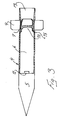
- Figure 3 shows the likewise sectioned projectile after it has left the barrel of the weapon and is on its way towards its target.
-
- All components have been given the same reference designations in the various figures.
- The weapon shown in the figures comprises a
barrel 1 with a shoulder rest 2 and a pistol grip, with firing means 3, intended for the weapon operator. The weapon also comprises aprojectile 4 with anactive load 5 and arear pressure chamber 6 in which an axiallydisplaceable piston 7 is arranged. To begin with, that is to say until the weapon is fired, the main part of this pressure chamber is filled by acountermass 8 which can consist of, for example, steel shot packed in a suitable manner. Theprojectile 4 is also provided with fins 9 which are folded in in Figures 1 and 2. Furthermore, acharging compartment 10 is arranged in the front part of thepiston 7 facing the active load. To begin with, this charging compartment contains a propellent powder charge 11 and an igniter 12. - When the weapon is fired, the propellent powder charge 11 is initiated by the igniter 12, and the powder gases then formed drive the
piston 7 backwards in relation to the firing direction of the weapon inside thepressure chamber 6 at the same time as thecountermass 8 starts to be forced out through therear outlet 13 of the projectile and theprojectile 4 is accelerated forwards in the firing direction a of the weapon and out of the muzzle 14 of thebarrel 1. At the moment when all the countermass has left thepressure chamber 6, thepiston 7 will have reached its rearmost position in thepressure chamber 6, and the piston will be blocked in this position by, for example, being compressed firmly so that the powder gases which to begin with drive the piston are retained inside the pressure chamber.' In order to illustrate this, a projectingedge 15 has been drawn in the figures. As can be seen from Figure 3, the fins 9 are folded out when the projectile goes into free flight. The same figure shows thepiston 7 in a firmly compressed sealed position. - The expression pressure chamber has been used above for the
space 6 to begin with as well, when this space is occupied by thecountermass 8, but this space does not actually become a pressure chamber until thecharging compartment 10 has been enlarged to comprise this space as well by the displacement of thepiston 7. In the patent claims and the abstract, the expression pressure chamber has therefore been given thereference designation
Claims (6)
- Method of, without gas discharge to the surrounding environment, accelerating the speed of a projectile (4) from zero to a speed which gives the projectile free-flying characteristics by converting at least some of the expansion force from a propellent powder charge (11) which discharges gas when it is initiated and is enclosed in a gastight container (6, 10) which can be expanded at least up to certain limits, characterized in that the powder gases formed when the propellent powder charge (11) is initiated are utilized for driving a countermass (8) out of the rear part (13) of the projectile in the direction opposite to the desired flying direction (a) and thus at the same time as a reaction giving the projectile the desired acceleration in the flying direction (a).
- Method according to Claim 1, characterized in that the gastight container (6, 10) in which the propellent powder charge (11) is initiated and in which powder gases formed in that connection are contained is separated from the countermass by a piston (7) which is displaceable in the intended direction of movement of the countermass, that is to say backwards in relation to the intended flying direction of the projectile, and can be caught at the rear end of the gastight container.
- Method according to Claim 2, characterized in that the piston (7) which is displaceable in the gastight container (6, 10) of the projectile (4) is compressed firmly in its intended end position.
- Powder-gas-driven free-flying projectile (4) which is accelerated to the desired flying speed by combustion of a propellent powder charge (11) inside a pressure chamber (6, 10) intended therefor, a piston (7), which is arranged in the pressure chamber, is displaced in a direction opposite to the desired flying direction (a) of the projectile when combustion of the powder gases takes place and simultaneously acts on a countermass (8), giving the projectile its desired acceleration in the flying direction (a), characterized in that the pressure chamber (6, 10) with the piston (7) displaceable therein and also the countermass (8) are to begin with arranged inside the rear part of the projectile (4).
- Powder-gas-driven free-flying projectile according to Claim 4, characterized in that the pressure chamber (6, 10) arranged inside the rear part of the projectile is designed (15) in such a way in its rearmost part that it allows the countermass (8) in its entirety to pass out but brakes and retains the piston (7) in a rear stop position which is sealed relative to the pressure chamber wall (6, 10) against the powder gases.
- Powder-gas-driven free-flying projectile according to Claims 4 and 5, characterized in that it is fired from a launching device (1) in the form of a barrel comprising means (3) for initiation of the powder charge (11) and also the necessary sights, the length of the barrel (1) forwards in the firing direction and backwards in relation to the same being adapted in such a way that the projectile (4) leaves the barrel muzzle (14) at the same time as the last part of the countermass (8) leaves the rear part of the barrel.
Priority Applications (7)
| Application Number | Priority Date | Filing Date | Title |
|---|---|---|---|
| DE60303789T DE60303789T2 (en) | 2003-10-20 | 2003-10-20 | Method and apparatus for firing exposed projectiles |
| EP03445116A EP1526352B1 (en) | 2003-10-20 | 2003-10-20 | Method and device for launching free-flying projectiles |
| AT03445116T ATE319065T1 (en) | 2003-10-20 | 2003-10-20 | DEVICE AND METHOD FOR FIRING A FREE-FLYING PROJECTILE |
| ES03445116T ES2257659T3 (en) | 2003-10-20 | 2003-10-20 | METHOD AND DEVICE FOR THE LAUNCH OF FREE FLIGHT PROJECTILES. |
| ZA200408454A ZA200408454B (en) | 2003-10-20 | 2004-10-19 | Method and device for launching free-flying projectiles. |
| JP2004303622A JP2005127704A (en) | 2003-10-20 | 2004-10-19 | Method and device for launching free-flying projectile |
| US10/968,267 US7305911B2 (en) | 2003-10-20 | 2004-10-20 | Method and device for launching free-flying projectiles |
Applications Claiming Priority (1)
| Application Number | Priority Date | Filing Date | Title |
|---|---|---|---|
| EP03445116A EP1526352B1 (en) | 2003-10-20 | 2003-10-20 | Method and device for launching free-flying projectiles |
Publications (2)
| Publication Number | Publication Date |
|---|---|
| EP1526352A1 true EP1526352A1 (en) | 2005-04-27 |
| EP1526352B1 EP1526352B1 (en) | 2006-03-01 |
Family
ID=34384750
Family Applications (1)
| Application Number | Title | Priority Date | Filing Date |
|---|---|---|---|
| EP03445116A Expired - Lifetime EP1526352B1 (en) | 2003-10-20 | 2003-10-20 | Method and device for launching free-flying projectiles |
Country Status (7)
| Country | Link |
|---|---|
| US (1) | US7305911B2 (en) |
| EP (1) | EP1526352B1 (en) |
| JP (1) | JP2005127704A (en) |
| AT (1) | ATE319065T1 (en) |
| DE (1) | DE60303789T2 (en) |
| ES (1) | ES2257659T3 (en) |
| ZA (1) | ZA200408454B (en) |
Cited By (4)
| Publication number | Priority date | Publication date | Assignee | Title |
|---|---|---|---|---|
| EP2161531A1 (en) | 2008-09-04 | 2010-03-10 | Saab AB | Countermass weapon |
| CN102809326A (en) * | 2012-08-14 | 2012-12-05 | 山东军兴机械有限公司 | Recoilless explosive disintegrating bomb with adjustable chamber pressure |
| ES2415778R1 (en) * | 2011-04-05 | 2013-09-19 | Gracia Faustino Cantos | COMPENSATED REVERSE FIREARM |
| CN113587725A (en) * | 2021-07-06 | 2021-11-02 | 中国矿业大学 | Pressure equalizing system for underwater missile launching shaft |
Families Citing this family (5)
| Publication number | Priority date | Publication date | Assignee | Title |
|---|---|---|---|---|
| WO2015083112A1 (en) * | 2013-12-05 | 2015-06-11 | Эрвинс БЛУМВЕРГ | Projectile gun piston |
| CN109668712B (en) * | 2018-12-29 | 2020-08-04 | 中国空气动力研究与发展中心超高速空气动力研究所 | Model launching device and application thereof |
| RU201079U1 (en) * | 2020-04-28 | 2020-11-26 | Илья Григорьевич Вишняков | Disposable grenade launcher |
| US11959711B1 (en) * | 2021-10-15 | 2024-04-16 | The United States Of America As Represented By The Secretary Of The Army | Recoilless gun and ammunition |
| CN115230980A (en) * | 2022-08-30 | 2022-10-25 | 山西鑫跃达机电设备制造有限公司 | A swarm unmanned aerial vehicle unsupported launcher |
Citations (4)
| Publication number | Priority date | Publication date | Assignee | Title |
|---|---|---|---|---|
| US4406209A (en) * | 1979-11-22 | 1983-09-27 | Societe D'etudes, De Realisations Et D'applications Techniques (S.E.R.A.T) | Projectile-firing weapons |
| WO1989004451A1 (en) * | 1987-11-10 | 1989-05-18 | The Secretary Of State For Defence In Her Britanni | Recoil-less launch system |
| US5313870A (en) * | 1990-09-27 | 1994-05-24 | The Secretary Of State For Defence In Her Britannic Majesty's Government Of The United Kingdom Of Great Britain And Northern Ireland | Double piston propulsion unit |
| GB2314913A (en) * | 1987-07-16 | 1998-01-14 | Hunting Eng Ltd | Projectile launching device |
Family Cites Families (8)
| Publication number | Priority date | Publication date | Assignee | Title |
|---|---|---|---|---|
| DE3048597A1 (en) * | 1980-12-23 | 1982-07-22 | Dynamit Nobel Ag, 5210 Troisdorf | ARRANGEMENT WITH SHOCK-FREE ARMS |
| CH668473A5 (en) * | 1985-11-29 | 1988-12-30 | Oerlikon Buehrle Ag | DEVICE FOR SHOCK-FREE SHOOTING OF BULLETS FROM A LAUNCH TUBE. |
| GB9105692D0 (en) * | 1991-03-18 | 1991-05-01 | Secr Defence | Projectile launcher |
| US5965836A (en) * | 1996-08-29 | 1999-10-12 | Rakov; Mikhail A. | Method and devices for propulsion |
| US5952601A (en) * | 1998-04-23 | 1999-09-14 | The United States Of America As Represented By The Secretary Of The Navy | Recoilless and gas-free projectile propulsion |
| US6543329B2 (en) * | 2000-11-08 | 2003-04-08 | The United States Of America As Represented By The Secretary Of The Navy | Nested ring based countermass assembly |
| US6446535B1 (en) * | 2001-02-16 | 2002-09-10 | The United States Of America As Represented By The Secretary Of The Navy | Triple-tube, dispersible countermass recoilless projectile launcher system |
| SE520975C2 (en) * | 2002-01-31 | 2003-09-16 | Saab Ab | Methods of producing counter-mass weapons, device at counter-mass weapons and counter-mass weapons |
-
2003
- 2003-10-20 DE DE60303789T patent/DE60303789T2/en not_active Expired - Lifetime
- 2003-10-20 EP EP03445116A patent/EP1526352B1/en not_active Expired - Lifetime
- 2003-10-20 ES ES03445116T patent/ES2257659T3/en not_active Expired - Lifetime
- 2003-10-20 AT AT03445116T patent/ATE319065T1/en not_active IP Right Cessation
-
2004
- 2004-10-19 JP JP2004303622A patent/JP2005127704A/en active Pending
- 2004-10-19 ZA ZA200408454A patent/ZA200408454B/en unknown
- 2004-10-20 US US10/968,267 patent/US7305911B2/en not_active Expired - Fee Related
Patent Citations (4)
| Publication number | Priority date | Publication date | Assignee | Title |
|---|---|---|---|---|
| US4406209A (en) * | 1979-11-22 | 1983-09-27 | Societe D'etudes, De Realisations Et D'applications Techniques (S.E.R.A.T) | Projectile-firing weapons |
| GB2314913A (en) * | 1987-07-16 | 1998-01-14 | Hunting Eng Ltd | Projectile launching device |
| WO1989004451A1 (en) * | 1987-11-10 | 1989-05-18 | The Secretary Of State For Defence In Her Britanni | Recoil-less launch system |
| US5313870A (en) * | 1990-09-27 | 1994-05-24 | The Secretary Of State For Defence In Her Britannic Majesty's Government Of The United Kingdom Of Great Britain And Northern Ireland | Double piston propulsion unit |
Cited By (6)
| Publication number | Priority date | Publication date | Assignee | Title |
|---|---|---|---|---|
| EP2161531A1 (en) | 2008-09-04 | 2010-03-10 | Saab AB | Countermass weapon |
| US8220376B2 (en) | 2008-09-04 | 2012-07-17 | Saab Ab | Countermass weapon |
| ES2415778R1 (en) * | 2011-04-05 | 2013-09-19 | Gracia Faustino Cantos | COMPENSATED REVERSE FIREARM |
| CN102809326A (en) * | 2012-08-14 | 2012-12-05 | 山东军兴机械有限公司 | Recoilless explosive disintegrating bomb with adjustable chamber pressure |
| CN102809326B (en) * | 2012-08-14 | 2015-04-15 | 张建中 | Recoilless explosive disintegrating bomb with adjustable chamber pressure |
| CN113587725A (en) * | 2021-07-06 | 2021-11-02 | 中国矿业大学 | Pressure equalizing system for underwater missile launching shaft |
Also Published As
| Publication number | Publication date |
|---|---|
| US20070256552A1 (en) | 2007-11-08 |
| ZA200408454B (en) | 2005-07-07 |
| JP2005127704A (en) | 2005-05-19 |
| ES2257659T3 (en) | 2006-08-01 |
| DE60303789D1 (en) | 2006-04-27 |
| DE60303789T2 (en) | 2006-11-23 |
| US7305911B2 (en) | 2007-12-11 |
| ATE319065T1 (en) | 2006-03-15 |
| EP1526352B1 (en) | 2006-03-01 |
Similar Documents
| Publication | Publication Date | Title |
|---|---|---|
| US20110226149A1 (en) | Less-than-lethal ammunition utilizing a sustainer motor | |
| RU2549599C1 (en) | Cartridge case-free gun | |
| US7207276B1 (en) | Non-lethal ammunition utilizing a dense powder ballast and a two-stage firing sequence | |
| US7305911B2 (en) | Method and device for launching free-flying projectiles | |
| RU2336488C2 (en) | Assembly of gun tubes with tubular projectiles for firearms | |
| US7350449B2 (en) | Countermass weaponry | |
| US4038903A (en) | Two stage telescoped launcher | |
| US5499567A (en) | Distillate fuel oil/air-fired, rapid-fire cannon | |
| EP2739930B1 (en) | Recoil attenuated payload launcher system | |
| JP2020503486A (en) | Method and launch tube for launching projectiles | |
| JP2009115403A (en) | Ammunition with speed changing mechanism, and gun using the same | |
| US20120085259A1 (en) | Cartridge for light-weighted projectiles | |
| CA3016010C (en) | Countermass propulsion system | |
| RU2736305C1 (en) | Method for reducing recoil force of firearms and gun with folding barrel chamber for implementation thereof (embodiments) | |
| RU2202081C2 (en) | Hand grenade launcher | |
| US8960094B1 (en) | Bullet with push-out explosive | |
| RU2082930C1 (en) | Method of rocket shot firing and rocket shot for its realization | |
| Kathe et al. | Sonic rarefaction wave low recoil gun | |
| RU2842987C1 (en) | Method of shooting and shooting device | |
| RU2859810C1 (en) | Adapter for signal pistol or flare launcher | |
| RU2809225C1 (en) | Self-defense device | |
| RU2072092C1 (en) | Separate loading shot | |
| Kathe et al. | Rarefaction wave low recoil gun | |
| WO2015175112A2 (en) | Bullet with push-out explosive | |
| WO2004097331A1 (en) | Canister for a weapon firing less than lethal projectiles |
Legal Events
| Date | Code | Title | Description |
|---|---|---|---|
| PUAI | Public reference made under article 153(3) epc to a published international application that has entered the european phase |
Free format text: ORIGINAL CODE: 0009012 |
|
| 17P | Request for examination filed |
Effective date: 20041110 |
|
| AK | Designated contracting states |
Kind code of ref document: A1 Designated state(s): AT BE BG CH CY CZ DE DK EE ES FI FR GB GR HU IE IT LI LU MC NL PT RO SE SI SK TR |
|
| AX | Request for extension of the european patent |
Extension state: AL LT LV MK |
|
| GRAP | Despatch of communication of intention to grant a patent |
Free format text: ORIGINAL CODE: EPIDOSNIGR1 |
|
| GRAS | Grant fee paid |
Free format text: ORIGINAL CODE: EPIDOSNIGR3 |
|
| GRAA | (expected) grant |
Free format text: ORIGINAL CODE: 0009210 |
|
| AKX | Designation fees paid |
Designated state(s): AT BE BG CH CY CZ DE DK EE ES FI FR GB GR HU IE IT LI LU MC NL PT RO SE SI SK TR |
|
| AK | Designated contracting states |
Kind code of ref document: B1 Designated state(s): AT BE BG CH CY CZ DE DK EE ES FI FR GB GR HU IE IT LI LU MC NL PT RO SE SI SK TR |
|
| PG25 | Lapsed in a contracting state [announced via postgrant information from national office to epo] |
Ref country code: IT Free format text: LAPSE BECAUSE OF FAILURE TO SUBMIT A TRANSLATION OF THE DESCRIPTION OR TO PAY THE FEE WITHIN THE PRESCRIBED TIME-LIMIT;WARNING: LAPSES OF ITALIAN PATENTS WITH EFFECTIVE DATE BEFORE 2007 MAY HAVE OCCURRED AT ANY TIME BEFORE 2007. THE CORRECT EFFECTIVE DATE MAY BE DIFFERENT FROM THE ONE RECORDED. Effective date: 20060301 Ref country code: RO Free format text: LAPSE BECAUSE OF FAILURE TO SUBMIT A TRANSLATION OF THE DESCRIPTION OR TO PAY THE FEE WITHIN THE PRESCRIBED TIME-LIMIT Effective date: 20060301 Ref country code: NL Free format text: LAPSE BECAUSE OF FAILURE TO SUBMIT A TRANSLATION OF THE DESCRIPTION OR TO PAY THE FEE WITHIN THE PRESCRIBED TIME-LIMIT Effective date: 20060301 Ref country code: FI Free format text: LAPSE BECAUSE OF FAILURE TO SUBMIT A TRANSLATION OF THE DESCRIPTION OR TO PAY THE FEE WITHIN THE PRESCRIBED TIME-LIMIT Effective date: 20060301 Ref country code: SI Free format text: LAPSE BECAUSE OF FAILURE TO SUBMIT A TRANSLATION OF THE DESCRIPTION OR TO PAY THE FEE WITHIN THE PRESCRIBED TIME-LIMIT Effective date: 20060301 Ref country code: AT Free format text: LAPSE BECAUSE OF FAILURE TO SUBMIT A TRANSLATION OF THE DESCRIPTION OR TO PAY THE FEE WITHIN THE PRESCRIBED TIME-LIMIT Effective date: 20060301 Ref country code: LI Free format text: LAPSE BECAUSE OF FAILURE TO SUBMIT A TRANSLATION OF THE DESCRIPTION OR TO PAY THE FEE WITHIN THE PRESCRIBED TIME-LIMIT Effective date: 20060301 Ref country code: SK Free format text: LAPSE BECAUSE OF FAILURE TO SUBMIT A TRANSLATION OF THE DESCRIPTION OR TO PAY THE FEE WITHIN THE PRESCRIBED TIME-LIMIT Effective date: 20060301 Ref country code: CH Free format text: LAPSE BECAUSE OF FAILURE TO SUBMIT A TRANSLATION OF THE DESCRIPTION OR TO PAY THE FEE WITHIN THE PRESCRIBED TIME-LIMIT Effective date: 20060301 Ref country code: BE Free format text: LAPSE BECAUSE OF FAILURE TO SUBMIT A TRANSLATION OF THE DESCRIPTION OR TO PAY THE FEE WITHIN THE PRESCRIBED TIME-LIMIT Effective date: 20060301 |
|
| REG | Reference to a national code |
Ref country code: GB Ref legal event code: FG4D |
|
| REG | Reference to a national code |
Ref country code: CH Ref legal event code: EP |
|
| REG | Reference to a national code |
Ref country code: IE Ref legal event code: FG4D |
|
| REF | Corresponds to: |
Ref document number: 60303789 Country of ref document: DE Date of ref document: 20060427 Kind code of ref document: P |
|
| PG25 | Lapsed in a contracting state [announced via postgrant information from national office to epo] |
Ref country code: DK Free format text: LAPSE BECAUSE OF FAILURE TO SUBMIT A TRANSLATION OF THE DESCRIPTION OR TO PAY THE FEE WITHIN THE PRESCRIBED TIME-LIMIT Effective date: 20060601 Ref country code: BG Free format text: LAPSE BECAUSE OF FAILURE TO SUBMIT A TRANSLATION OF THE DESCRIPTION OR TO PAY THE FEE WITHIN THE PRESCRIBED TIME-LIMIT Effective date: 20060601 |
|
| REG | Reference to a national code |
Ref country code: SE Ref legal event code: TRGR |
|
| PG25 | Lapsed in a contracting state [announced via postgrant information from national office to epo] |
Ref country code: PT Free format text: LAPSE BECAUSE OF FAILURE TO SUBMIT A TRANSLATION OF THE DESCRIPTION OR TO PAY THE FEE WITHIN THE PRESCRIBED TIME-LIMIT Effective date: 20060801 |
|
| REG | Reference to a national code |
Ref country code: ES Ref legal event code: FG2A Ref document number: 2257659 Country of ref document: ES Kind code of ref document: T3 |
|
| ET | Fr: translation filed | ||
| NLV1 | Nl: lapsed or annulled due to failure to fulfill the requirements of art. 29p and 29m of the patents act | ||
| REG | Reference to a national code |
Ref country code: CH Ref legal event code: PL |
|
| PG25 | Lapsed in a contracting state [announced via postgrant information from national office to epo] |
Ref country code: IE Free format text: LAPSE BECAUSE OF NON-PAYMENT OF DUE FEES Effective date: 20061020 |
|
| PG25 | Lapsed in a contracting state [announced via postgrant information from national office to epo] |
Ref country code: MC Free format text: LAPSE BECAUSE OF NON-PAYMENT OF DUE FEES Effective date: 20061031 |
|
| PLBE | No opposition filed within time limit |
Free format text: ORIGINAL CODE: 0009261 |
|
| STAA | Information on the status of an ep patent application or granted ep patent |
Free format text: STATUS: NO OPPOSITION FILED WITHIN TIME LIMIT |
|
| 26N | No opposition filed |
Effective date: 20061204 |
|
| PG25 | Lapsed in a contracting state [announced via postgrant information from national office to epo] |
Ref country code: GR Free format text: LAPSE BECAUSE OF FAILURE TO SUBMIT A TRANSLATION OF THE DESCRIPTION OR TO PAY THE FEE WITHIN THE PRESCRIBED TIME-LIMIT Effective date: 20060602 Ref country code: CZ Free format text: LAPSE BECAUSE OF FAILURE TO SUBMIT A TRANSLATION OF THE DESCRIPTION OR TO PAY THE FEE WITHIN THE PRESCRIBED TIME-LIMIT Effective date: 20060301 |
|
| PG25 | Lapsed in a contracting state [announced via postgrant information from national office to epo] |
Ref country code: EE Free format text: LAPSE BECAUSE OF FAILURE TO SUBMIT A TRANSLATION OF THE DESCRIPTION OR TO PAY THE FEE WITHIN THE PRESCRIBED TIME-LIMIT Effective date: 20060301 |
|
| PG25 | Lapsed in a contracting state [announced via postgrant information from national office to epo] |
Ref country code: TR Free format text: LAPSE BECAUSE OF FAILURE TO SUBMIT A TRANSLATION OF THE DESCRIPTION OR TO PAY THE FEE WITHIN THE PRESCRIBED TIME-LIMIT Effective date: 20060301 Ref country code: LU Free format text: LAPSE BECAUSE OF NON-PAYMENT OF DUE FEES Effective date: 20061020 Ref country code: HU Free format text: LAPSE BECAUSE OF FAILURE TO SUBMIT A TRANSLATION OF THE DESCRIPTION OR TO PAY THE FEE WITHIN THE PRESCRIBED TIME-LIMIT Effective date: 20060902 |
|
| PG25 | Lapsed in a contracting state [announced via postgrant information from national office to epo] |
Ref country code: CY Free format text: LAPSE BECAUSE OF FAILURE TO SUBMIT A TRANSLATION OF THE DESCRIPTION OR TO PAY THE FEE WITHIN THE PRESCRIBED TIME-LIMIT Effective date: 20060301 |
|
| PGFP | Annual fee paid to national office [announced via postgrant information from national office to epo] |
Ref country code: FR Payment date: 20101105 Year of fee payment: 8 |
|
| PGFP | Annual fee paid to national office [announced via postgrant information from national office to epo] |
Ref country code: DE Payment date: 20101027 Year of fee payment: 8 |
|
| PGFP | Annual fee paid to national office [announced via postgrant information from national office to epo] |
Ref country code: GB Payment date: 20101025 Year of fee payment: 8 Ref country code: SE Payment date: 20101027 Year of fee payment: 8 |
|
| PGFP | Annual fee paid to national office [announced via postgrant information from national office to epo] |
Ref country code: ES Payment date: 20101026 Year of fee payment: 8 |
|
| GBPC | Gb: european patent ceased through non-payment of renewal fee |
Effective date: 20111020 |
|
| REG | Reference to a national code |
Ref country code: SE Ref legal event code: EUG |
|
| REG | Reference to a national code |
Ref country code: FR Ref legal event code: ST Effective date: 20120629 |
|
| PG25 | Lapsed in a contracting state [announced via postgrant information from national office to epo] |
Ref country code: DE Free format text: LAPSE BECAUSE OF NON-PAYMENT OF DUE FEES Effective date: 20120501 |
|
| REG | Reference to a national code |
Ref country code: DE Ref legal event code: R119 Ref document number: 60303789 Country of ref document: DE Effective date: 20120501 |
|
| PG25 | Lapsed in a contracting state [announced via postgrant information from national office to epo] |
Ref country code: GB Free format text: LAPSE BECAUSE OF NON-PAYMENT OF DUE FEES Effective date: 20111020 Ref country code: FR Free format text: LAPSE BECAUSE OF NON-PAYMENT OF DUE FEES Effective date: 20111102 |
|
| PG25 | Lapsed in a contracting state [announced via postgrant information from national office to epo] |
Ref country code: SE Free format text: LAPSE BECAUSE OF NON-PAYMENT OF DUE FEES Effective date: 20111021 |
|
| REG | Reference to a national code |
Ref country code: ES Ref legal event code: FD2A Effective date: 20130606 |
|
| PG25 | Lapsed in a contracting state [announced via postgrant information from national office to epo] |
Ref country code: ES Free format text: LAPSE BECAUSE OF NON-PAYMENT OF DUE FEES Effective date: 20111021 |