EP1526077A2 - A product container, in particular for fruit or vegetables - Google Patents
A product container, in particular for fruit or vegetables Download PDFInfo
- Publication number
- EP1526077A2 EP1526077A2 EP05100660A EP05100660A EP1526077A2 EP 1526077 A2 EP1526077 A2 EP 1526077A2 EP 05100660 A EP05100660 A EP 05100660A EP 05100660 A EP05100660 A EP 05100660A EP 1526077 A2 EP1526077 A2 EP 1526077A2
- Authority
- EP
- European Patent Office
- Prior art keywords
- container
- container according
- foregoing
- lid
- stiffening
- Prior art date
- Legal status (The legal status is an assumption and is not a legal conclusion. Google has not performed a legal analysis and makes no representation as to the accuracy of the status listed.)
- Granted
Links
Images


Classifications
-
- B—PERFORMING OPERATIONS; TRANSPORTING
- B65—CONVEYING; PACKING; STORING; HANDLING THIN OR FILAMENTARY MATERIAL
- B65D—CONTAINERS FOR STORAGE OR TRANSPORT OF ARTICLES OR MATERIALS, e.g. BAGS, BARRELS, BOTTLES, BOXES, CANS, CARTONS, CRATES, DRUMS, JARS, TANKS, HOPPERS, FORWARDING CONTAINERS; ACCESSORIES, CLOSURES, OR FITTINGS THEREFOR; PACKAGING ELEMENTS; PACKAGES
- B65D43/00—Lids or covers for rigid or semi-rigid containers
- B65D43/02—Removable lids or covers
- B65D43/0202—Removable lids or covers without integral tamper element
- B65D43/0204—Removable lids or covers without integral tamper element secured by snapping over beads or projections
-
- B—PERFORMING OPERATIONS; TRANSPORTING
- B65—CONVEYING; PACKING; STORING; HANDLING THIN OR FILAMENTARY MATERIAL
- B65D—CONTAINERS FOR STORAGE OR TRANSPORT OF ARTICLES OR MATERIALS, e.g. BAGS, BARRELS, BOTTLES, BOXES, CANS, CARTONS, CRATES, DRUMS, JARS, TANKS, HOPPERS, FORWARDING CONTAINERS; ACCESSORIES, CLOSURES, OR FITTINGS THEREFOR; PACKAGING ELEMENTS; PACKAGES
- B65D1/00—Containers having bodies formed in one piece, e.g. by casting metallic material, by moulding plastics, by blowing vitreous material, by throwing ceramic material, by moulding pulped fibrous material, by deep-drawing operations performed on sheet material
- B65D1/40—Details of walls
- B65D1/42—Reinforcing or strengthening parts or members
-
- B—PERFORMING OPERATIONS; TRANSPORTING
- B65—CONVEYING; PACKING; STORING; HANDLING THIN OR FILAMENTARY MATERIAL
- B65D—CONTAINERS FOR STORAGE OR TRANSPORT OF ARTICLES OR MATERIALS, e.g. BAGS, BARRELS, BOTTLES, BOXES, CANS, CARTONS, CRATES, DRUMS, JARS, TANKS, HOPPERS, FORWARDING CONTAINERS; ACCESSORIES, CLOSURES, OR FITTINGS THEREFOR; PACKAGING ELEMENTS; PACKAGES
- B65D43/00—Lids or covers for rigid or semi-rigid containers
- B65D43/02—Removable lids or covers
- B65D43/0202—Removable lids or covers without integral tamper element
- B65D43/0204—Removable lids or covers without integral tamper element secured by snapping over beads or projections
- B65D43/0212—Removable lids or covers without integral tamper element secured by snapping over beads or projections only on the outside, or a part turned to the outside, of the mouth
-
- B—PERFORMING OPERATIONS; TRANSPORTING
- B65—CONVEYING; PACKING; STORING; HANDLING THIN OR FILAMENTARY MATERIAL
- B65D—CONTAINERS FOR STORAGE OR TRANSPORT OF ARTICLES OR MATERIALS, e.g. BAGS, BARRELS, BOTTLES, BOXES, CANS, CARTONS, CRATES, DRUMS, JARS, TANKS, HOPPERS, FORWARDING CONTAINERS; ACCESSORIES, CLOSURES, OR FITTINGS THEREFOR; PACKAGING ELEMENTS; PACKAGES
- B65D43/00—Lids or covers for rigid or semi-rigid containers
- B65D43/14—Non-removable lids or covers
- B65D43/16—Non-removable lids or covers hinged for upward or downward movement
- B65D43/162—Non-removable lids or covers hinged for upward or downward movement the container, the lid and the hinge being made of one piece
-
- B—PERFORMING OPERATIONS; TRANSPORTING
- B65—CONVEYING; PACKING; STORING; HANDLING THIN OR FILAMENTARY MATERIAL
- B65D—CONTAINERS FOR STORAGE OR TRANSPORT OF ARTICLES OR MATERIALS, e.g. BAGS, BARRELS, BOTTLES, BOXES, CANS, CARTONS, CRATES, DRUMS, JARS, TANKS, HOPPERS, FORWARDING CONTAINERS; ACCESSORIES, CLOSURES, OR FITTINGS THEREFOR; PACKAGING ELEMENTS; PACKAGES
- B65D2205/00—Venting means
- B65D2205/02—Venting holes
-
- B—PERFORMING OPERATIONS; TRANSPORTING
- B65—CONVEYING; PACKING; STORING; HANDLING THIN OR FILAMENTARY MATERIAL
- B65D—CONTAINERS FOR STORAGE OR TRANSPORT OF ARTICLES OR MATERIALS, e.g. BAGS, BARRELS, BOTTLES, BOXES, CANS, CARTONS, CRATES, DRUMS, JARS, TANKS, HOPPERS, FORWARDING CONTAINERS; ACCESSORIES, CLOSURES, OR FITTINGS THEREFOR; PACKAGING ELEMENTS; PACKAGES
- B65D2251/00—Details relating to container closures
- B65D2251/10—Details of hinged closures
- B65D2251/1016—Means for locking the closure in closed position
- B65D2251/1033—Protuberances and cavities provided on a horizontal flange respectively of the container or base and the closure, and penetrating one into the other, e.g. of the press-button type
-
- B—PERFORMING OPERATIONS; TRANSPORTING
- B65—CONVEYING; PACKING; STORING; HANDLING THIN OR FILAMENTARY MATERIAL
- B65D—CONTAINERS FOR STORAGE OR TRANSPORT OF ARTICLES OR MATERIALS, e.g. BAGS, BARRELS, BOTTLES, BOXES, CANS, CARTONS, CRATES, DRUMS, JARS, TANKS, HOPPERS, FORWARDING CONTAINERS; ACCESSORIES, CLOSURES, OR FITTINGS THEREFOR; PACKAGING ELEMENTS; PACKAGES
- B65D2543/00—Lids or covers essentially for box-like containers
- B65D2543/00009—Details of lids or covers for rigid or semi-rigid containers
- B65D2543/00018—Overall construction of the lid
- B65D2543/00064—Shape of the outer periphery
- B65D2543/0012—Shape of the outer periphery having straight sides, e.g. with curved corners
- B65D2543/00175—Shape of the outer periphery having straight sides, e.g. with curved corners four straight sides, e.g. trapezium or diamond
- B65D2543/00194—Shape of the outer periphery having straight sides, e.g. with curved corners four straight sides, e.g. trapezium or diamond square or rectangular
-
- B—PERFORMING OPERATIONS; TRANSPORTING
- B65—CONVEYING; PACKING; STORING; HANDLING THIN OR FILAMENTARY MATERIAL
- B65D—CONTAINERS FOR STORAGE OR TRANSPORT OF ARTICLES OR MATERIALS, e.g. BAGS, BARRELS, BOTTLES, BOXES, CANS, CARTONS, CRATES, DRUMS, JARS, TANKS, HOPPERS, FORWARDING CONTAINERS; ACCESSORIES, CLOSURES, OR FITTINGS THEREFOR; PACKAGING ELEMENTS; PACKAGES
- B65D2543/00—Lids or covers essentially for box-like containers
- B65D2543/00009—Details of lids or covers for rigid or semi-rigid containers
- B65D2543/00018—Overall construction of the lid
- B65D2543/00259—Materials used
- B65D2543/00296—Plastic
-
- B—PERFORMING OPERATIONS; TRANSPORTING
- B65—CONVEYING; PACKING; STORING; HANDLING THIN OR FILAMENTARY MATERIAL
- B65D—CONTAINERS FOR STORAGE OR TRANSPORT OF ARTICLES OR MATERIALS, e.g. BAGS, BARRELS, BOTTLES, BOXES, CANS, CARTONS, CRATES, DRUMS, JARS, TANKS, HOPPERS, FORWARDING CONTAINERS; ACCESSORIES, CLOSURES, OR FITTINGS THEREFOR; PACKAGING ELEMENTS; PACKAGES
- B65D2543/00—Lids or covers essentially for box-like containers
- B65D2543/00009—Details of lids or covers for rigid or semi-rigid containers
- B65D2543/00342—Central part of the lid
- B65D2543/00351—Dome-like
-
- B—PERFORMING OPERATIONS; TRANSPORTING
- B65—CONVEYING; PACKING; STORING; HANDLING THIN OR FILAMENTARY MATERIAL
- B65D—CONTAINERS FOR STORAGE OR TRANSPORT OF ARTICLES OR MATERIALS, e.g. BAGS, BARRELS, BOTTLES, BOXES, CANS, CARTONS, CRATES, DRUMS, JARS, TANKS, HOPPERS, FORWARDING CONTAINERS; ACCESSORIES, CLOSURES, OR FITTINGS THEREFOR; PACKAGING ELEMENTS; PACKAGES
- B65D2543/00—Lids or covers essentially for box-like containers
- B65D2543/00009—Details of lids or covers for rigid or semi-rigid containers
- B65D2543/00342—Central part of the lid
- B65D2543/00398—Reinforcing ribs in the central part of the closure
- B65D2543/00407—Reinforcing ribs in the central part of the closure radial
-
- B—PERFORMING OPERATIONS; TRANSPORTING
- B65—CONVEYING; PACKING; STORING; HANDLING THIN OR FILAMENTARY MATERIAL
- B65D—CONTAINERS FOR STORAGE OR TRANSPORT OF ARTICLES OR MATERIALS, e.g. BAGS, BARRELS, BOTTLES, BOXES, CANS, CARTONS, CRATES, DRUMS, JARS, TANKS, HOPPERS, FORWARDING CONTAINERS; ACCESSORIES, CLOSURES, OR FITTINGS THEREFOR; PACKAGING ELEMENTS; PACKAGES
- B65D2543/00—Lids or covers essentially for box-like containers
- B65D2543/00009—Details of lids or covers for rigid or semi-rigid containers
- B65D2543/00444—Contact between the container and the lid
- B65D2543/00481—Contact between the container and the lid on the inside or the outside of the container
- B65D2543/0049—Contact between the container and the lid on the inside or the outside of the container on the inside, or a part turned to the inside of the mouth of the container
- B65D2543/00527—NO contact
-
- B—PERFORMING OPERATIONS; TRANSPORTING
- B65—CONVEYING; PACKING; STORING; HANDLING THIN OR FILAMENTARY MATERIAL
- B65D—CONTAINERS FOR STORAGE OR TRANSPORT OF ARTICLES OR MATERIALS, e.g. BAGS, BARRELS, BOTTLES, BOXES, CANS, CARTONS, CRATES, DRUMS, JARS, TANKS, HOPPERS, FORWARDING CONTAINERS; ACCESSORIES, CLOSURES, OR FITTINGS THEREFOR; PACKAGING ELEMENTS; PACKAGES
- B65D2543/00—Lids or covers essentially for box-like containers
- B65D2543/00009—Details of lids or covers for rigid or semi-rigid containers
- B65D2543/00444—Contact between the container and the lid
- B65D2543/00481—Contact between the container and the lid on the inside or the outside of the container
- B65D2543/00537—Contact between the container and the lid on the inside or the outside of the container on the outside, or a part turned to the outside of the mouth of the container
-
- B—PERFORMING OPERATIONS; TRANSPORTING
- B65—CONVEYING; PACKING; STORING; HANDLING THIN OR FILAMENTARY MATERIAL
- B65D—CONTAINERS FOR STORAGE OR TRANSPORT OF ARTICLES OR MATERIALS, e.g. BAGS, BARRELS, BOTTLES, BOXES, CANS, CARTONS, CRATES, DRUMS, JARS, TANKS, HOPPERS, FORWARDING CONTAINERS; ACCESSORIES, CLOSURES, OR FITTINGS THEREFOR; PACKAGING ELEMENTS; PACKAGES
- B65D2543/00—Lids or covers essentially for box-like containers
- B65D2543/00009—Details of lids or covers for rigid or semi-rigid containers
- B65D2543/00444—Contact between the container and the lid
- B65D2543/00592—Snapping means
- B65D2543/00601—Snapping means on the container
- B65D2543/00611—Profiles
- B65D2543/00648—Flange or lip
-
- B—PERFORMING OPERATIONS; TRANSPORTING
- B65—CONVEYING; PACKING; STORING; HANDLING THIN OR FILAMENTARY MATERIAL
- B65D—CONTAINERS FOR STORAGE OR TRANSPORT OF ARTICLES OR MATERIALS, e.g. BAGS, BARRELS, BOTTLES, BOXES, CANS, CARTONS, CRATES, DRUMS, JARS, TANKS, HOPPERS, FORWARDING CONTAINERS; ACCESSORIES, CLOSURES, OR FITTINGS THEREFOR; PACKAGING ELEMENTS; PACKAGES
- B65D2543/00—Lids or covers essentially for box-like containers
- B65D2543/00009—Details of lids or covers for rigid or semi-rigid containers
- B65D2543/00444—Contact between the container and the lid
- B65D2543/00592—Snapping means
- B65D2543/00601—Snapping means on the container
- B65D2543/00675—Periphery concerned
- B65D2543/00685—Totality
-
- B—PERFORMING OPERATIONS; TRANSPORTING
- B65—CONVEYING; PACKING; STORING; HANDLING THIN OR FILAMENTARY MATERIAL
- B65D—CONTAINERS FOR STORAGE OR TRANSPORT OF ARTICLES OR MATERIALS, e.g. BAGS, BARRELS, BOTTLES, BOXES, CANS, CARTONS, CRATES, DRUMS, JARS, TANKS, HOPPERS, FORWARDING CONTAINERS; ACCESSORIES, CLOSURES, OR FITTINGS THEREFOR; PACKAGING ELEMENTS; PACKAGES
- B65D2543/00—Lids or covers essentially for box-like containers
- B65D2543/00009—Details of lids or covers for rigid or semi-rigid containers
- B65D2543/00444—Contact between the container and the lid
- B65D2543/00592—Snapping means
- B65D2543/00712—Snapping means on the lid
- B65D2543/00722—Profiles
- B65D2543/00731—Groove or hollow bead
-
- B—PERFORMING OPERATIONS; TRANSPORTING
- B65—CONVEYING; PACKING; STORING; HANDLING THIN OR FILAMENTARY MATERIAL
- B65D—CONTAINERS FOR STORAGE OR TRANSPORT OF ARTICLES OR MATERIALS, e.g. BAGS, BARRELS, BOTTLES, BOXES, CANS, CARTONS, CRATES, DRUMS, JARS, TANKS, HOPPERS, FORWARDING CONTAINERS; ACCESSORIES, CLOSURES, OR FITTINGS THEREFOR; PACKAGING ELEMENTS; PACKAGES
- B65D2543/00—Lids or covers essentially for box-like containers
- B65D2543/00009—Details of lids or covers for rigid or semi-rigid containers
- B65D2543/00444—Contact between the container and the lid
- B65D2543/00592—Snapping means
- B65D2543/00712—Snapping means on the lid
- B65D2543/00722—Profiles
- B65D2543/0074—Massive bead
-
- B—PERFORMING OPERATIONS; TRANSPORTING
- B65—CONVEYING; PACKING; STORING; HANDLING THIN OR FILAMENTARY MATERIAL
- B65D—CONTAINERS FOR STORAGE OR TRANSPORT OF ARTICLES OR MATERIALS, e.g. BAGS, BARRELS, BOTTLES, BOXES, CANS, CARTONS, CRATES, DRUMS, JARS, TANKS, HOPPERS, FORWARDING CONTAINERS; ACCESSORIES, CLOSURES, OR FITTINGS THEREFOR; PACKAGING ELEMENTS; PACKAGES
- B65D2543/00—Lids or covers essentially for box-like containers
- B65D2543/00009—Details of lids or covers for rigid or semi-rigid containers
- B65D2543/00824—Means for facilitating removing of the closure
- B65D2543/00833—Integral tabs, tongues, handles or similar
- B65D2543/00842—Integral tabs, tongues, handles or similar outside of the lid
Definitions
- the present invention relates to a container of transparent plastic material.
- the container according to the invention is made preferably of PET and is used to hold products, in particular fruit or vegetables.
- Prior art containers of flexible, transparent plastic material for fruit or vegetables come in various shapes and sizes and consist essentially of an open-top container body and a lid hinged to the container body along one side, designed to close the top of the container and presenting suitable retaining means for keeping the lid in the closed position.
- the retaining means usually consist of snap-lock press mouldings formed in the edges of the container opposite the hinged side.
- Prior art containers of this type are reinforced to protect the fruit or vegetables they contain (and to enable them to be conveniently stacked for storage and transportation).
- the reinforcing consists of suitable stiffening ribs in the form of moulded protrusions distributed over the side walls of the container body and of the lid and extending also over the top of the lid.
- these ribs normally protrude from the plane defined by the walls of the container and have a substantially arc-shaped cross section.
- Prior art reinforcing ribs of this type have the disadvantage of preventing the products contained from being viewed properly, due principally to the fact that the shape of the ribbing distorts the view of the product inside the container afforded from the outside of the container, which means that consumers are precluded from fully appreciating the quality of the products inside such prior art containers.
- the present invention provides a product container in particular for fruit or vegetables or similar products, the container comprising a container body and a lid and being characterised in that the container body or the lid, and especially the latter, comprises at least one rib, the rib having at least one stiffening portion that forms a ribbing surface which extends between an upper edge and a lower edge in such a way that the width, or distance between these edges is at its maximum at an intermediate point of the stiffening portion.
- Ribbing of the type described above confers considerable stiffness on, and reinforces, the container. Further, such ribbing does not deform the view of the products in the container afforded from the outside of the container itself.
- the side of it opposite that where the lid is hinged to the container body comprises mutual engagement means designed to prevent the lid from sliding sideways relative to the container body.
- the lid and the container body cooperate more effectively to confer greater structural rigidity on the container in its entirety.
- the first preferred embodiment 10 of the container according to the present invention is made of transparent plastic material, in particular PET, and comprises an open-top container body 12, having a plurality of side walls, labelled 14, 16, 18, 20 in the drawings, and a substantially horizontal bottom, labelled 22.
- the container according to the invention also comprises a lid 24 associated with the container body 12 in such a way as to close it and in turn comprising corresponding short side walls 26, 28, 30, 32, each of which is connected, through a respective curved connecting wall, to a horizontal top 34 forming part of the lid.
- the curved connecting walls, labelled 36, 38, 40, 42 in the accompanying drawings, extend along the sides of the lid according to the directrices of a corresponding cylindrical surface, that is to say, in such a way as to form a sector of a cylindrical surface, which joins the side walls of the lid to the horizontal top 34 of the lid.
- the connecting walls of the lid 24 comprise a plurality of ribs, collectively labelled 44.
- the shape of the ribs 44 includes a curved portion 44a which is recessed or indented relative to the respective curved connecting wall 36, 38, 40, 42 and which extends widthways according to the directrices of a corresponding cylindrical surface.
- the recessed portion 44a of the rib 44 is joined to the corresponding curved connecting wall 36, 38, 40, 42 by opposite lateral reinforcing portions 44b, 44c extending from the opposite edges of the recessed portion 44a and lying in substantially vertical planes.
- the substantially vertical stiffening portions 44b, 44c form a "segment-like" surface which extends between the recessed rib portion 44a and the curved connecting wall 36, 38, 40, 42 and whose height h (see detail of Figure 6), or radial distance between the curved portions 44a and 36, 38, 40, 42, increases to a maximum (h) at an intermediate point of the stiffening portion 44b, 44c.
- stiffening portions 44b, 44c shaped in this way confer considerable flexural rigidity on the ribbing.
- the rib 44 shaped as described above allows the product inside the container to be viewed properly since there are no corrugated or curved surfaces to distort the view of the product, as occurs with the stiffening ribs on prior art containers.
- hole means 46 are made in the recessed portion 44a of the rib 44.
- the hole means consist of an elliptic or oblong opening 46, whose width is approximately one third of the width of the recessed portion 44a of the rib 44.
- the opening is centrally positioned within the recessed portion, as shown in the drawings.
- the ventilation opening 46 extends for a length substantially equal to the length of the recessed portion 44a, but is slightly longer at the end of it that extends on the top of the lid.
- the side walls 26, 28, 30, 32 of the lid respectively comprise a vertical lower portion 26a, 28a, 30a, 32a, which is integral with a corresponding horizontal perimetric portion 33a, 33b, 33c, 33d, of a lower peripheral lip 33 of the lid.
- the lower vertical portion 26a, 28a, 30a, 32a is joined, through a substantially horizontal stepped peripheral portion 26b, 28b, 30b, 32b, to an upper wall portion 26c, 28c, 30c, 32c which extends vertically and which, at the top, is integral with the corresponding upper connecting wall 36, 38, 40, 42, through a corresponding substantially horizontal stepped portion 26d, 28d, 30d, 32d.
- the upper portions 26c, 28c of the lid sides feature stiffening ribs, labelled 48. Looking in more detail, some of these are located at the ribs 44 made on the long sides of the connecting walls of the lid, at the openings 46. As illustrated, the ribs 48 are approximately equal in width to the holes 46 and are designed to reinforce the portions in the proximity of the openings themselves.
- the ribs 48 comprise a flat recessed portion 48a and opposing side mouldings 48b, 48c.
- Corresponding stiffening ribs 50 are made in the lower portion of the side wall of the lid at the curved corner portions 25, 27, 29, 31 of the side walls.
- the ribs 50 comprise a flat recessed portion 50a and opposing side mouldings 50b, 50c.
- stiffening ribs 48 similar to the wider ribs 44 made in the portions joining the top of the lid, are made in the upper portions of the side walls, at the corner portions of the lid, to coincide with the ribs 50.
- the corners of the lid are stiffened and highly resistant.
- the numerals 35 in the drawings denote press mouldings designed to fasten the lid in the closed position and comprising protruding lock portions that snap into matching socket portions made in the container body in such a way as to close the lid and hold it in the closed position.
- This hinge portion which is denoted in its entirety by the numeral 37 in the drawings, comprises two long moulded portions having a substantially C-shaped cross section, labelled 37a, 37b and joined to each other by a horizontal strip portion, labelled 37c.
- the side opposite the hinged side also comprises suitable means, denoted in their entirety by the numerals 52 and 54, by which the lid engages with and rests on the container body.
- portion 52 on the lid acts in conjunction with the portion 54 which protrudes upwardly from the upper edge of the longitudinal wall 14 of the container body.
- the first engagement means 52 are made in an intermediate area of one of the lid walls and extend from a lower edge of this wall towards the upper edge of a matching wall of the container body to engage with the second engagement means 54 that protrude from the upper edge of the wall of the container body.
- the first engagement means on the lid take the form of wide teeth 52a, 52b, 52c which fit into the matching spaces between the teeth 54a, 54b, 54c, 54d of the second engagement means on the container body.
- teeth have convergent lateral contact surfaces 52', 52" and 54', 54" which engage with each other.
- these means for the engagement and laterally retaining the lid on the container body are made on the side walls opposite the hinge 37 which joins the lid to the container body.
- the side wall of the lid rests on the matching side wall of the container body, conferring greater flexural rigidity on the lid wall and, hence, greater rigidity on the top of the lid, too.
- the engagement and sideways retaining means comprise teeth with substantially semicircular profiles, labelled 52a, 52b, 52c, which extend downwardly from the lower lip 33b protruding horizontally from the corresponding vertical wall of the container lid.
- Matching semicircular teeth 54a, 54b and arc-shaped tooth end portions 54c, 54d, on either side of the central teeth 54a, 54b, extend along the upper edge of the corresponding wall of the container body and are suitably spaced in such a way as to form spaces for accommodating the substantially semicircular teeth 52a, 52b, 52c, of the engagement means on the container lid.
- the semicircular teeth formed on the container body fit into the semicircular spaces made by the suitably spaced teeth 52a, 52b, 52c formed on the container lid.
- the tooth configuration described above uniformly distributes the force applied to the tooth, thus preventing excessive strain on the tooth and significantly reducing the risk of the teeth becoming deformed.
- the thickness of the contact surfaces 52', 52" and 54', 54" of the engagement teeth is such as to guarantee a good distribution of the sideways retaining action between the lid and the container body.
- the lower teeth extend from a lateral portion of a peripheral lip 33 of the container body, which - thanks to the engagement means 52 and 54 and to the hinge 37 - is kept slightly clear of the peripheral lip 35a of the lid, leaving an air gap S through which the product inside the container is ventilated.
- the upper portions 26c, 28c, 30c, 32c of the side walls 26, 28, 30, 32 of the lid comprise stiffening portions 56, which protrude from the corresponding wall and which extend from the horizontal stepped portion 26b, 28b, 30b, 32b joining the lower portions 26a, 28a, 30a, 32a of the side walls to the upper portions of the lid side walls.
- the protruding portions 56 constitute means for stiffening the side walls of the lid.
- the bottom 22 is joined to the side walls by a corresponding recessed portion 14a, 16a, 18a, 20a in the form of a curved portion connecting the side walls 14, 16, 18, 20 to the bottom 22 of the container body.
- the side walls of the container body 14, 16, 18, 20 are joined to each other by arc-shaped portions denoted by the numerals 15, 17, 21 and 23 in Figure 4.
- the stiffening ribs on the side walls of the lid are made only at or in the proximity of these curved connecting portions 15, 17, 21, 23 at the corners of the container body.
- corner stiffening ribs take the form of "fretting" and comprise a first, substantially flat recessed portion, labelled 60a, which is connected by ribbed portions, labelled 60b and 60c, to the adjacent portions of the side wall.
- stiffening ribbed portions 60b and 60c are upwardly convergent.
- the corners joining the long sides 14, 16 to the short sides 18, 20 also feature second stiffening ribs.
- Each of these second "fretted" ribs comprises a recessed portion, labelled 62a, which has lateral portions, labelled 62b and 62c, joining it to the adjacent portions lying in the same plane as the side walls of the container body. Again, these portions of the stiffening ribs 62 are upwardly convergent, as illustrated.
- the recessed stiffening portions 60, 62 on the container body define analogous recessed stiffening portions 60', 62' in the lowermost section 14a, 16a, 18a, 20a of the container body.
- the container body further comprises stiffening portions, labelled 66, extending vertically on, and protruding from, the corresponding walls of the container on each side of the corner ribs 62.
- the lid also has a top surface designed to engage with the bottom of a container placed on top of it, this top surface being bounded by an essentially quadrangular border 34' which extends at a slightly higher level than the topmost point of the connecting portion 36, 38, 40, 42.
- the lower edge 44'a of the ribbing surfaces - only the rib 44c being shown in Figure 6 - has a curvature radius Ri that is greater than the curvature radius Re of the upper edge 44'c of the ribbing surface 44c.
- the convexity of these edges which define the ribbing surface, faces upwards, that is to say, it faces the outside of the container.
- the ratio between the curvature radius Ri of the lower edge 44'a and the curvature radius Re of the upper edge 44'c advantageously ranges from 1,2 to 2 and is preferably between 1,3 and 1,8 ideally 1,5.
- the curvature radius Re of the upper edge 44'c ranges from 5 to 15 mm and is preferably between 7 and 13 mm, ideally 10 mm, whilst the curvature radius Ri of the lower edge 44'a ranges from 10 to 20 mm and is preferably between 12 and 18 mm, ideally 15 mm.
- each rib has a lower end that extends from the stepped portion 28d whose thickness or height is less than the maximum height or thickness h of the rib itself, whilst at the opposite end, the edges of the rib are convergent and merge with each other at the top of the lid.
- the width "L" of the intermediate connecting portion 44a, extending between the first and second side stiffening portions 44b, 44c, ranges from 6 to 18 mm, is preferably between 8 and 14 mm and, ideally, 12 mm. This confers sufficient stiffness on the ribbing while at the same time, being transparent so that the product inside the container can be seen clearly.
- the oblong ventilation opening 46 is preferably from 4 to 8 mm wide and, ideally, has a width "l" of 5 mm.
- each of the corner portions 25', 27', 29', 31' has the shape of a vault connecting adjacent side walls to the transversal top surface 34.
- each vault-shaped corner portion 25', 27', 29', 31' has, in the horizontal plane, a curvature radius "Ro” that ranges from 14 to 20 mm and is preferably 17 mm, whilst the curvature radius "Re" of each vault-shaped corner portion 25', 27', 29', 31' in any vertical plane may range from 5 to 15 mm, preferably between 7 and 13 mm, and is, ideally, 10 mm.
- the vault-shaped corner portion 25' is laterally delimited by a first stiffening rib 44', made in one portion 36 of the lid, and by a second stiffening rib 44", made on a portion 40 adjacent (and at right angles) to the one where the first stiffening rib is made. This confers considerable rigidity on the corner portion.
- the height Vl of the side walls 26, 28, 30, 32 is less than the height Vr of the connecting portion 36, 38, 40, 42.
- the height V'l of the lower vertical portions 26a, 28a, 30a, 32a, and the height V"l of the upper vertical portions 26c, 28c, 30c, 32c of the lid side walls 26, 28, 30, 32 are substantially the same.
- the container body 12 has stiffening ribs on its side walls solely at the corner portions conferring structural rigidity on the container in its entirety, while at the same time providing a better view inside the container.
- stiffening ribs made solely at the corner portions of the side walls of the container body 12, are delimited by the vertical protruding stiffening portions 66.
- Each rib 44 extends past the circumferential border 34' that delimits the top transversal surface 34 and does not protrude upwards relative to this top transversal surface 34, making it possible to obtain a rigid structure that can be made using a simplified, lower-cost mould.
- Figure 8 illustrates a second preferred embodiment 100 of the container according to the present invention, this embodiment being substantially the same as the first preferred embodiment, from which it differs in that it has a smaller number of ribs, labelled 144, the short sides of the container having only one rib 144 made in each of them.
- the lid 224 is not hinged to the container body as in the embodiments described above, but is separate from the container body 212.
- the container, in this third preferred embodiment 200, is substantially square in shape, when viewed from above, and its lid has the same number of ribs 244 on all four sides of it.
- Figures 10 and 11 illustrate a fourth preferred embodiment 300 of the container.
- the parts of the fourth embodiment that are identical to those of the first preferred embodiment are denoted by the same reference characters.
- the ribbing surfaces 344b and 344c of the rib 344 on the lid start at a stepped portion 345, which extends horizontally between the space or recess defined by the ribbing surfaces 344b and 344c, starting from a substantially vertical extension 328e of the horizontal stepped portion 28d of the lid. This confers greater rigidity on the part at the base of the ribbing, making the container as a whole more resistant to vertical loads.
- the first preferred embodiment of the container illustrated is approximately 187,5 mm long, 118 mm wide and 90 mm high.
- the second preferred embodiment of the container illustrated is approximately 127,5 mm long, 96,5 mm wide and 80 mm high.
- the length of the sides is approximately 186 mm and the height is 114 mm.
- Containers with dimensions other than these are, however, imaginable.
- the container according to the present invention is made by moulding of plastic material, especially by thermoforming.
Abstract
Description
- The present invention relates to a container of transparent plastic material.
- The container according to the invention is made preferably of PET and is used to hold products, in particular fruit or vegetables.
- Prior art containers of flexible, transparent plastic material for fruit or vegetables come in various shapes and sizes and consist essentially of an open-top container body and a lid hinged to the container body along one side, designed to close the top of the container and presenting suitable retaining means for keeping the lid in the closed position.
- The retaining means usually consist of snap-lock press mouldings formed in the edges of the container opposite the hinged side.
- Prior art containers of this type are reinforced to protect the fruit or vegetables they contain (and to enable them to be conveniently stacked for storage and transportation). The reinforcing consists of suitable stiffening ribs in the form of moulded protrusions distributed over the side walls of the container body and of the lid and extending also over the top of the lid.
- One disadvantage of prior art containers of this type is due to the shape of the stiffening ribs and their distribution on the different parts of the container.
- Indeed, these ribs normally protrude from the plane defined by the walls of the container and have a substantially arc-shaped cross section.
- Prior art reinforcing ribs of this type have the disadvantage of preventing the products contained from being viewed properly, due principally to the fact that the shape of the ribbing distorts the view of the product inside the container afforded from the outside of the container, which means that consumers are precluded from fully appreciating the quality of the products inside such prior art containers.
- To make up for this shortcoming of the prior art, the present invention provides a product container in particular for fruit or vegetables or similar products, the container comprising a container body and a lid and being characterised in that the container body or the lid, and especially the latter, comprises at least one rib, the rib having at least one stiffening portion that forms a ribbing surface which extends between an upper edge and a lower edge in such a way that the width, or distance between these edges is at its maximum at an intermediate point of the stiffening portion.
- Ribbing of the type described above confers considerable stiffness on, and reinforces, the container. Further, such ribbing does not deform the view of the products in the container afforded from the outside of the container itself.
- According to another advantageous aspect of the invention, to further increase the stiffness of the container according to the invention, the side of it opposite that where the lid is hinged to the container body comprises mutual engagement means designed to prevent the lid from sliding sideways relative to the container body. In this way, the lid and the container body cooperate more effectively to confer greater structural rigidity on the container in its entirety.
- Other advantageous aspects of the container according to the present invention are set out in the other claims.
- The technical characteristics and advantageous aspects of the invention are apparent from the detailed description which follows, with reference to the accompanying drawings, which illustrate preferred embodiments of the invention provided merely by way of example without restricting the scope of the inventive concept, and in which:
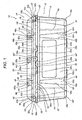
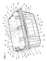
- Figure 1 is a lengthways side view of a first preferred embodiment of the container according to the present invention;
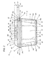
- Figure 2 is an end side view of the first preferred embodiment of the container according to the present invention;
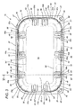
- Figure 3 is a top view of the first preferred embodiment of the container according to the present invention, showing the lid in particular;
- Figure 4 is a top view of the first preferred embodiment of the container according to the present invention, showing the container body in particular;
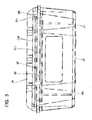
- Figure 5 is a lengthways side view showing the side with the hinge that joins the lid to the container body;
- Figure 6 is a cross section, through the line VI-VI of Figure 3, with an enlarged detail of the same cross section of the first preferred embodiment of the container according to the present invention;
- Figure 7 is a perspective view of the first preferred embodiment of the container according to the present invention;
- Figure 8 is a perspective view of a second preferred embodiment of the container according to the present invention;
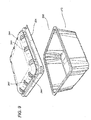
- Figure 9 is a perspective view of a third preferred embodiment of the container according to the present invention;
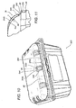
- Figure 10 is a perspective view of a fourth preferred embodiment of the container according to the present invention;
- Figure 11 is a cross section of an enlarged detail, similar to that of Figure 6, of the fourth preferred embodiment of the container according to the present invention.
- With reference to the accompanying drawings, the first preferred
embodiment 10 of the container according to the present invention is made of transparent plastic material, in particular PET, and comprises an open-top container body 12, having a plurality of side walls, labelled 14, 16, 18, 20 in the drawings, and a substantially horizontal bottom, labelled 22. - The container according to the invention also comprises a
lid 24 associated with thecontainer body 12 in such a way as to close it and in turn comprising correspondingshort side walls horizontal top 34 forming part of the lid. - The curved connecting walls, labelled 36, 38, 40, 42 in the accompanying drawings, extend along the sides of the lid according to the directrices of a corresponding cylindrical surface, that is to say, in such a way as to form a sector of a cylindrical surface, which joins the side walls of the lid to the
horizontal top 34 of the lid. - As illustrated, the connecting walls of the
lid 24 comprise a plurality of ribs, collectively labelled 44. - Advantageously, the shape of the
ribs 44 includes acurved portion 44a which is recessed or indented relative to the respective curved connectingwall - The
recessed portion 44a of therib 44 is joined to the corresponding curved connectingwall portions recessed portion 44a and lying in substantially vertical planes. - The substantially vertical
stiffening portions recessed rib portion 44a and the curved connectingwall curved portions stiffening portion - The
stiffening portions - Further, the
rib 44 shaped as described above allows the product inside the container to be viewed properly since there are no corrugated or curved surfaces to distort the view of the product, as occurs with the stiffening ribs on prior art containers. - The interior of the container is ventilated by hole means 46. Advantageously, in the container according to the invention, these holes are made in the
recessed portion 44a of therib 44. - More specifically, the hole means consist of an elliptic or
oblong opening 46, whose width is approximately one third of the width of therecessed portion 44a of therib 44. Preferably, the opening is centrally positioned within the recessed portion, as shown in the drawings. - To permit good ventilation and to allow the contents of the container to be viewed properly, the
ventilation opening 46 extends for a length substantially equal to the length of therecessed portion 44a, but is slightly longer at the end of it that extends on the top of the lid. - As illustrated, the
side walls lower portion perimetric portion peripheral lip 33 of the lid. - The lower
vertical portion peripheral portion upper wall portion wall stepped portion - The
upper portions ribs 44 made on the long sides of the connecting walls of the lid, at theopenings 46. As illustrated, theribs 48 are approximately equal in width to theholes 46 and are designed to reinforce the portions in the proximity of the openings themselves. - As illustrated, the
ribs 48 comprise a flat recessedportion 48a andopposing side mouldings - Corresponding
stiffening ribs 50 are made in the lower portion of the side wall of the lid at thecurved corner portions - The
ribs 50 comprise a flat recessedportion 50a andopposing side mouldings - As illustrated,
stiffening ribs 48, similar to thewider ribs 44 made in the portions joining the top of the lid, are made in the upper portions of the side walls, at the corner portions of the lid, to coincide with theribs 50. Thus, the corners of the lid are stiffened and highly resistant. - The
numerals 35 in the drawings denote press mouldings designed to fasten the lid in the closed position and comprising protruding lock portions that snap into matching socket portions made in the container body in such a way as to close the lid and hold it in the closed position. - On the side opposite that where the press fastener
mouldings - This hinge portion, which is denoted in its entirety by the
numeral 37 in the drawings, comprises two long moulded portions having a substantially C-shaped cross section, labelled 37a, 37b and joined to each other by a horizontal strip portion, labelled 37c. - The side opposite the hinged side also comprises suitable means, denoted in their entirety by the
numerals - Further, the
portion 52 on the lid acts in conjunction with theportion 54 which protrudes upwardly from the upper edge of thelongitudinal wall 14 of the container body. - More specifically, the first engagement means 52 are made in an intermediate area of one of the lid walls and extend from a lower edge of this wall towards the upper edge of a matching wall of the container body to engage with the second engagement means 54 that protrude from the upper edge of the wall of the container body.
- Advantageously, the first engagement means on the lid take the form of
wide teeth teeth - This guarantees a secure closure and prevents the lid from sliding sideways relative to the container body.
- These teeth have convergent
lateral contact surfaces 52', 52" and 54', 54" which engage with each other. - This facilitates the insertion of the teeth into the matching tooth spaces, ensuring a snug fit that prevents sideways movements between lid and body and confers compactness and rigidity on the container according to the invention.
- Advantageously, these means for the engagement and laterally retaining the lid on the container body are made on the side walls opposite the
hinge 37 which joins the lid to the container body. Thus, the side wall of the lid rests on the matching side wall of the container body, conferring greater flexural rigidity on the lid wall and, hence, greater rigidity on the top of the lid, too. - Advantageously, the engagement and sideways retaining means comprise teeth with substantially semicircular profiles, labelled 52a, 52b, 52c, which extend downwardly from the
lower lip 33b protruding horizontally from the corresponding vertical wall of the container lid. - Matching
semicircular teeth tooth end portions central teeth semicircular teeth - As illustrated, the semicircular teeth formed on the container body fit into the semicircular spaces made by the suitably spaced
teeth - The tooth configuration described above uniformly distributes the force applied to the tooth, thus preventing excessive strain on the tooth and significantly reducing the risk of the teeth becoming deformed.
- The thickness of the contact surfaces 52', 52" and 54', 54" of the engagement teeth is such as to guarantee a good distribution of the sideways retaining action between the lid and the container body.
- As shown clearly in Figure 1, the lower teeth extend from a lateral portion of a
peripheral lip 33 of the container body, which - thanks to the engagement means 52 and 54 and to the hinge 37 - is kept slightly clear of theperipheral lip 35a of the lid, leaving an air gap S through which the product inside the container is ventilated. - According to another aspect of the invention, as illustrated in the drawings, the
upper portions side walls portions 56, which protrude from the corresponding wall and which extend from the horizontal steppedportion lower portions - The protruding
portions 56 constitute means for stiffening the side walls of the lid. - Looking in more detail at the
container body 12, it can be seen that the bottom 22 is joined to the side walls by a corresponding recessedportion side walls - The side walls of the
container body numerals - According to another advantageous aspect of the invention, the stiffening ribs on the side walls of the lid are made only at or in the proximity of these curved connecting
portions - These stiffening ribs at the corners of the container body allow the product inside to be seen clearly through the walls of the container but without weakening the structure of the container itself.
- More specifically, these corner stiffening ribs take the form of "fretting" and comprise a first, substantially flat recessed portion, labelled 60a, which is connected by ribbed portions, labelled 60b and 60c, to the adjacent portions of the side wall.
- As illustrated in the drawings, these stiffening
ribbed portions - These "fretted" ribs are made on the
long sides - The corners joining the
long sides short sides - Each of these second "fretted" ribs comprises a recessed portion, labelled 62a, which has lateral portions, labelled 62b and 62c, joining it to the adjacent portions lying in the same plane as the side walls of the container body. Again, these portions of the stiffening
ribs 62 are upwardly convergent, as illustrated. - As illustrated in the drawings, the recessed
stiffening portions lowermost section - The above features confer resistance on the container body without using vertical ribs, like those of prior art containers of similar kind, on the intermediate portions of the container body, and thus affording a clear view of the products inside the container.
- The container body further comprises stiffening portions, labelled 66, extending vertically on, and protruding from, the corresponding walls of the container on each side of the
corner ribs 62. - As illustrated in the drawings, the lid also has a top surface designed to engage with the bottom of a container placed on top of it, this top surface being bounded by an essentially quadrangular border 34' which extends at a slightly higher level than the topmost point of the connecting
portion - More specifically, as illustrated in Figure 6, the lower edge 44'a of the ribbing surfaces - only the
rib 44c being shown in Figure 6 - has a curvature radius Ri that is greater than the curvature radius Re of the upper edge 44'c of theribbing surface 44c. - As illustrated, the convexity of these edges, which define the ribbing surface, faces upwards, that is to say, it faces the outside of the container.
- More specifically, the ratio between the curvature radius Ri of the lower edge 44'a and the curvature radius Re of the upper edge 44'c advantageously ranges from 1,2 to 2 and is preferably between 1,3 and 1,8 ideally 1,5.
- Advantageously, the curvature radius Re of the upper edge 44'c ranges from 5 to 15 mm and is preferably between 7 and 13 mm, ideally 10 mm, whilst the curvature radius Ri of the lower edge 44'a ranges from 10 to 20 mm and is preferably between 12 and 18 mm, ideally 15 mm.
- More specifically, as clearly illustrated in Figure 6, which shows only the
rib 44c, each rib has a lower end that extends from the steppedportion 28d whose thickness or height is less than the maximum height or thickness h of the rib itself, whilst at the opposite end, the edges of the rib are convergent and merge with each other at the top of the lid. - Further, the width "L" of the intermediate connecting
portion 44a, extending between the first and secondside stiffening portions - Looking in more detail, the
oblong ventilation opening 46 is preferably from 4 to 8 mm wide and, ideally, has a width "l" of 5 mm. - According to another advantageous aspect, each of the corner portions 25', 27', 29', 31' has the shape of a vault connecting adjacent side walls to the transversal
top surface 34. - Advantageously, each vault-shaped corner portion 25', 27', 29', 31' has, in the horizontal plane, a curvature radius "Ro" that ranges from 14 to 20 mm and is preferably 17 mm, whilst the curvature radius "Re" of each vault-shaped corner portion 25', 27', 29', 31' in any vertical plane may range from 5 to 15 mm, preferably between 7 and 13 mm, and is, ideally, 10 mm.
- As illustrated, the vault-shaped corner portion 25' is laterally delimited by a first stiffening rib 44', made in one
portion 36 of the lid, and by asecond stiffening rib 44", made on aportion 40 adjacent (and at right angles) to the one where the first stiffening rib is made. This confers considerable rigidity on the corner portion. - Further, the height Vl of the
side walls portion - Looking in more detail, the height V'l of the lower
vertical portions vertical portions lid side walls - As illustrated, the
container body 12 has stiffening ribs on its side walls solely at the corner portions conferring structural rigidity on the container in its entirety, while at the same time providing a better view inside the container. - The stiffening ribs, made solely at the corner portions of the side walls of the
container body 12, are delimited by the verticalprotruding stiffening portions 66. - Each
rib 44 extends past the circumferential border 34' that delimits the toptransversal surface 34 and does not protrude upwards relative to this toptransversal surface 34, making it possible to obtain a rigid structure that can be made using a simplified, lower-cost mould. - Figure 8 illustrates a second
preferred embodiment 100 of the container according to the present invention, this embodiment being substantially the same as the first preferred embodiment, from which it differs in that it has a smaller number of ribs, labelled 144, the short sides of the container having only onerib 144 made in each of them. - In another embodiment, illustrated in an exploded view in Figure 9, the
lid 224 is not hinged to the container body as in the embodiments described above, but is separate from thecontainer body 212. The container, in this thirdpreferred embodiment 200, is substantially square in shape, when viewed from above, and its lid has the same number ofribs 244 on all four sides of it. - Figures 10 and 11 illustrate a fourth
preferred embodiment 300 of the container. In these illustrations, the parts of the fourth embodiment that are identical to those of the first preferred embodiment are denoted by the same reference characters. In the fourth preferred embodiment, the ribbing surfaces 344b and 344c of therib 344 on the lid start at a steppedportion 345, which extends horizontally between the space or recess defined by the ribbing surfaces 344b and 344c, starting from a substantiallyvertical extension 328e of the horizontal steppedportion 28d of the lid. This confers greater rigidity on the part at the base of the ribbing, making the container as a whole more resistant to vertical loads. - The first preferred embodiment of the container illustrated is approximately 187,5 mm long, 118 mm wide and 90 mm high. The second preferred embodiment of the container illustrated is approximately 127,5 mm long, 96,5 mm wide and 80 mm high. In the third preferred embodiment of the container illustrated, the length of the sides is approximately 186 mm and the height is 114 mm. Containers with dimensions other than these are, however, imaginable. The container according to the present invention is made by moulding of plastic material, especially by thermoforming.
- It will be understood that the invention can be subject to modifications and variations without thereby departing from the scope of the inventive concept. Moreover, all the details of the invention may be substituted by technically equivalent elements.
Claims (50)
- A product container (10) in particular for fruit or vegetables or similar products, the container comprising a container body (12) and a lid (24) and being characterised in that the container body (12) or the lid (24), and especially the latter, comprises at least one rib (44), the rib (44) having at least one stiffening portion (44b, 44c) that forms a ribbing surface which extends between a lower edge (44'a) and an upper edge (44'c) in such a way that the width, or distance between these edges (44'a, 44'c) is at its maximum at an intermediate point of the stiffening portion (44b, 44c).
- The container according to claim 1 or according to the preamble to claim 1, characterised in that the container body (12) or the lid (24), and especially the latter, comprises at least one rib (44), the rib (44) having first and second side stiffening portions (44b, 44c) opposite each other, forming a ribbing surface which extends between a lower edge (44'a) and an upper edge (44'c), with an intermediate connecting portion (44a) extending between the first and second side stiffening portions (44b, 44c).
- The container according to either of the foregoing claims, characterised in that the rib (44) has an intermediate recessed connecting portion (44a) extending between the first and second side stiffening portions (44b, 44c).
- The container according to any of the foregoing claims, characterised in that the rib (44) has an intermediate portion (44a) extending along a curved profile.
- The container according to any of the foregoing claims, where the container body and the lid comprise respective side walls (14, 16, 18, 20 or 26, 28, 30, 32) and a respective transversal bottom surface (22) or top transversal surface (24), characterised in that the container body (12) or the lid (24), and especially the latter, comprises side walls (26, 28, 30, 32) that are each connected by a corresponding connecting wall (36, 38, 40, 42) to a transversal surface (34).
- The container according to claim 5, characterised in that the connecting wall (36, 38, 40, 42) has a curved profile.
- The container according to any of the foregoing claims, characterised in that the ribbing surface (44b, 44c) of the stiffening portion extends in a substantially vertical direction.
- The container according to any of the foregoing claims, characterised in that the rib (44) is made on the connecting wall (36, 38, 40, 42).
- The container according to any of the foregoing claims, characterised in that the ribbing surface (44b, 44c) has an edge (44'c) joining it to the connecting wall (36, 38, 40, 42).
- The container according to any of the foregoing claims, characterised in that the ribbing surface (44b, 44c) has an edge (44'a) joining it to the intermediate portion (44a).
- The container according to claim 9 or 10, characterised in that the upper edge (44'c) of the ribbing surface (44c) is curved.
- The container according to any of the foregoing claims from 9 to 11, characterised in that the lower edge (44'a) of the ribbing surface (44c) is curved.
- The container according to any of the foregoing claims or according to the preamble to claim 1, characterised in that it comprises at least one stiffening or ribbing portion (44b, 44c) extending between an upper edge (44'c) having a curvature radius (Re), and a lower edge (44'a) having a curvature radius (Ri), where the curvature radius (Ri) of the lower edge (44'a) is greater than the curvature radius (Re) of the upper edge (44'c) of the ribbing surface (44c).
- The container according to claim 13, characterised in that the ratio between the curvature radius (Ri) of the lower edge (44'a) and the curvature radius (Re) of the upper edge (44'c) may range from 1,2 to 2, and is preferably between 1,3 and 1,8 and ideally 1,5.
- The container according to any of the foregoing claims, characterised in that the curvature radius (Re) of the upper edge (44'c) may range from 5 to 15 mm, and is preferably between 7 and 13 mm and ideally 10 mm.
- The container according to any of the foregoing claims, characterised in that the curvature radius (Ri) of the lower edge (44'a) may range from 10 to 20 mm, and is preferably between 12 and 18 mm and ideally 15 mm.
- The container according to any of the foregoing claims, characterised in that the width "L" of the intermediate connecting portion (44a), extending between the first and second side stiffening portions (44b, 44c), ranges from 4 to 18 mm, is preferably between 8 and 14 mm and, ideally, 12 mm.
- The container according to any of the foregoing claims or according to the preamble to claim 1, characterised in that the container body (12) or the lid (24), and especially the latter, has openings (46) made in it to ventilate the inside of the container.
- The container according to claim 18, characterised in that the openings (46) for ventilating the inside of the container are made in the connecting wall (36, 38, 40, 42).
- The container according to claim 18 or 19, characterised in that the openings (46) for ventilating the inside of the container are made in the intermediate portion (44a) of the rib (44).
- The container according to any of the foregoing claims from 10 to 20, characterised in that the openings (46) consist of at least one oblong or elliptic opening (46).
- The container according to any of the foregoing claims from 18 to 21, characterised in that the openings (46) extend onto the transversal surface (34) of the corresponding element.
- The container according to any of the foregoing claims from 18 to 22, characterised in that the openings (46) start at the corresponding side wall (26, 28, 30, 32).
- The container according to any of the foregoing claims from 18 to 23, characterised in that the length of the ventilation opening (46) is approximately equal to the length of the intermediate portion (44a).
- The container according to any of the foregoing claims or according to the preamble to claim 1, characterised in that the container body (12) or the lid (24), and especially the latter, has at least one corner portion (25', 27', 29', 31') having the shape of a vault.
- The container according to claim 25, characterised in that the vault-shaped corner portion (25') is laterally delimited by a first stiffening rib (44') made on one side (36) of the container.
- The container according to claim 25 or 26, characterised in that the vault-shaped corner portion (25') is laterally delimited by at least one second stiffening rib (44"), made on a side (40) adjacent to the one where the first stiffening rib is made.
- The container according to any of the foregoing claims or according to the preamble to claim 1, characterised in that at least one of the side walls (26, 28, 30, 32) of at least the container body (12) or the lid (24), or of both of them, and especially of the lid (24) comprises a respective lower vertical portion (26a, 28a, 30a, 32a), which is integral with a lower peripheral lip or horizontal perimetric portion (33a, 33b, 33c, 33d) of the lid.
- The container according to claim 28, characterised in that at least one of the side walls (26, 28, 30, 32) of at least the container body (12) or the lid (24), or of both of them, and especially of the lid (24) comprises a respective upper wall portion (26c, 28c, 30c, 32c), which extends vertically and is connected by a peripheral stepped portion (26b, 28b, 30b, 32b) that is substantially horizontal, to the corresponding lower vertical portion (26a, 28a, 30a, 32a).
- The container according to claim 29, characterised in that the upper wall portion (26c, 28c, 30c, 32c), which extends vertically, is connected by a substantially horizontal stepped portion (26d, 28d, 30d, 32d), to the corresponding upper connecting wall (36, 38, 40, 42).
- The container according to claim 29 or 30, characterised in that the height (Vl) of the side walls (26, 28, 30, 32) is less than the height (Vr) of the connecting portion (36, 38, 40, 42).
- The container according to any of the foregoing claims from 29 to 31, characterised in that the height (V'l) of the lower vertical portions (26a, 28a, 30a, 32a) and the height (V"l) of the upper vertical wall portions (26c, 28c, 30c, 32c) of the lid side walls (26, 28, 30, 32) are substantially the same.
- The container according to any of the foregoing claims, characterised in that the upper portions (26c, 28c) of the side walls have other stiffening ribs (48) made in them at the ribs (44) in the connecting walls.
- The container according to any of the foregoing claims or according to the preamble to claim 1, characterised in that there is at least one curved horizontal connecting portion (25, 27, 29, 31) between adjacent side walls (26, 28, 30, 32).
- The container according to claim 34, characterised in that corresponding stiffening ribs (50) are made in the lower portions of the side walls of the lid at the curved horizontal connecting portions (25, 27, 29, 31) of these side walls.
- The container according to any of the foregoing claims or according to the preamble to claim 1, characterised in that the container body (12) or the lid (24), and especially the latter, comprises, in a corresponding side wall of it (26, 28, 30, 32), at least one first stiffening portion (56 or 66), which laterally delimits a corresponding curved horizontal connecting portion (25, 27, 29, 31) between adjacent side walls (26, 28, 30, 32).
- The container according to claim 36, characterised in that the curved horizontal connecting portion (25, 27, 29, 31) between adjacent side walls (26, 28, 30, 32) is laterally delimited by at least one second stiffening portion (56 or 66), made on a side (40) adjacent to the one where the first stiffening rib is made.
- The container according to claim 36 or 37, characterised in that the stiffening portion (56, 66) made in the side wall (26, 28, 30, 32) protrudes outwards from the corresponding wall.
- The container according to any of the foregoing claims or according to the preamble to claim 1, characterised in that first engagement means (52) are made in an intermediate area of one of the lid walls and extend from a lower edge of this wall towards the upper edge of a matching wall of the container body to engage with matching second engagement means (54) that protrude from the upper edge of the wall of the container body; and also characterised in that the first engagement means on the lid take the form of wide teeth (52a, 52b, 52c) which fit into matching spaces between teeth (54a, 54b, 54c, 54d) of the second engagement means on the container body.
- The container according to claim 39, characterised in that the teeth have convergent lateral contact surfaces (52', 52" and 54', 54") which engage with each other.
- The container according to claim 39 or 40, characterised in that the means (52, 54) for engaging and laterally retaining the lid on the container body are made on the side walls opposite the hinge (37) which joins the lid to the container body.
- The container according to any of the foregoing claims from 39 to 41, characterised in that the engagement and laterally retaining means comprise arc-shaped teeth (52a, 52b, 52c), extending downwardly from the lid, and matching toothed portions (54a, 54b, 54c, 54b), extending along the upper edge of the corresponding wall of the container body.
- The container (10) according to any of the foregoing claims or according to the preamble to claim 1, characterised in that there are stiffening ribs (60, 62) at the corners of the container body; in that the side walls (14, 16, 18, 20) of the container body comprise corresponding recessed portions (14a, 16a, 18a, 20a) forming a stiffening base joining the side walls (14, 16, 18, 20) to the bottom (22) of the container body; and in that the stiffening base portions (14a, 16a, 18a, 20a) of the container body short stiffening ribs (60', 62') at the ribs (60, 62) made at the corners of the side walls (14, 16, 18, 20) of the container body.
- The container according to any of the foregoing claims or according to the preamble to claim 1, characterised in that the container body (12) has stiffening ribs on its side walls solely at its corner portions.
- The container according to claim 44, characterised in that the stiffening ribs on the side walls solely at the corner portions of the container body (12) are laterally delimited by the vertical protruding stiffening portions (66).
- The container according to any of the foregoing claims or according to the preamble to claim 1, characterised in that the top surface (34) has a perimetric border (34'), which extends at a slightly higher level than the topmost point of the connecting portion (36, 38, 40, 42).
- The container according to any of the foregoing claims or according to the preamble to claim 1, characterised in that the ribbing surfaces (344b, 344c) of the rib (344) start at a stepped portion (345), which extends horizontally between the space or recess defined by the ribbing surfaces (344b, 344c), starting from a substantially vertical extension (328e) of the horizontal lip (28d) from which the connecting portion (36, 38, 40, 42) extends.
- A container body (12) according to any of the foregoing claims.
- A lid (24) according to any of the foregoing claims.
- Use of a container or parts of it, made according to any of the foregoing claims, for packaging food products, in particular fruit or vegetables.
Applications Claiming Priority (3)
| Application Number | Priority Date | Filing Date | Title |
|---|---|---|---|
| IT2002BO000132A ITBO20020132A1 (en) | 2002-03-20 | 2002-03-20 | BASKET FOR THE CONTAINMENT OF PRODUCTS, IN PARTICULAR OF FRUITS AND VEGETABLES |
| ITBO20020132 | 2002-03-20 | ||
| EP03425170A EP1336569B1 (en) | 2002-03-20 | 2003-03-19 | A product container, in particular for fruit or vegetables |
Related Parent Applications (2)
| Application Number | Title | Priority Date | Filing Date |
|---|---|---|---|
| EP03425170A Division EP1336569B1 (en) | 2002-03-20 | 2003-03-19 | A product container, in particular for fruit or vegetables |
| EP03425170.2 Division | 2003-03-19 |
Publications (3)
| Publication Number | Publication Date |
|---|---|
| EP1526077A2 true EP1526077A2 (en) | 2005-04-27 |
| EP1526077A3 EP1526077A3 (en) | 2005-08-03 |
| EP1526077B1 EP1526077B1 (en) | 2012-05-09 |
Family
ID=11439978
Family Applications (2)
| Application Number | Title | Priority Date | Filing Date |
|---|---|---|---|
| EP03425170A Expired - Lifetime EP1336569B1 (en) | 2002-03-20 | 2003-03-19 | A product container, in particular for fruit or vegetables |
| EP05100660A Expired - Lifetime EP1526077B1 (en) | 2002-03-20 | 2003-03-19 | A product container, in particular for fruit or vegetables |
Family Applications Before (1)
| Application Number | Title | Priority Date | Filing Date |
|---|---|---|---|
| EP03425170A Expired - Lifetime EP1336569B1 (en) | 2002-03-20 | 2003-03-19 | A product container, in particular for fruit or vegetables |
Country Status (5)
| Country | Link |
|---|---|
| EP (2) | EP1336569B1 (en) |
| AT (2) | ATE556944T1 (en) |
| DE (1) | DE60300723D1 (en) |
| ES (1) | ES2390493T3 (en) |
| IT (1) | ITBO20020132A1 (en) |
Cited By (2)
| Publication number | Priority date | Publication date | Assignee | Title |
|---|---|---|---|---|
| EP2275358A3 (en) * | 2009-07-17 | 2011-06-08 | ISAP Packaging S.P.A. | A process and plant for obtaining a container body particurlarly suitable for packaging food products |
| IT201700005771A1 (en) * | 2017-01-19 | 2018-07-19 | Corte Parma Alimentare S R L | CONTAINER |
Families Citing this family (21)
| Publication number | Priority date | Publication date | Assignee | Title |
|---|---|---|---|---|
| ITBO20050196A1 (en) * | 2005-03-25 | 2006-09-26 | Infia Srl | CONTAINER FOR THE PACKAGING OF PRODUCTS, IN PARTICULAR OF FRUIT AND VEGETABLE PRODUCTS |
| US7748560B2 (en) | 2006-07-11 | 2010-07-06 | Taylor Fresh Vegetables, Inc. | Atmosphere controlled packaging for fresh foodstuffs |
| US7748561B2 (en) | 2006-07-11 | 2010-07-06 | Taylor Fresh Vegetables, Inc. | Atmosphere controlled packaging for fresh foodstuffs |
| US8511499B2 (en) | 2007-12-18 | 2013-08-20 | Abbott Laboratories | Container |
| EP2117949A4 (en) | 2006-12-27 | 2011-01-12 | Abbott Lab | Container |
| US8167166B2 (en) | 2007-11-23 | 2012-05-01 | Peninsula Packaging, Llc | Container |
| US8261933B2 (en) | 2007-11-28 | 2012-09-11 | Peninsula Packaging, Llc | Container |
| US8091731B2 (en) | 2007-11-28 | 2012-01-10 | Peninsula Packaging, Llc | Container |
| US8627981B2 (en) | 2009-06-05 | 2014-01-14 | Abbott Laboratories | Container |
| US8469223B2 (en) | 2009-06-05 | 2013-06-25 | Abbott Laboratories | Strength container |
| US8608008B2 (en) | 2010-08-26 | 2013-12-17 | Dart Container Corporation | Tamper evident container |
| US9624009B2 (en) | 2010-08-26 | 2017-04-18 | Dart Container Corporation | Tamper evident container |
| USD675517S1 (en) | 2011-07-29 | 2013-02-05 | Dart Container Corporation | Container |
| IN2014DN08897A (en) | 2012-04-27 | 2015-05-22 | Abbott Lab | |
| USD733320S1 (en) | 2013-04-26 | 2015-06-30 | Abbott Laboratories | Container |
| FR3032086B1 (en) * | 2015-01-29 | 2017-08-18 | Buvette | ABREUVOIR WITH ENHANCED WALLS |
| US10351310B2 (en) | 2016-10-28 | 2019-07-16 | Genpak, Llc | Tamper-evident container with a bump near a tabbed hinge |
| US10220985B2 (en) | 2016-10-28 | 2019-03-05 | Genpak, Llc | Tamper-evident container with a tabbed hinge |
| US10889413B2 (en) | 2016-10-28 | 2021-01-12 | Genpak, Llc | Tamper-evident container with a tab extending beyond a hinge |
| US10894635B2 (en) | 2016-10-28 | 2021-01-19 | Genpak, Llc | Tamper-evident container with a wide tab extending beyond a hinge |
| US10723523B2 (en) | 2017-01-10 | 2020-07-28 | Fabri-Kal Corporation | Tamper evident container having bonded tab |
Citations (4)
| Publication number | Priority date | Publication date | Assignee | Title |
|---|---|---|---|---|
| US3795360A (en) * | 1971-12-02 | 1974-03-05 | Safeway Stores | Cover for basket-type container and combination thereof |
| US3837526A (en) * | 1972-08-31 | 1974-09-24 | Kirkhof Mfg Corp | Cover for produce carton |
| US4113095A (en) * | 1976-11-26 | 1978-09-12 | Van Dorn Company | Tray-type processed food containers |
| FR2399359A1 (en) * | 1977-08-05 | 1979-03-02 | Gatrun Anstalt | Mould for forming containers with partially hollow walls - using mould inserts to define internal channels |
Family Cites Families (4)
| Publication number | Priority date | Publication date | Assignee | Title |
|---|---|---|---|---|
| NL6909149A (en) * | 1968-06-26 | 1969-12-30 | ||
| JPH05213331A (en) * | 1992-01-29 | 1993-08-24 | Asahi Chem Ind Co Ltd | Fit-in type container made of expanded synthetic resin |
| GB2339766A (en) * | 1998-07-23 | 2000-02-09 | Infia Srl | A container suitable for fruit and vegetables and the like |
| US6029803A (en) * | 1999-01-14 | 2000-02-29 | Ovadia Corp. | Display and storage box with interlocking, friction fitting halves |
-
2002
- 2002-03-20 IT IT2002BO000132A patent/ITBO20020132A1/en unknown
-
2003
- 2003-03-19 EP EP03425170A patent/EP1336569B1/en not_active Expired - Lifetime
- 2003-03-19 AT AT05100660T patent/ATE556944T1/en active
- 2003-03-19 AT AT03425170T patent/ATE296760T1/en not_active IP Right Cessation
- 2003-03-19 DE DE60300723T patent/DE60300723D1/en not_active Expired - Lifetime
- 2003-03-19 EP EP05100660A patent/EP1526077B1/en not_active Expired - Lifetime
- 2003-03-19 ES ES05100660T patent/ES2390493T3/en not_active Expired - Lifetime
Patent Citations (4)
| Publication number | Priority date | Publication date | Assignee | Title |
|---|---|---|---|---|
| US3795360A (en) * | 1971-12-02 | 1974-03-05 | Safeway Stores | Cover for basket-type container and combination thereof |
| US3837526A (en) * | 1972-08-31 | 1974-09-24 | Kirkhof Mfg Corp | Cover for produce carton |
| US4113095A (en) * | 1976-11-26 | 1978-09-12 | Van Dorn Company | Tray-type processed food containers |
| FR2399359A1 (en) * | 1977-08-05 | 1979-03-02 | Gatrun Anstalt | Mould for forming containers with partially hollow walls - using mould inserts to define internal channels |
Cited By (2)
| Publication number | Priority date | Publication date | Assignee | Title |
|---|---|---|---|---|
| EP2275358A3 (en) * | 2009-07-17 | 2011-06-08 | ISAP Packaging S.P.A. | A process and plant for obtaining a container body particurlarly suitable for packaging food products |
| IT201700005771A1 (en) * | 2017-01-19 | 2018-07-19 | Corte Parma Alimentare S R L | CONTAINER |
Also Published As
| Publication number | Publication date |
|---|---|
| EP1336569B1 (en) | 2005-06-01 |
| ATE296760T1 (en) | 2005-06-15 |
| ITBO20020132A1 (en) | 2003-09-22 |
| ATE556944T1 (en) | 2012-05-15 |
| EP1336569A2 (en) | 2003-08-20 |
| EP1526077B1 (en) | 2012-05-09 |
| ITBO20020132A0 (en) | 2002-03-20 |
| EP1526077A3 (en) | 2005-08-03 |
| DE60300723D1 (en) | 2005-07-07 |
| EP1336569A3 (en) | 2003-10-22 |
| ES2390493T3 (en) | 2012-11-13 |
Similar Documents
| Publication | Publication Date | Title |
|---|---|---|
| EP1336569B1 (en) | A product container, in particular for fruit or vegetables | |
| US7114630B2 (en) | Tray lid | |
| US7284673B2 (en) | Locking structure for hinged container | |
| CA2202700C (en) | Latch mechanism for a plastic container | |
| US5515993A (en) | Hinged semi-rigid container having wall stiffening means | |
| EP0124305B1 (en) | Nestable container suitable for containing structured paint | |
| US9643757B2 (en) | Method of merchandising lids and vessels | |
| US4572374A (en) | Container | |
| US5372257A (en) | Stackable load bearing tray | |
| US4742934A (en) | Container structure | |
| EP1705128B1 (en) | Container for the packaging of products, more specifically for fruit and vegetable products | |
| US4364489A (en) | Container lid | |
| US5992673A (en) | Reusable produce crate | |
| EP0299657A1 (en) | Container | |
| GB2129401A (en) | Stacking/nesting containers | |
| JP4105186B2 (en) | Container lid | |
| US6478181B1 (en) | Shrinkable tray with attachable lids | |
| US10138031B2 (en) | Pivoting cover for a container | |
| US8056758B2 (en) | Non-cylindrical container and lid | |
| JP5425580B2 (en) | Logistics container | |
| US6513675B1 (en) | Food container with rigid base plate | |
| CN210479525U (en) | Container for packaging | |
| JP6250352B2 (en) | Logistics container | |
| JP4945335B2 (en) | Plastic container lid | |
| EP0446026A2 (en) | Container |
Legal Events
| Date | Code | Title | Description |
|---|---|---|---|
| PUAI | Public reference made under article 153(3) epc to a published international application that has entered the european phase |
Free format text: ORIGINAL CODE: 0009012 |
|
| AC | Divisional application: reference to earlier application |
Ref document number: 1336569 Country of ref document: EP Kind code of ref document: P |
|
| AK | Designated contracting states |
Kind code of ref document: A2 Designated state(s): AT BE BG CH CY CZ DE DK EE ES FI FR GB GR HU IE IT LI LU MC NL PT RO SE SI SK TR |
|
| AX | Request for extension of the european patent |
Extension state: AL MK |
|
| PUAL | Search report despatched |
Free format text: ORIGINAL CODE: 0009013 |
|
| AK | Designated contracting states |
Kind code of ref document: A3 Designated state(s): AT BE BG CH CY CZ DE DK EE ES FI FR GB GR HU IE IT LI LU MC NL PT RO SE SI SK TR |
|
| AX | Request for extension of the european patent |
Extension state: AL MK |
|
| 17P | Request for examination filed |
Effective date: 20060116 |
|
| AKX | Designation fees paid |
Designated state(s): AT BE BG CH CY CZ DE DK EE ES FI FR GB GR HU IE IT LI LU MC NL PT RO SE SI SK TR |
|
| 17Q | First examination report despatched |
Effective date: 20090810 |
|
| GRAP | Despatch of communication of intention to grant a patent |
Free format text: ORIGINAL CODE: EPIDOSNIGR1 |
|
| GRAS | Grant fee paid |
Free format text: ORIGINAL CODE: EPIDOSNIGR3 |
|
| GRAA | (expected) grant |
Free format text: ORIGINAL CODE: 0009210 |
|
| AC | Divisional application: reference to earlier application |
Ref document number: 1336569 Country of ref document: EP Kind code of ref document: P |
|
| AK | Designated contracting states |
Kind code of ref document: B1 Designated state(s): AT BE BG CH CY CZ DE DK EE ES FI FR GB GR HU IE IT LI LU MC NL PT RO SE SI SK TR |
|
| REG | Reference to a national code |
Ref country code: GB Ref legal event code: FG4D |
|
| REG | Reference to a national code |
Ref country code: AT Ref legal event code: REF Ref document number: 556944 Country of ref document: AT Kind code of ref document: T Effective date: 20120515 Ref country code: CH Ref legal event code: EP |
|
| REG | Reference to a national code |
Ref country code: IE Ref legal event code: FG4D |
|
| REG | Reference to a national code |
Ref country code: DE Ref legal event code: R096 Ref document number: 60340935 Country of ref document: DE Effective date: 20120705 |
|
| REG | Reference to a national code |
Ref country code: NL Ref legal event code: VDEP Effective date: 20120509 |
|
| PG25 | Lapsed in a contracting state [announced via postgrant information from national office to epo] |
Ref country code: CY Free format text: LAPSE BECAUSE OF FAILURE TO SUBMIT A TRANSLATION OF THE DESCRIPTION OR TO PAY THE FEE WITHIN THE PRESCRIBED TIME-LIMIT Effective date: 20120509 Ref country code: FI Free format text: LAPSE BECAUSE OF FAILURE TO SUBMIT A TRANSLATION OF THE DESCRIPTION OR TO PAY THE FEE WITHIN THE PRESCRIBED TIME-LIMIT Effective date: 20120509 Ref country code: SE Free format text: LAPSE BECAUSE OF FAILURE TO SUBMIT A TRANSLATION OF THE DESCRIPTION OR TO PAY THE FEE WITHIN THE PRESCRIBED TIME-LIMIT Effective date: 20120509 |
|
| REG | Reference to a national code |
Ref country code: ES Ref legal event code: FG2A Ref document number: 2390493 Country of ref document: ES Kind code of ref document: T3 Effective date: 20121113 |
|
| REG | Reference to a national code |
Ref country code: AT Ref legal event code: MK05 Ref document number: 556944 Country of ref document: AT Kind code of ref document: T Effective date: 20120509 |
|
| PG25 | Lapsed in a contracting state [announced via postgrant information from national office to epo] |
Ref country code: GR Free format text: LAPSE BECAUSE OF FAILURE TO SUBMIT A TRANSLATION OF THE DESCRIPTION OR TO PAY THE FEE WITHIN THE PRESCRIBED TIME-LIMIT Effective date: 20120810 Ref country code: SI Free format text: LAPSE BECAUSE OF FAILURE TO SUBMIT A TRANSLATION OF THE DESCRIPTION OR TO PAY THE FEE WITHIN THE PRESCRIBED TIME-LIMIT Effective date: 20120509 Ref country code: PT Free format text: LAPSE BECAUSE OF FAILURE TO SUBMIT A TRANSLATION OF THE DESCRIPTION OR TO PAY THE FEE WITHIN THE PRESCRIBED TIME-LIMIT Effective date: 20120910 |
|
| PG25 | Lapsed in a contracting state [announced via postgrant information from national office to epo] |
Ref country code: BE Free format text: LAPSE BECAUSE OF FAILURE TO SUBMIT A TRANSLATION OF THE DESCRIPTION OR TO PAY THE FEE WITHIN THE PRESCRIBED TIME-LIMIT Effective date: 20120509 |
|
| PG25 | Lapsed in a contracting state [announced via postgrant information from national office to epo] |
Ref country code: DK Free format text: LAPSE BECAUSE OF FAILURE TO SUBMIT A TRANSLATION OF THE DESCRIPTION OR TO PAY THE FEE WITHIN THE PRESCRIBED TIME-LIMIT Effective date: 20120509 Ref country code: AT Free format text: LAPSE BECAUSE OF FAILURE TO SUBMIT A TRANSLATION OF THE DESCRIPTION OR TO PAY THE FEE WITHIN THE PRESCRIBED TIME-LIMIT Effective date: 20120509 Ref country code: SK Free format text: LAPSE BECAUSE OF FAILURE TO SUBMIT A TRANSLATION OF THE DESCRIPTION OR TO PAY THE FEE WITHIN THE PRESCRIBED TIME-LIMIT Effective date: 20120509 Ref country code: EE Free format text: LAPSE BECAUSE OF FAILURE TO SUBMIT A TRANSLATION OF THE DESCRIPTION OR TO PAY THE FEE WITHIN THE PRESCRIBED TIME-LIMIT Effective date: 20120509 Ref country code: CZ Free format text: LAPSE BECAUSE OF FAILURE TO SUBMIT A TRANSLATION OF THE DESCRIPTION OR TO PAY THE FEE WITHIN THE PRESCRIBED TIME-LIMIT Effective date: 20120509 Ref country code: RO Free format text: LAPSE BECAUSE OF FAILURE TO SUBMIT A TRANSLATION OF THE DESCRIPTION OR TO PAY THE FEE WITHIN THE PRESCRIBED TIME-LIMIT Effective date: 20120509 Ref country code: NL Free format text: LAPSE BECAUSE OF FAILURE TO SUBMIT A TRANSLATION OF THE DESCRIPTION OR TO PAY THE FEE WITHIN THE PRESCRIBED TIME-LIMIT Effective date: 20120509 |
|
| PLBE | No opposition filed within time limit |
Free format text: ORIGINAL CODE: 0009261 |
|
| STAA | Information on the status of an ep patent application or granted ep patent |
Free format text: STATUS: NO OPPOSITION FILED WITHIN TIME LIMIT |
|
| 26N | No opposition filed |
Effective date: 20130212 |
|
| REG | Reference to a national code |
Ref country code: DE Ref legal event code: R097 Ref document number: 60340935 Country of ref document: DE Effective date: 20130212 |
|
| PG25 | Lapsed in a contracting state [announced via postgrant information from national office to epo] |
Ref country code: BG Free format text: LAPSE BECAUSE OF FAILURE TO SUBMIT A TRANSLATION OF THE DESCRIPTION OR TO PAY THE FEE WITHIN THE PRESCRIBED TIME-LIMIT Effective date: 20120809 |
|
| PG25 | Lapsed in a contracting state [announced via postgrant information from national office to epo] |
Ref country code: MC Free format text: LAPSE BECAUSE OF NON-PAYMENT OF DUE FEES Effective date: 20130331 |
|
| REG | Reference to a national code |
Ref country code: CH Ref legal event code: PL |
|
| REG | Reference to a national code |
Ref country code: IE Ref legal event code: MM4A |
|
| REG | Reference to a national code |
Ref country code: DE Ref legal event code: R119 Ref document number: 60340935 Country of ref document: DE Effective date: 20131001 |
|
| PG25 | Lapsed in a contracting state [announced via postgrant information from national office to epo] |
Ref country code: DE Free format text: LAPSE BECAUSE OF NON-PAYMENT OF DUE FEES Effective date: 20131001 Ref country code: LI Free format text: LAPSE BECAUSE OF NON-PAYMENT OF DUE FEES Effective date: 20130331 Ref country code: CH Free format text: LAPSE BECAUSE OF NON-PAYMENT OF DUE FEES Effective date: 20130331 Ref country code: IE Free format text: LAPSE BECAUSE OF NON-PAYMENT OF DUE FEES Effective date: 20130319 |
|
| PG25 | Lapsed in a contracting state [announced via postgrant information from national office to epo] |
Ref country code: TR Free format text: LAPSE BECAUSE OF FAILURE TO SUBMIT A TRANSLATION OF THE DESCRIPTION OR TO PAY THE FEE WITHIN THE PRESCRIBED TIME-LIMIT Effective date: 20120509 |
|
| PG25 | Lapsed in a contracting state [announced via postgrant information from national office to epo] |
Ref country code: LU Free format text: LAPSE BECAUSE OF NON-PAYMENT OF DUE FEES Effective date: 20130319 Ref country code: HU Free format text: LAPSE BECAUSE OF FAILURE TO SUBMIT A TRANSLATION OF THE DESCRIPTION OR TO PAY THE FEE WITHIN THE PRESCRIBED TIME-LIMIT; INVALID AB INITIO Effective date: 20030319 |
|
| REG | Reference to a national code |
Ref country code: FR Ref legal event code: PLFP Year of fee payment: 14 |
|
| REG | Reference to a national code |
Ref country code: FR Ref legal event code: PLFP Year of fee payment: 15 |
|
| REG | Reference to a national code |
Ref country code: FR Ref legal event code: PLFP Year of fee payment: 16 |
|
| PGFP | Annual fee paid to national office [announced via postgrant information from national office to epo] |
Ref country code: GB Payment date: 20220322 Year of fee payment: 20 |
|
| PGFP | Annual fee paid to national office [announced via postgrant information from national office to epo] |
Ref country code: FR Payment date: 20220325 Year of fee payment: 20 |
|
| PGFP | Annual fee paid to national office [announced via postgrant information from national office to epo] |
Ref country code: IT Payment date: 20220330 Year of fee payment: 20 Ref country code: ES Payment date: 20220418 Year of fee payment: 20 |
|
| REG | Reference to a national code |
Ref country code: GB Ref legal event code: PE20 Expiry date: 20230318 |
|
| REG | Reference to a national code |
Ref country code: ES Ref legal event code: FD2A Effective date: 20230427 |
|
| PG25 | Lapsed in a contracting state [announced via postgrant information from national office to epo] |
Ref country code: GB Free format text: LAPSE BECAUSE OF EXPIRATION OF PROTECTION Effective date: 20230318 |
|
| PG25 | Lapsed in a contracting state [announced via postgrant information from national office to epo] |
Ref country code: ES Free format text: LAPSE BECAUSE OF EXPIRATION OF PROTECTION Effective date: 20230320 |