EP1526038B1 - Dual-function headlamp device for vehicle - Google Patents
Dual-function headlamp device for vehicle Download PDFInfo
- Publication number
- EP1526038B1 EP1526038B1 EP03292622A EP03292622A EP1526038B1 EP 1526038 B1 EP1526038 B1 EP 1526038B1 EP 03292622 A EP03292622 A EP 03292622A EP 03292622 A EP03292622 A EP 03292622A EP 1526038 B1 EP1526038 B1 EP 1526038B1
- Authority
- EP
- European Patent Office
- Prior art keywords
- light
- filtering means
- lens
- intermediate lens
- light beam
- Prior art date
- Legal status (The legal status is an assumption and is not a legal conclusion. Google has not performed a legal analysis and makes no representation as to the accuracy of the status listed.)
- Expired - Lifetime
Links
- 238000001914 filtration Methods 0.000 claims abstract description 42
- 239000006185 dispersion Substances 0.000 claims abstract description 8
- 230000004438 eyesight Effects 0.000 claims description 9
- 229910052736 halogen Inorganic materials 0.000 claims description 3
- 150000002367 halogens Chemical class 0.000 claims description 3
- 230000003287 optical effect Effects 0.000 description 7
- 230000005855 radiation Effects 0.000 description 5
- 238000001228 spectrum Methods 0.000 description 4
- JEIPFZHSYJVQDO-UHFFFAOYSA-N iron(III) oxide Inorganic materials O=[Fe]O[Fe]=O JEIPFZHSYJVQDO-UHFFFAOYSA-N 0.000 description 3
- 241000287107 Passer Species 0.000 description 2
- 241001080024 Telles Species 0.000 description 2
- 230000001588 bifunctional effect Effects 0.000 description 2
- 230000008859 change Effects 0.000 description 2
- 238000005286 illumination Methods 0.000 description 2
- 230000004048 modification Effects 0.000 description 2
- 238000012986 modification Methods 0.000 description 2
- 229920000297 Rayon Polymers 0.000 description 1
- SEQDDYPDSLOBDC-UHFFFAOYSA-N Temazepam Chemical compound N=1C(O)C(=O)N(C)C2=CC=C(Cl)C=C2C=1C1=CC=CC=C1 SEQDDYPDSLOBDC-UHFFFAOYSA-N 0.000 description 1
- 238000004026 adhesive bonding Methods 0.000 description 1
- 239000004020 conductor Substances 0.000 description 1
- 238000009792 diffusion process Methods 0.000 description 1
- 238000006073 displacement reaction Methods 0.000 description 1
- 239000003292 glue Substances 0.000 description 1
- 238000002329 infrared spectrum Methods 0.000 description 1
- 239000000463 material Substances 0.000 description 1
- 230000007246 mechanism Effects 0.000 description 1
- 239000002184 metal Substances 0.000 description 1
- 238000000034 method Methods 0.000 description 1
- 239000003607 modifier Substances 0.000 description 1
- 230000004297 night vision Effects 0.000 description 1
- 230000000704 physical effect Effects 0.000 description 1
- 239000002964 rayon Substances 0.000 description 1
- 230000004044 response Effects 0.000 description 1
- 230000000717 retained effect Effects 0.000 description 1
- 230000001629 suppression Effects 0.000 description 1
- 230000001960 triggered effect Effects 0.000 description 1
- 238000001429 visible spectrum Methods 0.000 description 1
- 230000000007 visual effect Effects 0.000 description 1
- 229910052724 xenon Inorganic materials 0.000 description 1
- FHNFHKCVQCLJFQ-UHFFFAOYSA-N xenon atom Chemical compound [Xe] FHNFHKCVQCLJFQ-UHFFFAOYSA-N 0.000 description 1
Images

Classifications
-
- F—MECHANICAL ENGINEERING; LIGHTING; HEATING; WEAPONS; BLASTING
- F21—LIGHTING
- F21V—FUNCTIONAL FEATURES OR DETAILS OF LIGHTING DEVICES OR SYSTEMS THEREOF; STRUCTURAL COMBINATIONS OF LIGHTING DEVICES WITH OTHER ARTICLES, NOT OTHERWISE PROVIDED FOR
- F21V9/00—Elements for modifying spectral properties, polarisation or intensity of the light emitted, e.g. filters
- F21V9/04—Elements for modifying spectral properties, polarisation or intensity of the light emitted, e.g. filters for filtering out infrared radiation
-
- B—PERFORMING OPERATIONS; TRANSPORTING
- B60—VEHICLES IN GENERAL
- B60Q—ARRANGEMENT OF SIGNALLING OR LIGHTING DEVICES, THE MOUNTING OR SUPPORTING THEREOF OR CIRCUITS THEREFOR, FOR VEHICLES IN GENERAL
- B60Q1/00—Arrangement of optical signalling or lighting devices, the mounting or supporting thereof or circuits therefor
- B60Q1/02—Arrangement of optical signalling or lighting devices, the mounting or supporting thereof or circuits therefor the devices being primarily intended to illuminate the way ahead or to illuminate other areas of way or environments
- B60Q1/04—Arrangement of optical signalling or lighting devices, the mounting or supporting thereof or circuits therefor the devices being primarily intended to illuminate the way ahead or to illuminate other areas of way or environments the devices being headlights
- B60Q1/06—Arrangement of optical signalling or lighting devices, the mounting or supporting thereof or circuits therefor the devices being primarily intended to illuminate the way ahead or to illuminate other areas of way or environments the devices being headlights adjustable, e.g. remotely-controlled from inside vehicle
- B60Q1/08—Arrangement of optical signalling or lighting devices, the mounting or supporting thereof or circuits therefor the devices being primarily intended to illuminate the way ahead or to illuminate other areas of way or environments the devices being headlights adjustable, e.g. remotely-controlled from inside vehicle automatically
- B60Q1/085—Arrangement of optical signalling or lighting devices, the mounting or supporting thereof or circuits therefor the devices being primarily intended to illuminate the way ahead or to illuminate other areas of way or environments the devices being headlights adjustable, e.g. remotely-controlled from inside vehicle automatically due to special conditions, e.g. adverse weather, type of road, badly illuminated road signs or potential dangers
-
- B—PERFORMING OPERATIONS; TRANSPORTING
- B60—VEHICLES IN GENERAL
- B60Q—ARRANGEMENT OF SIGNALLING OR LIGHTING DEVICES, THE MOUNTING OR SUPPORTING THEREOF OR CIRCUITS THEREFOR, FOR VEHICLES IN GENERAL
- B60Q1/00—Arrangement of optical signalling or lighting devices, the mounting or supporting thereof or circuits therefor
- B60Q1/02—Arrangement of optical signalling or lighting devices, the mounting or supporting thereof or circuits therefor the devices being primarily intended to illuminate the way ahead or to illuminate other areas of way or environments
- B60Q1/04—Arrangement of optical signalling or lighting devices, the mounting or supporting thereof or circuits therefor the devices being primarily intended to illuminate the way ahead or to illuminate other areas of way or environments the devices being headlights
- B60Q1/14—Arrangement of optical signalling or lighting devices, the mounting or supporting thereof or circuits therefor the devices being primarily intended to illuminate the way ahead or to illuminate other areas of way or environments the devices being headlights having dimming means
- B60Q1/1415—Dimming circuits
-
- F—MECHANICAL ENGINEERING; LIGHTING; HEATING; WEAPONS; BLASTING
- F21—LIGHTING
- F21S—NON-PORTABLE LIGHTING DEVICES; SYSTEMS THEREOF; VEHICLE LIGHTING DEVICES SPECIALLY ADAPTED FOR VEHICLE EXTERIORS
- F21S41/00—Illuminating devices specially adapted for vehicle exteriors, e.g. headlamps
- F21S41/20—Illuminating devices specially adapted for vehicle exteriors, e.g. headlamps characterised by refractors, transparent cover plates, light guides or filters
- F21S41/28—Cover glass
-
- F—MECHANICAL ENGINEERING; LIGHTING; HEATING; WEAPONS; BLASTING
- F21—LIGHTING
- F21S—NON-PORTABLE LIGHTING DEVICES; SYSTEMS THEREOF; VEHICLE LIGHTING DEVICES SPECIALLY ADAPTED FOR VEHICLE EXTERIORS
- F21S41/00—Illuminating devices specially adapted for vehicle exteriors, e.g. headlamps
- F21S41/60—Illuminating devices specially adapted for vehicle exteriors, e.g. headlamps characterised by a variable light distribution
- F21S41/63—Illuminating devices specially adapted for vehicle exteriors, e.g. headlamps characterised by a variable light distribution by acting on refractors, filters or transparent cover plates
- F21S41/635—Illuminating devices specially adapted for vehicle exteriors, e.g. headlamps characterised by a variable light distribution by acting on refractors, filters or transparent cover plates by moving refractors, filters or transparent cover plates
Definitions
- the present invention relates to a bifunctional projector device for a motor vehicle. Its essential purpose is to enable a motorist to have, from a single light source, a first light beam and a second light beam different in their diffusion zone, the first light beam consisting essentially of visible light, and the second light beam consisting of non-visible light, that is to say light waves of wavelengths located outside the visible spectrum.
- two-mode projectors which combine the functions of low beam and long range lights: for this purpose, there is inside the dual-mode projector a cover, consisting for example of a plate removable metal can be placed on command of a first position in which it does not obscure the light signal produced by the light source of the projector, the range of the projector corresponding to that of the high beam, to a second position in which it obscures a portion of the light signal produced by the light source of the projector, the range of the projector is thus limited to that of the dipped beam.
- a cover consisting for example of a plate removable metal can be placed on command of a first position in which it does not obscure the light signal produced by the light source of the projector, the range of the projector corresponding to that of the high beam, to a second position in which it obscures a portion of the light signal produced by the light source of the projector, the range of the projector is thus limited to that of the dipped beam.
- the device according to the invention can be implemented in any of the types of projectors which have just been mentioned. Its implementation will be more particularly detailed, as an example only with long range lights.
- lighting devices called bifunctional projectors, this term designating a projector preferably having at least one functionality in the visible and at least one non-visible area functionality, which allow to maintain a extended viewing area without dazzling the driver of a crossover vehicle.
- Such devices respond to the problem that long-range lights must be switched off to make room for only the low beam when a vehicle is crossed so as not to dazzle the driver of the vehicle, thus considerably limiting the area of vision to risk not to illuminate any obstacles early enough.
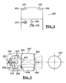
- FIG. 1 shows a view from above of the front portion 100 of a vehicle that includes dipped-beam headlamps 101, high-beam headlamps 102, and in the passenger compartment of the vehicle, a control device 103 enabling the dipped beam headlamps to be ignited; or position lights, and a video camera 104 electrically connected including a display screen 105.
- FIG. 2 is a sectional view from above of an improved traffic light 102.
- Each main beam essentially comprises a reflector 200, a light source 201, emitting light signals 210, disposed near the vertex of the reflector 200, and an output surface 202 of the light beam.
- the outlet surface 202 may be either a plastic type of ice or a suitable lens, called an exit lens, to obtain a light beam satisfying the requirements of the different standards.
- light beam is defined all the light rays that are actually emitted by a projector at the exit surface 202, the volume illuminated by the light beam corresponding to the driver's viewing zone; by light signals, denotes all the light rays emitted by the light source 201.
- the light signals 210 are emitted either directly to the output surface 202 , or indirectly after suffering any deviations and / or reflections.
- An improved high beam such as the one represented by elsewhere an infra-red filter 203, that is to say a filter passing only light signals whose wavelength belongs to the infra-red spectrum.
- the filter 203 is removable, that is to say it can move between a first position 204, said passive position, approximately horizontal in the figure, shown in dotted lines, and a second position 205, said active position, approximately vertical, represented in solid lines.
- Each filter 203 may be constituted by a rectangular or circular plate capable of pivoting about an axis of rotation 206 integral with a housing 207 in which is mounted the high beam 102.
- the pivoting of the filter 203 may for example be controlled by an electric actuator 208 which can drive a linkage system 209 to rotate the filter 203.
- the removable filter 203 is constituted by a socket associated for example with a mechanical displacement system such that the socket can surround the light source 201.
- the filter 203 In the first position, none of the light signals emitted by the light source 201 passes through the filter 203, so that visible light makes it possible to illuminate the road. In the second position, the majority of the light signals emitted by the light source 201 passes through the filter 203, so that only the infra-red signals constitute the output light beam. Some light signals 210 emitted by the light source 201 may, however, not pass through the filter 203 even when the latter is in the second position, especially in the case where there is a hole in the reflector 200 to enable the light source 201 to be fixed. In both positions, an identical light beam 211 is obtained. Such a beam projected onto a wall would give approximately a circular light spot 212.
- the light beam 211 obtained by direct lighting in visible light, or by non-visible light illumination, said indirect lighting remains the same.
- the light beam is thus made less directive.
- the rear position lamps which can be equipped with an improved projector of the type described in FIG. 2, the reflector 200 and the light source 201 being replaced by corresponding elements adapted to the rear position lamps. , and for which one may need a different light beam in direct and indirect lighting.
- EP 1 160 506 an optical module using a filter capable of filtering the visible radiation of only part of the rays emitted by the source.
- JP 2000-348513 an optical module provided with a visible ray filter as well.
- the device according to the invention proposes a solution for one or more vehicle projectors to be able to define two light beams, and thus two different viewing zones: a first vision zone corresponds to a range, a volume, directly visible to the driver by means of lighting with visible light; a second viewing area corresponds to an extent reconstructed on a control screen from an image of the considered area illuminated by means of lighting without visible light.
- the second zone of vision can be obtained when the driver wish more to use the visible light of the lights in which is installed the device according to the invention.
- it is the same light source which makes it possible to obtain two different zones of vision.
- a lens hereinafter referred to as an intermediate lens.
- This lens is disposed inside the projector so as to receive a significant portion of the light signals produced by the light source only when a non-visible light filter is in the active position, ie when the filter leaves no more passing the light signals which are produced by the light source 201 and which have a wavelength in the visible range.
- the presence of the lens causes a change in the trajectories of the light signals, and consequently changes the dispersion of the light beam.
- the dispersion of a light beam designates the direction of the light rays defining the contour, the envelope, of the light beam.
- the physical characteristics of the lens are determined according to the changes in the paths of the light beams that are desired.
- the filtering means intercepts the "light signals" emitted by the light source, the signals emitted directly by said source towards the filtering means, but also possibly the beams emitted by the source and then deflected or reflected, in particular by a reflector, before indirectly reaching the filtering means.
- the light source produces a light beam of road and / or long range type, and / or the use of the filtering means in association with the intermediate lens is implemented automatically as soon as the lights crossover are triggered.
- the projector device of FIG. 3 comprises an intermediate lens 301 detachably disposed on the path of at least a portion of the light signals 210.
- the presence of the intermediate lens allows the driver to have two light beams. 211 and 300.
- the first light beam 211 is that obtained in the state of the art in direct or indirect lighting, that is to say without or with filtering of the light signals 210 by means of the filter 203.
- the second beam 300 is preferably obtained only in indirect lighting: it is available when the intermediate lens 301 and the filtering means 203 are in an active position, that is to say in the position where on the one hand only the light signals not visible pass through the filter 203, and where on the other hand some of these signals are deflected by the intermediate lens 301.
- the intermediate lens 301 and the filtering means 203 thus intervene simultaneously on the light signals 210: in the case of the high beam 102, when the driver switches to dipped headlights 101, the filtering means 203 and the intermediate lens 301 come automatically. positioned on the path of the light signals 210 to deflect at least a portion, possibly all, and thus change the dispersion of the light beam at the output of each high beam 102.
- the driver thus obtains on his screen 105 an image, in indirect lighting, of a different extent than he could see in direct light without the intermediary of the screen.
- the intermediate lens 301 is secured to the filtering means 203, it may be, in other embodiments of the device according to the invention, disposed at other locations in within the projector.
- the various possibilities of location of the intermediate lens may in particular be intermediate positions between the light source 201 and the filtering means 203, or between the filtering means 203 and the exit surface 202.
- the fact of securing the intermediate lens 301 on one of the faces of the filtering means 203 makes it possible to avoid the addition of an additional mechanism to make the removable intermediate lens 301.
- the interlocking of the intermediate lens can be carried out on the filtering means 203 by gluing, with a glue resistant to heat, or by any other means, especially mechanical; preferably, the assembly is such that the filtering means 203 and the intermediate lens 301 are contiguous while being able to be detached from one another so that only one of these two parts can be replaced.
- the intermediate lens 301 may optionally be directly manufactured in the same material as that which constitutes the filtering means so as to form with the latter only a single piece.
- the position, the structural characteristics and the physical properties of the intermediate lens within the projector device according to the invention are chosen so that at least a portion of the light signals passing through the intermediate lens 301 are deflected to modify the dispersion of the light beam 211 present in the state of the art and thus obtain a different light beam 300.
- the light beam 300 is widened horizontally with respect to the conductor.
- such a beam projected onto a wall would give approximately an elliptical light spot 302.
- Such a modification is particularly advantageous for the driver who can obtain visual information in indirect lighting that were not accessible to him before.
- an enlargement of the light beam 300 makes it possible to reduce the intensity of the light beam at its center; the intensity being better distributed, the camera 104 used will be able to provide an image of better quality by detailing more precisely the different shades of gray visible on the screen 105.
- the device according to the invention can be designed with an infra-red filtering means 203, ie a filter that only passes light signals whose frequency belongs to the spectrum of infra-red signals, and preferably only the near infra-red frequencies that are directly adjacent to the visible frequency spectrum, or with an ultraviolet filter 203.
- violet ie a filter that only passes light signals whose frequency belongs to the spectrum of ultraviolet signals, and preferably only near ultraviolet frequencies that are directly adjacent to the frequency spectrum of the visible .
- a light source 201 of halogen type will preferably be used, whereas in the second case, a light source of the discharge lamp type, a category of which is known by the usual name of xenon lamp, will preferably be used. .
Abstract
Description
La présente invention a pour objet un dispositif projecteur bifonction pour véhicule automobile. Elle a pour but essentiel de permettre à un automobiliste de disposer, à partir d'une unique source lumineuse, d'un premier faisceau lumineux et d'un deuxième faisceau lumineux différents dans leur zone de diffusion, le premier faisceau lumineux étant essentiellement constitué de lumière visible, et le deuxième faisceau lumineux étant constitué de lumière non visible, c'est à dire d'ondes lumineuses de longueurs d'ondes situées hors du spectre visible.The present invention relates to a bifunctional projector device for a motor vehicle. Its essential purpose is to enable a motorist to have, from a single light source, a first light beam and a second light beam different in their diffusion zone, the first light beam consisting essentially of visible light, and the second light beam consisting of non-visible light, that is to say light waves of wavelengths located outside the visible spectrum.
Le domaine de l'invention est, d'une façon générale, celui des projecteurs de véhicule automobile. Dans ce domaine, on connaît différents types de projecteurs, parmi lesquels on trouve notamment :
- des feux de position, d'intensité et de portée faible ;
- des feux de croisement, ou codes, d'intensité plus forte et de portée sur la route avoisinant 70 mètres, qui sont utilisés essentiellement la nuit et dont la répartition du faisceau lumineux est telle qu'elle permet de ne pas éblouir le conducteur d'un véhicule croisé ;
- des feux de route longue portée, et des feux de complément de type longue portée ou feu anti-brouillard, dont la zone de vision sur la route avoisine 200 mètres, et qui doivent être éteints lorsque l'on croise un autre véhicule afin de ne pas éblouir son conducteur.
- position, intensity and low range lights;
- low beam, or codes, of greater intensity and range on the road of about 70 meters, which are used mainly at night and whose distribution of the light beam is such that it does not dazzle the driver of a crossover vehicle;
- long-range headlamps, and long-range typefog or fog lamps, with a vision zone on the road of approximately 200 meters, which must be extinguished when crossing another vehicle in order not to not dazzle his driver.
Par ailleurs, on connaît certains projecteurs perfectionnés, appelés projecteurs bimode, qui cumulent les fonctions de feux de croisement et de feux longue portée : à cet effet, on dispose à l'intérieur du projecteur bimode un cache, constitué par exemple d'une plaque métallique, amovible pouvant passer sur commande d'une première position dans laquelle il n'occulte pas le signal lumineux produit par la source lumineuse du projecteur, la portée du projecteur correspondant alors à celle des feux de route, à une deuxième position dans laquelle il occulte une partie du signal lumineux produit par la source lumineuse du projecteur, la portée du projecteur étant ainsi limitée à celle des feux de croisement.Furthermore, we know some advanced projectors, called two-mode projectors, which combine the functions of low beam and long range lights: for this purpose, there is inside the dual-mode projector a cover, consisting for example of a plate removable metal can be placed on command of a first position in which it does not obscure the light signal produced by the light source of the projector, the range of the projector corresponding to that of the high beam, to a second position in which it obscures a portion of the light signal produced by the light source of the projector, the range of the projector is thus limited to that of the dipped beam.
Le dispositif selon l'invention peut être mis en place dans l'un quelconque des types de projecteurs qui viennent d'être mentionnés. Sa mise en place sera plus particulièrement détaillée, à titre d'exemple uniquement, avec les feux longue portée.The device according to the invention can be implemented in any of the types of projectors which have just been mentioned. Its implementation will be more particularly detailed, as an example only with long range lights.
On connaît également dans l'état de la technique, des dispositifs d'éclairage, appelés projecteurs bifonctions, ce terme désignant un projecteur présentant de préférence au moins une fonctionnalité dans le visible et au moins une fonctionnalité hors domaine visible, qui permettent de maintenir une zone de vision étendue sans éblouir le chauffeur d'un véhicule croisé. De tels dispositifs répondent au problème selon lequel les feux longue portée doivent impérativement être éteints pour laisser place aux seuls feux de croisement lorsqu'un véhicule est croisé afin de ne pas éblouir le conducteur de ce véhicule, limitant ainsi considérablement la zone de vision au risque de ne plus éclairer suffisamment tôt d'éventuels obstacles.Also known in the state of the art, lighting devices, called bifunctional projectors, this term designating a projector preferably having at least one functionality in the visible and at least one non-visible area functionality, which allow to maintain a extended viewing area without dazzling the driver of a crossover vehicle. Such devices respond to the problem that long-range lights must be switched off to make room for only the low beam when a vehicle is crossed so as not to dazzle the driver of the vehicle, thus considerably limiting the area of vision to risk not to illuminate any obstacles early enough.
En réponse à ce problème, il a été proposé un dispositif tel que représenté à la figure 2, ce dispositif étant destiné à équiper des véhicules du type de celui illustré à la figure 1.In response to this problem, it has been proposed a device as shown in Figure 2, this device being intended to equip vehicles of the type shown in Figure 1.
La figure 1 montre une vue de dessus de la partie avant 100 d'un véhicule qui comporte des feux de croisement 101, des feux de route 102, et dans l'habitacle du véhicule, une commande 103 permettant l'allumage des feux de croisement ou des feux de position, et une caméra vidéo 104 reliée électriquement notamment à un écran de visualisation 105.FIG. 1 shows a view from above of the
La figure 2 est une vue en coupe et de dessus d'un feu de route 102 amélioré. Chaque feu de route comporte essentiellement un réflecteur 200, une source de lumière 201, émettant des signaux lumineux 210, disposée au voisinage du sommet du réflecteur 200, et une surface de sortie 202 du faisceau lumineux. La surface de sortie 202 peut être soit une glace de type plastique, soit une lentille appropriée, dite lentille de sortie, pour obtenir un faisceau lumineux satisfaisant les exigences des différentes normes. On définit par faisceau lumineux l'ensemble des rayons lumineux qui sont effectivement émis par un projecteur au niveau de la surface de sortie 202, le volume éclairé par le faisceau lumineux correspondant à la zone de vision du conducteur ; par signaux lumineux, on désigne l'ensemble des rayons lumineux émis par la source de lumière 201. Dans l'état de la technique comme dans le dispositif selon l'invention, les signaux lumineux 210 sont émis soit directement vers la surface de sortie 202, soit indirectement après avoir subi d'éventuelles déviations et/ou réflexions.Figure 2 is a sectional view from above of an improved
Un feu de route amélioré tel que celui représenté comporte par ailleurs un filtre infra-rouge 203, c'est à dire un filtre laissant passer uniquement les signaux lumineux dont la longueur d'onde appartient au spectre infra-rouge. Le filtre 203 est amovible, c'est à dire qu'il peut évoluer entre une première position 204, dite position passive, approximativement horizontale sur la figure, représentée en traits pointillés, et une deuxième position 205, dite position active, approximativement verticale, représentée en traits pleins. Chaque filtre 203 peut être constitué par une plaque de forme rectangulaire ou circulaire susceptible de pivoter autour d'un axe de rotation 206 solidaire d'un boîtier 207 dans lequel est monté le feu de route 102. Le pivotement du filtre 203 peut par exemple être commandé par un actionneur électrique 208 qui peut entraîner un système de tringlerie 209 pour faire pivoter le filtre 203. Dans d'autres modes de réalisation, on peut prévoir, par exemple, que le filtre amovible 203 est constitué par une douille associée par exemple à un système de déplacement mécanique de telle sorte que la douille puisse venir entourer la source de lumière 201.An improved high beam such as the one represented by elsewhere an infra-
Dans la première position, aucun des signaux lumineux émis par la source lumineuse 201 ne traverse le filtre 203, si bien que la lumière visible permet d'éclairer la route. Dans la deuxième position, la majorité des signaux lumineux émis par la source lumineuse 201 traverse le filtre 203, si bien que seuls les signaux infra-rouges constituent le faisceau lumineux de sortie. Certains signaux lumineux 210 émis par la source lumineuse 201 peuvent cependant ne pas traverser le filtre 203 même quand ce dernier est dans la deuxième position, notamment dans le cas où il existe un trou dans le réflecteur 200 pour permettre la fixation de la source lumineuse 201. Dans les deux positions, on obtient un faisceau lumineux identique 211. Un tel faisceau projeté sur un mur donnerait approximativement une tâche lumineuse circulaire 212.In the first position, none of the light signals emitted by the
Dans ces dispositifs de l'état de la technique, on prévoit que, lorsque le conducteur a activé ses feux de route et qu'il décide de passer au moyen de la commande 103 en feux de croisement, les feux de route ne sont pas éteints, mais le filtre 203 est mis dans sa position active. La caméra vidéo 104, sensible aux rayons infra-rouge, permet d'obtenir une image sur l'écran de contrôle 105, cette image correspondant à la zone de vision qu'il avait au moyen des feux de route. Par ailleurs, la lumière visible étant filtrée, le conducteur d'un véhicule croisé ne sera pas ébloui.In these state-of-the-art devices, it is expected that, when the driver has activated his high beam and he decides to pass by means of the
Cependant, dans les dispositifs projecteurs améliorés de l'état de la technique, le faisceau lumineux 211 obtenu par un éclairage direct en lumière visible, ou par un éclairage en lumière non visible, dit éclairage indirect, reste le même. Or dans certains cas, il peut être utile au conducteur de disposer, avec un éclairage indirect, d'un faisceau lumineux différent de celui obtenu avec un éclairage direct. Dans l'exemple décrit précédemment, il peut être intéressant d'obtenir un éclairage indirect élargi horizontalement car cela est avantageux pour le confort de conduite et l'appréciation des virages. Le faisceau lumineux est ainsi rendu moins directif. Un autre exemple est celui des feux de position arrière, qui peuvent être équipés d'un projecteur amélioré du type de celui décrit à la figure 2, le réflecteur 200 et la source lumineuse 201 étant remplacés par des éléments correspondant adaptés aux feux de position arrière, et pour lesquels on peut avoir besoin d'un faisceau lumineux différent en éclairage direct et indirect.However, in the improved projectors devices of the state of the art, the
Il est également connu de
Il est connu de
Il est connu de
Il est connu de
Il est enfin connu de
D'une façon générale, le dispositif selon l'invention propose une solution pour qu'un ou plusieurs projecteurs de véhicule puisse définir deux faisceaux lumineux, et donc deux zones de vision différentes : une première zone de vision correspond à une étendue, à un volume, directement visible par le conducteur au moyen d'un éclairage avec de la lumière visible ; une deuxième zone de vision correspond à une étendue reconstituée sur un écran de contrôle à partir d'une image de l'étendue considérée éclairée au moyen d'un éclairage sans lumière visible. La deuxième zone de vision peut être obtenue lorsque le conducteur ne souhaite plus utiliser la lumière visible des feux dans lesquels est installé le dispositif selon l'invention. Ainsi, dans l'invention, c'est la même source lumineuse qui permet d'obtenir deux zones de vision différentes.In general, the device according to the invention proposes a solution for one or more vehicle projectors to be able to define two light beams, and thus two different viewing zones: a first vision zone corresponds to a range, a volume, directly visible to the driver by means of lighting with visible light; a second viewing area corresponds to an extent reconstructed on a control screen from an image of the considered area illuminated by means of lighting without visible light. The second zone of vision can be obtained when the driver wish more to use the visible light of the lights in which is installed the device according to the invention. Thus, in the invention, it is the same light source which makes it possible to obtain two different zones of vision.
Pour atteindre cet objectif, on a prévu, dans l'invention, l'utilisation d'une lentille, désignée par la suite comme lentille intermédiaire. Cette lentille est disposée à l'intérieur du projecteur de façon à recevoir une partie significative des signaux lumineux produits par la source lumineuse uniquement lorsqu'un filtre de lumière non visible est en position active, c'est à dire lorsque ce filtre ne laisse plus passer les signaux lumineux qui sont produits par la source lumineuse 201 et qui ont une longueur d'onde dans le domaine du visible. La présence de la lentille provoque une modification des trajectoires des signaux lumineux, et change en conséquence la dispersion du faisceau lumineux. La dispersion d'un faisceau lumineux désigne la direction des rayons lumineux définissant le contour, l'enveloppe, du faisceau lumineux. Les caractéristiques physiques de la lentille sont déterminées en fonction des modifications des trajectoires des faisceaux lumineux qui sont souhaitées.To achieve this objective, it is provided in the invention, the use of a lens, hereinafter referred to as an intermediate lens. This lens is disposed inside the projector so as to receive a significant portion of the light signals produced by the light source only when a non-visible light filter is in the active position, ie when the filter leaves no more passing the light signals which are produced by the
L'invention concerne donc essentiellement un dispositif projecteur, présentant de préférence au moins une fonctionnalité dans le visible et au moins une fonctionnalité hors domaine visible, pour véhicule automobile, comportant au moins :
- une source lumineuse émettant des signaux lumineux vers une surface de sortie du projecteur pour produire un faisceau lumineux ;
- un moyen de filtrage pouvant évoluer entre une position passive dans laquelle il n'intercepte substantiellement pas les signaux lumineux émis par la dite source et une position active dans laquelle il intercepte la majorité, notamment l'essentiel, des signaux lumineux, ledit moyen de filtrage ne laissant passer qu'une partie des signaux lumineux correspondant à des longueurs d'onde non visibles ;
- a light source emitting light signals to an output surface of the projector to produce a light beam;
- filtering means capable of evolving between a passive position in which it does not substantially intercept the light signals emitted by said source and an active position in which it intercepts the majority, in particular the essential, of the light signals, said filtering means passing only a portion of the light signals corresponding to non-visible wavelengths;
On entend au sens de l'invention par le fait que le moyen de filtrage intercepte "les signaux lumineux" émis par la source lumineuse les signaux émis directement par ladite source vers le moyen de filtrage, mais aussi éventuellement les faisceaux émis par la source puis déviés ou réfléchis, notamment par un réflecteur, avant d'atteindre indirectement le moyen de filtrage.For the purposes of the invention, the filtering means intercepts the "light signals" emitted by the light source, the signals emitted directly by said source towards the filtering means, but also possibly the beams emitted by the source and then deflected or reflected, in particular by a reflector, before indirectly reaching the filtering means.
Dans un mode de réalisation particulier, la source lumineuse produit un faisceau lumineux de type route et/ou longue portée, et/ou l'utilisation du moyen de filtrage en association avec la lentille intermédiaire est mise en oeuvre de façon automatique dès que les feux de croisement du véhicule sont déclenchés.In a particular embodiment, the light source produces a light beam of road and / or long range type, and / or the use of the filtering means in association with the intermediate lens is implemented automatically as soon as the lights crossover are triggered.
Le dispositif selon l'invention peut en outre présenter une ou plusieurs des caractéristiques suivantes :
- le dispositif projecteur comprend une seconde source lumineuse apte à générer un faisceau lumineux de type feux de croisement, feux de position diurne, feux anti brouillard.
- la lentille intermédiaire est disposée de telle sorte qu'elle reçoit tout ou partie, notamment la totalité ou la quasi totalité, des signaux lumineux qui traversent le moyen de filtrage ou qui ont été filtrés par ce dernier.
- la structure et la disposition de la lentille intermédiaire permettent d'obtenir un élargissement, ou un rétrécissement, du faisceau lumineux, par exemple selon une direction horizontale.
- la lentille intermédiaire est disposée entre la source lumineuse et le moyen de filtrage.
- la lentille intermédiaire est disposée entre le moyen de filtrage et la surface de sortie.
- la lentille intermédiaire est frénélisée ou est réalisée par une pluralité de lentilles cylindriques verticales continues de type stries.
- la source lumineuse est une lampe halogène ou une lampe à décharge.
- les longueurs d'onde non visibles que le moyen de filtrage laisse passer appartiennent au moins en partie au domaine de l'infra-rouge, et de préférence du proche infra-rouge, ou de l'ultra-violet, et de préférence du proche ultra-violet.
- la lentille intermédiaire est convergente ou divergente.
- la lentille intermédiaire agit optiquement avec une deuxième lentille, dite lentille de sortie, pour obtenir un élargissement du faisceau lumineux.
- la lentille de sortie, qui peut être montée de façon fixe dans le dispositif projecteur, est disposée de façon à intercepter les signaux lumineux filtrés par le moyen de filtrage.
- le dispositif projecteur coopère avec une caméra infra-rouge et un dispositif de reproduction de l'image filmée par la caméra sur un écran d'affichage pour une vision nocturne améliorée dans un véhicule automobile.
- the projector device comprises a second light source capable of generating a light beam of the dipped beam type; daytime position, fog lights.
- the intermediate lens is arranged such that it receives all or part, in particular all or almost all, of the light signals which pass through the filtering means or which have been filtered by the latter.
- the structure and the arrangement of the intermediate lens make it possible to obtain an enlargement, or a narrowing, of the light beam, for example in a horizontal direction.
- the intermediate lens is disposed between the light source and the filtering means.
- the intermediate lens is disposed between the filter means and the exit surface.
- the intermediate lens is frenelized or is made by a plurality of continuous vertical cylindrical lenses of the streak type.
- the light source is a halogen lamp or a discharge lamp.
- the non-visible wavelengths that the filtering medium passes through belong at least in part to the infra-red domain, and preferably to the near infra-red, or to the ultraviolet, and preferably to the near-infrared region. ultraviolet.
- the intermediate lens is convergent or divergent.
- the intermediate lens optically acts with a second lens, called the exit lens, to obtain an enlargement of the light beam.
- the output lens, which can be fixedly mounted in the projector device, is arranged to intercept the light signals filtered by the filtering means.
- the projector device cooperates with an infra-red camera and a device for reproducing the image filmed by the camera on a display screen for improved night vision in a motor vehicle.
L'invention et ses différentes applications seront mieux comprises à la lecture de la description qui suit et à l'examen des figures qui l'accompagnent. Celles-ci ne sont présentées qu'à titre indicatif et nullement limitatif de l'invention. En particulier, le dispositif projecteur selon l'invention est illustré dans le cas d'une utilisation dans un feu de route, mais ce dispositif convient pour tout dispositif projecteur d'un véhicule. Les figures montrent :
- à la figure 1, déjà décrite, une représentation schématique de la face avant d'un véhicule susceptible de recevoir un dispositif projecteur selon l'invention ;
- à la figure 2, déjà décrite, un exemple de feu de route amélioré de l'état de la technique ;
- à la figure 3, un exemple de réalisation du dispositif selon l'invention dans un feu de route en vue de dessus;
- à la figure 4, une illustration de lentille frénélisée.
- in Figure 1, already described, a schematic representation of the front face of a vehicle capable of receiving a projector device according to the invention;
- in Figure 2, already described, an example of a high beam of the state of the art;
- in Figure 3, an embodiment of the device according to the invention in a high beam in top view;
- in Figure 4, a frenetic lens illustration.
A la figure 3, on retrouve l'ensemble des éléments déjà présents sur la figure 2. Les éléments communs à différentes figures ont conservé les mêmes références. Selon l'invention, le dispositif projecteur de la figure 3 comporte une lentille intermédiaire 301 disposée de façon amovible sur la trajectoire d'au moins une partie des signaux lumineux 210. La présence de la lentille intermédiaire permet au conducteur de disposer de deux faisceaux lumineux distincts 211 et 300. Le premier faisceau lumineux 211 est celui qui est obtenu dans l'état de la technique en éclairage direct ou indirect, c'est à dire sans ou avec filtrage des signaux lumineux 210 au moyen du filtre 203. Le deuxième faisceau lumineux 300 est, de préférence, obtenu seulement en éclairage indirect : il est disponible lorsque la lentille intermédiaire 301 et le moyen de filtrage 203 sont dans une position active, c'est à dire dans la position où d'une part seuls les signaux lumineux non visibles passent à travers le filtre 203, et où d'autre part une partie de ces signaux sont déviés par la lentille intermédiaire 301.In Figure 3, we find all the elements already present in Figure 2. The elements common to different figures have retained the same references. According to the invention, the projector device of FIG. 3 comprises an
La lentille intermédiaire 301 et le moyen de filtrage 203 interviennent donc simultanément sur les signaux lumineux 210 : dans le cas des feux de route 102, lorsque le conducteur passe en feux de croisement 101, le moyen de filtrage 203 et la lentille intermédiaire 301 viennent automatiquement se placer sur la trajectoire des signaux lumineux 210 pour en dévier au moins une partie, éventuellement la totalité, et modifier ainsi la dispersion du faisceau lumineux en sortie de chaque feu de route 102. Le conducteur obtient ainsi sur son écran 105 une image, en éclairage indirect, d'une étendue différente de celle qu'il pouvait voir en lumière directe sans l'intermédiaire de l'écran.The
Si sur la figure 3, donnée à titre d'exemple, la lentille intermédiaire 301 est assujettie au moyen de filtrage 203, elle peut être, dans d'autres modes de réalisation du dispositif selon l'invention, disposée à d'autres endroits au sein du projecteur. Les différentes possibilités d'emplacement de la lentille intermédiaire peuvent notamment être des positions intermédiaires entre la source de lumière 201 et le moyen de filtrage 203, ou entre le moyen de filtrage 203 et la surface de sortie 202. Le fait de solidariser la lentille intermédiaire 301 sur l'une des faces du moyen de filtrage 203 permet d'éviter l'ajout d'un mécanisme supplémentaire pour rendre la lentille intermédiaire amovible 301. La solidarisation de la lentille intermédiaire peut être effectuée sur le moyen de filtrage 203 par collage, avec une colle résistant à la chaleur, ou par tout autre moyen, notamment mécanique ; de préférence, le montage est tel que le moyen de filtrage 203 et la lentille intermédiaire 301 sont accolés tout en pouvant être désolidarisés l'un de l'autre de façon à pouvoir procéder au remplacement de seulement l'une de ces deux pièces. La lentille intermédiaire 301 peut être éventuellement directement fabriquée dans le même matériau que celui qui constitue le moyen de filtrage de façon à ne former avec ce dernier qu'une unique pièce.If in Figure 3, given by way of example, the
Afin de limiter le poids de la lentille intermédiaire 301, et ainsi de rendre moins lourd l'ensemble constitué par le moyen de filtrage et la lentille intermédiaire, il est prévu, dans le dispositif selon l'invention, la possibilité d'utiliser des lentilles frénélisées. De telles lentilles sont illustrées à la figure 4 où une lentille cylindrique est représentée dans sa structure classique 400, et sous sa forme frénélisée 401. La différence entre ces deux structures est la suppression d'un volume 402 dans la lentille frénélisée, ce volume 402 n'ayant aucune propriété optique. Dans la lentille frénélisée, on conserve l'ensemble des courbures de la lentille, elles seules présentant un réel intérêt en terme de propriétés optiques.In order to limit the weight of the
La position, les caractéristiques structurelles et les propriétés physiques de la lentille intermédiaire au sein du dispositif projecteur selon l'invention sont choisies de telle sorte qu'au moins une partie des signaux lumineux qui traversent la lentille intermédiaire 301 soient déviés pour modifier la dispersion du faisceau lumineux 211 présent dans l'état de la technique et ainsi obtenir un faisceau lumineux 300 différent. On pourra par exemple choisir des lentilles cylindriques, convergentes ou divergentes en fonction de la position qui leur est attribuée au sein du dispositif projecteur.The position, the structural characteristics and the physical properties of the intermediate lens within the projector device according to the invention are chosen so that at least a portion of the light signals passing through the
Dans le cas où la surface de sortie 202 est constituée par une lentille de sortie du dispositif projecteur, autrement dit dans le cas où la surface de sortie présente des propriétés optiques, la position de la lentille intermédiaire est adaptée pour que la combinaison des deux lentilles produise la modification du faisceau lumineux 300 attendue. On pourra notamment mettre en place les variantes suivantes de réalisation du dispositif selon l'invention, avec, en suivant le parcours des rayons lumineux dans la direction d'émission du faisceau sortant du dispositif, soit:
- la lentille intermédiaire mobile, puis le moyen de filtrage mobile, puis la lentille de sortie fixe (la lentille de sortie peut faire partie de la surface de sortie du projecteur, comme déjà mentionné, ou être montée de façon fixe "avant "cette surface de sortie, à l'intérieur du boîtier 207, de façon à être apte à intercepter les rayons filtrés par le moyen de filtrage);
- le moyen de filtrage mobile, puis la lentille intermédiaire mobile, puis la lentille de sortie fixe (elle peut aire partie de la surface de sortie ou non, comme dans la variante précédente);
- le moyen de filtrage mobile, puis la lentille de sortie fixe, puis la lentille intermédiaire mobile; dans ce dernier cas, notamment, la lentille de sortie ne correspond pas à la
surface de sortie 202, et elle est disposée à l'intérieur du boîtier 207.
- the moving intermediate lens, then the moving filtering means, and then the fixed output lens (the output lens may be part of the projector output surface, as already mentioned, or fixedly mounted "before" this surface of outlet, inside the
housing 207, so as to be able to intercept the filtered rays by the filtering means); - the mobile filtering means, then the moving intermediate lens, then the fixed output lens (it may be part of the exit surface or not, as in the previous variant);
- the moving filtering means, then the fixed output lens, and then the moving intermediate lens; in the latter case, in particular, the exit lens does not correspond to the
exit surface 202, and it is disposed inside thehousing 207.
Dans l'exemple illustré, le faisceau lumineux 300 est élargi horizontalement par rapport au conducteur. En vue de dessus, comme c'est le cas à la figure 3, un tel faisceau projeté sur un mur donnerait approximativement une tâche lumineuse elliptique 302. Une telle modification est particulièrement intéressante pour le conducteur qui peut obtenir des informations visuelles en éclairage indirect qui ne lui étaient pas accessibles auparavant. Par ailleurs, un élargissement du faisceau lumineux 300 permet de diminuer l'intensité du faisceau lumineux en son centre; l'intensité étant mieux répartie, la caméra 104 utilisée sera en mesure de fournir une image de meilleure qualité en détaillant plus précisément les différentes nuances de gris visibles sur l'écran 105.In the example shown, the
Selon différents exemples de réalisation, le dispositif selon l'invention peut être conçu avec un moyen de filtrage 203 infra-rouge, c'est à dire un filtre qui ne laisse passer que les signaux lumineux dont la fréquence appartient au spectre des signaux infra-rouge, et de préférence uniquement les fréquences du proche infra-rouge qui sont directement voisines du spectre de fréquence du visible, ou avec un filtre 203 ultra-violet, c'est à dire un filtre qui ne laisse passer que les signaux lumineux dont la fréquence appartient au spectre des signaux ultra-violet, et de préférence uniquement les fréquences du proche ultra-violet qui sont directement voisines du spectre de fréquence du visible. Dans le premier cas, on utilisera de préférence une source lumineuse 201 de type halogène, alors que dans le deuxième cas, on utilisera de préférence une source lumineuse de type lampe à décharge, dont une catégorie est connue sous la dénomination usuelle de lampe à xénon.According to various exemplary embodiments, the device according to the invention can be designed with an infra-red filtering means 203, ie a filter that only passes light signals whose frequency belongs to the spectrum of infra-red signals, and preferably only the near infra-red frequencies that are directly adjacent to the visible frequency spectrum, or with an
Claims (19)
- Headlight device, which preferably has at least one functionality in the visible domain and at least one functionality outside the visible domain, for a motor vehicle, comprising at least:- a source of light (201) which emits light signals (210) towards an output surface (202) of the headlight, in order to produce a light beam (300);- a filtering means (203) which can develop between a passive position (204) in which it substantially does not intercept the light signals (210) emitted by the said source (201) and an active position (205) in which it intercepts most, and, in particular, the essential part of the light signals (210), the said filtering means (203) permitting passage of only part of the light signals (210) corresponding to non-visible wavelengths;characterised in that in that the filtering means (203) is used in association with, or forms part of, an intermediate lens (301) in order to modify the dispersion of the light beam (300), and in that the intermediate lens (301) is integral with the filtering means (203).
- Device according to the preceding claim, characterised in that the said source of light (201) produces a light beam (300) of the full-beam and/or long-distance type.
- Device according to either of the preceding claims, characterised in that the headlight device comprises a second source of light which can generate a light beam of the dipped type, daytime position light type, or fog lamp type.
- Device according to at least one of the preceding claims, characterised in that the use of the filtering means (203) in association with the intermediate lens (301) is implemented automatically as soon as the dipped headlights (101) of the vehicle are switched on.
- Device according to one of the preceding claims, characterised in that the intermediate lens (301) is disposed such that it receives all or part of the light signals (210) which pass through the filtering means (203) or which have been filtered by the latter.
- Device according to one of the preceding claims, characterised in that the structure and the arrangement of the intermediate lens (301) make it possible to obtain widening of the light beam (300).
- Device according to the preceding claim, characterised in that the widening of the light beam (300) is carried out according to a horizontal direction.
- Device according to one of the preceding claims, characterised in that the intermediate lens (301) is disposed between the source of light (201) and the filtering means (203).
- Device according to one of claims 1 to 7, characterised in that the intermediate lens (301) is disposed between the filtering means (203) and the output surface (202).
- Device according to one of the preceding claims, characterised in that the intermediate lens (301) is stepped as a Fresnel lens or is produced by a plurality of continuous vertical cylindrical lenses of the striated type.
- Device according to one of the preceding claims, characterised in that the source of light (201) is a halogen lamp.
- Device according to one of claims 1 to 10, characterised in that the source of light (201) is a discharge lamp.
- Device according to one of the preceding claims, characterised in that the non-visible wavelengths which the filtering means (203) allows to pass belong at least partly to the infra-red domain, and preferably to the close infra-red domain.
- Device according to one of claims 1 to 12, characterised in that the non-visible wavelengths which the filtering means (203) allows to pass belong at least partly to the ultra-violet domain, and preferably to the close ultra-violet domain.
- Device according to one of the preceding claims, characterised in that the intermediate lens (301) is convergent or divergent.
- Device according to one of the preceding claims, characterised in that the intermediate lens (301) acts optically with a second lens, known as the output lens, in order to obtain widening of the light beam (300).
- Device according to the preceding claim, characterised in that the output lens is disposed such as to intercept the light signals (210) filtered by the filtering means (203).
- Device according to one of claims 16 or 17, characterised in that the output lens is fitted in a fixed manner in the headlight device.
- Device according to at least one of claims 1 to 13 and 15 to 18, characterised in that it co-operates with an infra-red camera (104) and a device for reproduction of the image filmed by the camera (104) on a display screen (105), for improved night-time vision in a motor vehicle.
Priority Applications (3)
| Application Number | Priority Date | Filing Date | Title |
|---|---|---|---|
| AT03292622T ATE383275T1 (en) | 2003-10-21 | 2003-10-21 | DUAL FUNCTION HEADLIGHT DEVICE FOR VEHICLES |
| DE60318581T DE60318581T2 (en) | 2003-10-21 | 2003-10-21 | Double-function headlamp device for motor vehicles |
| EP03292622A EP1526038B1 (en) | 2003-10-21 | 2003-10-21 | Dual-function headlamp device for vehicle |
Applications Claiming Priority (1)
| Application Number | Priority Date | Filing Date | Title |
|---|---|---|---|
| EP03292622A EP1526038B1 (en) | 2003-10-21 | 2003-10-21 | Dual-function headlamp device for vehicle |
Publications (2)
| Publication Number | Publication Date |
|---|---|
| EP1526038A1 EP1526038A1 (en) | 2005-04-27 |
| EP1526038B1 true EP1526038B1 (en) | 2008-01-09 |
Family
ID=34384706
Family Applications (1)
| Application Number | Title | Priority Date | Filing Date |
|---|---|---|---|
| EP03292622A Expired - Lifetime EP1526038B1 (en) | 2003-10-21 | 2003-10-21 | Dual-function headlamp device for vehicle |
Country Status (3)
| Country | Link |
|---|---|
| EP (1) | EP1526038B1 (en) |
| AT (1) | ATE383275T1 (en) |
| DE (1) | DE60318581T2 (en) |
Families Citing this family (2)
| Publication number | Priority date | Publication date | Assignee | Title |
|---|---|---|---|---|
| JP4714107B2 (en) * | 2006-08-09 | 2011-06-29 | 株式会社小糸製作所 | Infrared light irradiation lamp for vehicles |
| GB0815860D0 (en) * | 2008-09-01 | 2008-10-08 | Oxley Dev Co Ltd | Light emitting device |
Family Cites Families (6)
| Publication number | Priority date | Publication date | Assignee | Title |
|---|---|---|---|---|
| FR2667284B1 (en) * | 1990-10-02 | 1992-12-04 | Peugeot | PROJECTOR DEVICE FOR A MOTOR VEHICLE. |
| DE19526023A1 (en) * | 1995-07-17 | 1997-01-23 | Daimler Benz Ag | Headlamp for motor vehicle |
| JP2000348513A (en) * | 1999-05-31 | 2000-12-15 | Stanley Electric Co Ltd | Lighting fixture for car |
| JP3810976B2 (en) * | 2000-02-15 | 2006-08-16 | 株式会社小糸製作所 | Infrared irradiation lamp for automobiles |
| DE10027018B4 (en) * | 2000-05-31 | 2010-09-09 | Robert Bosch Gmbh | Vehicle headlight according to the projection principle and lighting device of a vehicle with at least one such headlight |
| FR2839138B1 (en) * | 2002-04-30 | 2005-01-07 | Valeo Vision | BIFUNCTION PROJECTOR DEVICE FOR A MOTOR VEHICLE |
-
2003
- 2003-10-21 EP EP03292622A patent/EP1526038B1/en not_active Expired - Lifetime
- 2003-10-21 DE DE60318581T patent/DE60318581T2/en not_active Expired - Lifetime
- 2003-10-21 AT AT03292622T patent/ATE383275T1/en not_active IP Right Cessation
Also Published As
| Publication number | Publication date |
|---|---|
| DE60318581D1 (en) | 2008-02-21 |
| DE60318581T2 (en) | 2008-12-24 |
| EP1526038A1 (en) | 2005-04-27 |
| ATE383275T1 (en) | 2008-01-15 |
Similar Documents
| Publication | Publication Date | Title |
|---|---|---|
| FR2839138A1 (en) | BIFUNCTION PROJECTOR DEVICE FOR A MOTOR VEHICLE | |
| EP1612474B1 (en) | Signaling and/or lighting assembly for vehicles | |
| FR2657681A1 (en) | PROJECTOR FOR AUTOMOTIVE VEHICLES, THE LIGHT SOURCE OF WHICH IS A GAS DISCHARGE LAMP. | |
| EP1308669A1 (en) | Projector-type headlamp for motor vehicles | |
| FR2922296A1 (en) | PROJECTION MODULE FOR A MOTOR VEHICLE HEADLIGHT. | |
| EP0380396B1 (en) | Motor vehicle headlamp comprising one light source and producing two different beams | |
| EP0465330B1 (en) | Headlamp with several functions, especially for vehicles | |
| FR2824623A1 (en) | VEHICLE HEADLIGHT WITH COMPOSITE LIGHT DISTRIBUTION DIAGRAM | |
| FR2946729A1 (en) | LIGHTING DEVICES, IN PARTICULAR LIGHT-EMITTING DIODES, FOR GENERATING AN ADAPTIVE LUMINOUS BEAM | |
| FR2775230A1 (en) | IMPROVED ASSEMBLY OF AT LEAST ONE PROJECTOR AND A SIGNAL LIGHT FOR A MOTOR VEHICLE | |
| FR2788836A1 (en) | MOTOR VEHICLE LIGHTING SYSTEM WITH DIURNE SIGNALING FUNCTION | |
| EP1806531A1 (en) | Multifunctional elliptical headlamp device with additional optical element | |
| FR2882589A1 (en) | Lighting/signaling device for motor vehicle, has optical unit and optical part moved between neutral and active positions to pass and intercept light rays so that device emits light and lighting/signaling beams | |
| FR3038696A1 (en) | LUMINOUS MODULE FOR LIGHTING AND / OR SIGNALING OF A MOTOR VEHICLE | |
| FR2851029A1 (en) | MOTOR VEHICLE PROJECTOR DEVICE EQUIPPED WITH LIGHT EMITTING DIODES | |
| EP1526038B1 (en) | Dual-function headlamp device for vehicle | |
| EP1944542A1 (en) | Double-function headlight for an automobile | |
| EP3124856B1 (en) | Lighting device for a motor vehicle | |
| EP1870283B1 (en) | Triple-function headlight unit for vehicle | |
| EP1260758A1 (en) | Headlight for motor vehicle | |
| FR2903946A1 (en) | Lighting system for motor vehicle, has left and right optical modules with respective light sources, which are illuminated selectively according to which vehicle is used on right or left traffic lanes | |
| FR2755413A1 (en) | VEHICLE PROJECTOR INSTALLATION | |
| FR3039879A1 (en) | BRILLIANT APPEARANCE FOR VEHICLE PROJECTOR | |
| FR2847334A1 (en) | Vehicle projector fitting, has adjustable diaphragm placed on trajectory of visible and invisible light rays to occult and partially emit visible light towards front of vehicle in respective positions of diaphragm | |
| FR2942024A1 (en) | Projection module obstructing device for headlight of vehicle i.e. motor vehicle, has deformation allowing unit allowing predetermined deformation of element so as to influence light beam emitted by projection module |
Legal Events
| Date | Code | Title | Description |
|---|---|---|---|
| PUAI | Public reference made under article 153(3) epc to a published international application that has entered the european phase |
Free format text: ORIGINAL CODE: 0009012 |
|
| AK | Designated contracting states |
Kind code of ref document: A1 Designated state(s): AT BE BG CH CY CZ DE DK EE ES FI FR GB GR HU IE IT LI LU MC NL PT RO SE SI SK TR |
|
| AX | Request for extension of the european patent |
Extension state: AL LT LV MK |
|
| 17P | Request for examination filed |
Effective date: 20050922 |
|
| AKX | Designation fees paid |
Designated state(s): AT BE BG CH CY CZ DE DK EE ES FI FR GB GR HU IE IT LI LU MC NL PT RO SE SI SK TR |
|
| GRAP | Despatch of communication of intention to grant a patent |
Free format text: ORIGINAL CODE: EPIDOSNIGR1 |
|
| RIN1 | Information on inventor provided before grant (corrected) |
Inventor name: ALBOU, PIERRE Inventor name: LELEVE, JOEL |
|
| GRAS | Grant fee paid |
Free format text: ORIGINAL CODE: EPIDOSNIGR3 |
|
| GRAA | (expected) grant |
Free format text: ORIGINAL CODE: 0009210 |
|
| AK | Designated contracting states |
Kind code of ref document: B1 Designated state(s): AT BE BG CH CY CZ DE DK EE ES FI FR GB GR HU IE IT LI LU MC NL PT RO SE SI SK TR |
|
| REG | Reference to a national code |
Ref country code: GB Ref legal event code: FG4D Free format text: NOT ENGLISH |
|
| REG | Reference to a national code |
Ref country code: CH Ref legal event code: EP |
|
| REG | Reference to a national code |
Ref country code: IE Ref legal event code: FG4D Free format text: LANGUAGE OF EP DOCUMENT: FRENCH |
|
| REF | Corresponds to: |
Ref document number: 60318581 Country of ref document: DE Date of ref document: 20080221 Kind code of ref document: P |
|
| PG25 | Lapsed in a contracting state [announced via postgrant information from national office to epo] |
Ref country code: SI Free format text: LAPSE BECAUSE OF FAILURE TO SUBMIT A TRANSLATION OF THE DESCRIPTION OR TO PAY THE FEE WITHIN THE PRESCRIBED TIME-LIMIT Effective date: 20080109 Ref country code: NL Free format text: LAPSE BECAUSE OF FAILURE TO SUBMIT A TRANSLATION OF THE DESCRIPTION OR TO PAY THE FEE WITHIN THE PRESCRIBED TIME-LIMIT Effective date: 20080109 |
|
| NLV1 | Nl: lapsed or annulled due to failure to fulfill the requirements of art. 29p and 29m of the patents act | ||
| PG25 | Lapsed in a contracting state [announced via postgrant information from national office to epo] |
Ref country code: FI Free format text: LAPSE BECAUSE OF FAILURE TO SUBMIT A TRANSLATION OF THE DESCRIPTION OR TO PAY THE FEE WITHIN THE PRESCRIBED TIME-LIMIT Effective date: 20080109 Ref country code: ES Free format text: LAPSE BECAUSE OF FAILURE TO SUBMIT A TRANSLATION OF THE DESCRIPTION OR TO PAY THE FEE WITHIN THE PRESCRIBED TIME-LIMIT Effective date: 20080420 |
|
| GBV | Gb: ep patent (uk) treated as always having been void in accordance with gb section 77(7)/1977 [no translation filed] | ||
| PG25 | Lapsed in a contracting state [announced via postgrant information from national office to epo] |
Ref country code: AT Free format text: LAPSE BECAUSE OF FAILURE TO SUBMIT A TRANSLATION OF THE DESCRIPTION OR TO PAY THE FEE WITHIN THE PRESCRIBED TIME-LIMIT Effective date: 20080109 Ref country code: BG Free format text: LAPSE BECAUSE OF FAILURE TO SUBMIT A TRANSLATION OF THE DESCRIPTION OR TO PAY THE FEE WITHIN THE PRESCRIBED TIME-LIMIT Effective date: 20080409 |
|
| PG25 | Lapsed in a contracting state [announced via postgrant information from national office to epo] |
Ref country code: PT Free format text: LAPSE BECAUSE OF FAILURE TO SUBMIT A TRANSLATION OF THE DESCRIPTION OR TO PAY THE FEE WITHIN THE PRESCRIBED TIME-LIMIT Effective date: 20080609 |
|
| REG | Reference to a national code |
Ref country code: IE Ref legal event code: FD4D |
|
| PG25 | Lapsed in a contracting state [announced via postgrant information from national office to epo] |
Ref country code: SE Free format text: LAPSE BECAUSE OF FAILURE TO SUBMIT A TRANSLATION OF THE DESCRIPTION OR TO PAY THE FEE WITHIN THE PRESCRIBED TIME-LIMIT Effective date: 20080409 Ref country code: DK Free format text: LAPSE BECAUSE OF FAILURE TO SUBMIT A TRANSLATION OF THE DESCRIPTION OR TO PAY THE FEE WITHIN THE PRESCRIBED TIME-LIMIT Effective date: 20080109 Ref country code: SK Free format text: LAPSE BECAUSE OF FAILURE TO SUBMIT A TRANSLATION OF THE DESCRIPTION OR TO PAY THE FEE WITHIN THE PRESCRIBED TIME-LIMIT Effective date: 20080109 Ref country code: CZ Free format text: LAPSE BECAUSE OF FAILURE TO SUBMIT A TRANSLATION OF THE DESCRIPTION OR TO PAY THE FEE WITHIN THE PRESCRIBED TIME-LIMIT Effective date: 20080109 Ref country code: IE Free format text: LAPSE BECAUSE OF FAILURE TO SUBMIT A TRANSLATION OF THE DESCRIPTION OR TO PAY THE FEE WITHIN THE PRESCRIBED TIME-LIMIT Effective date: 20080109 |
|
| PLBE | No opposition filed within time limit |
Free format text: ORIGINAL CODE: 0009261 |
|
| STAA | Information on the status of an ep patent application or granted ep patent |
Free format text: STATUS: NO OPPOSITION FILED WITHIN TIME LIMIT |
|
| PG25 | Lapsed in a contracting state [announced via postgrant information from national office to epo] |
Ref country code: RO Free format text: LAPSE BECAUSE OF FAILURE TO SUBMIT A TRANSLATION OF THE DESCRIPTION OR TO PAY THE FEE WITHIN THE PRESCRIBED TIME-LIMIT Effective date: 20080109 |
|
| 26N | No opposition filed |
Effective date: 20081010 |
|
| PG25 | Lapsed in a contracting state [announced via postgrant information from national office to epo] |
Ref country code: GB Free format text: LAPSE BECAUSE OF FAILURE TO SUBMIT A TRANSLATION OF THE DESCRIPTION OR TO PAY THE FEE WITHIN THE PRESCRIBED TIME-LIMIT Effective date: 20080109 |
|
| BERE | Be: lapsed |
Owner name: VALEO VISION Effective date: 20081031 |
|
| PG25 | Lapsed in a contracting state [announced via postgrant information from national office to epo] |
Ref country code: EE Free format text: LAPSE BECAUSE OF FAILURE TO SUBMIT A TRANSLATION OF THE DESCRIPTION OR TO PAY THE FEE WITHIN THE PRESCRIBED TIME-LIMIT Effective date: 20080109 |
|
| PG25 | Lapsed in a contracting state [announced via postgrant information from national office to epo] |
Ref country code: MC Free format text: LAPSE BECAUSE OF NON-PAYMENT OF DUE FEES Effective date: 20081031 |
|
| REG | Reference to a national code |
Ref country code: CH Ref legal event code: PL |
|
| PG25 | Lapsed in a contracting state [announced via postgrant information from national office to epo] |
Ref country code: CY Free format text: LAPSE BECAUSE OF FAILURE TO SUBMIT A TRANSLATION OF THE DESCRIPTION OR TO PAY THE FEE WITHIN THE PRESCRIBED TIME-LIMIT Effective date: 20080109 |
|
| PG25 | Lapsed in a contracting state [announced via postgrant information from national office to epo] |
Ref country code: IT Free format text: LAPSE BECAUSE OF FAILURE TO SUBMIT A TRANSLATION OF THE DESCRIPTION OR TO PAY THE FEE WITHIN THE PRESCRIBED TIME-LIMIT Effective date: 20080109 |
|
| PG25 | Lapsed in a contracting state [announced via postgrant information from national office to epo] |
Ref country code: BE Free format text: LAPSE BECAUSE OF NON-PAYMENT OF DUE FEES Effective date: 20081031 |
|
| PG25 | Lapsed in a contracting state [announced via postgrant information from national office to epo] |
Ref country code: CH Free format text: LAPSE BECAUSE OF NON-PAYMENT OF DUE FEES Effective date: 20081031 Ref country code: LI Free format text: LAPSE BECAUSE OF NON-PAYMENT OF DUE FEES Effective date: 20081031 |
|
| PG25 | Lapsed in a contracting state [announced via postgrant information from national office to epo] |
Ref country code: LU Free format text: LAPSE BECAUSE OF NON-PAYMENT OF DUE FEES Effective date: 20081021 Ref country code: HU Free format text: LAPSE BECAUSE OF FAILURE TO SUBMIT A TRANSLATION OF THE DESCRIPTION OR TO PAY THE FEE WITHIN THE PRESCRIBED TIME-LIMIT Effective date: 20080710 |
|
| PG25 | Lapsed in a contracting state [announced via postgrant information from national office to epo] |
Ref country code: TR Free format text: LAPSE BECAUSE OF FAILURE TO SUBMIT A TRANSLATION OF THE DESCRIPTION OR TO PAY THE FEE WITHIN THE PRESCRIBED TIME-LIMIT Effective date: 20080109 |
|
| PG25 | Lapsed in a contracting state [announced via postgrant information from national office to epo] |
Ref country code: GR Free format text: LAPSE BECAUSE OF FAILURE TO SUBMIT A TRANSLATION OF THE DESCRIPTION OR TO PAY THE FEE WITHIN THE PRESCRIBED TIME-LIMIT Effective date: 20080410 |
|
| REG | Reference to a national code |
Ref country code: FR Ref legal event code: PLFP Year of fee payment: 13 |
|
| REG | Reference to a national code |
Ref country code: FR Ref legal event code: PLFP Year of fee payment: 14 |
|
| PGFP | Annual fee paid to national office [announced via postgrant information from national office to epo] |
Ref country code: FR Payment date: 20161028 Year of fee payment: 14 Ref country code: DE Payment date: 20161013 Year of fee payment: 14 |
|
| REG | Reference to a national code |
Ref country code: DE Ref legal event code: R119 Ref document number: 60318581 Country of ref document: DE |
|
| REG | Reference to a national code |
Ref country code: FR Ref legal event code: ST Effective date: 20180629 |
|
| PG25 | Lapsed in a contracting state [announced via postgrant information from national office to epo] |
Ref country code: DE Free format text: LAPSE BECAUSE OF NON-PAYMENT OF DUE FEES Effective date: 20180501 |
|
| PG25 | Lapsed in a contracting state [announced via postgrant information from national office to epo] |
Ref country code: FR Free format text: LAPSE BECAUSE OF NON-PAYMENT OF DUE FEES Effective date: 20171031 |