EP1525928B1 - A riveting gun - Google Patents
A riveting gun Download PDFInfo
- Publication number
- EP1525928B1 EP1525928B1 EP05001636A EP05001636A EP1525928B1 EP 1525928 B1 EP1525928 B1 EP 1525928B1 EP 05001636 A EP05001636 A EP 05001636A EP 05001636 A EP05001636 A EP 05001636A EP 1525928 B1 EP1525928 B1 EP 1525928B1
- Authority
- EP
- European Patent Office
- Prior art keywords
- container
- discharge channel
- valve
- handgrip
- riveting gun
- Prior art date
- Legal status (The legal status is an assumption and is not a legal conclusion. Google has not performed a legal analysis and makes no representation as to the accuracy of the status listed.)
- Expired - Lifetime
Links
- 239000012530 fluid Substances 0.000 claims abstract description 7
- 238000003754 machining Methods 0.000 description 1
- 238000004519 manufacturing process Methods 0.000 description 1
Images

Classifications
-
- B—PERFORMING OPERATIONS; TRANSPORTING
- B21—MECHANICAL METAL-WORKING WITHOUT ESSENTIALLY REMOVING MATERIAL; PUNCHING METAL
- B21J—FORGING; HAMMERING; PRESSING METAL; RIVETING; FORGE FURNACES
- B21J15/00—Riveting
- B21J15/02—Riveting procedures
- B21J15/04—Riveting hollow rivets mechanically
- B21J15/043—Riveting hollow rivets mechanically by pulling a mandrel
-
- B—PERFORMING OPERATIONS; TRANSPORTING
- B21—MECHANICAL METAL-WORKING WITHOUT ESSENTIALLY REMOVING MATERIAL; PUNCHING METAL
- B21J—FORGING; HAMMERING; PRESSING METAL; RIVETING; FORGE FURNACES
- B21J15/00—Riveting
- B21J15/10—Riveting machines
- B21J15/105—Portable riveters
-
- B—PERFORMING OPERATIONS; TRANSPORTING
- B21—MECHANICAL METAL-WORKING WITHOUT ESSENTIALLY REMOVING MATERIAL; PUNCHING METAL
- B21J—FORGING; HAMMERING; PRESSING METAL; RIVETING; FORGE FURNACES
- B21J15/00—Riveting
- B21J15/10—Riveting machines
- B21J15/30—Particular elements, e.g. supports; Suspension equipment specially adapted for portable riveters
- B21J15/32—Devices for inserting or holding rivets in position with or without feeding arrangements
- B21J15/326—Broken-off mandrel collection
Definitions
- the aim of the present invention is to overcome the above mentioned disadvantages.
- valve 19 uninterruptedly supplies a chamber 23 inside the body 4 through a conduit, that is schematically illustrated by a continuous line, labelled 22, in Figures 1 and 2, and that extends partly inside the handgrip 2 and partly inside the body 4.
- the gripping head 6 comprises a rivet nozzle 40 screwed to the front end 41 of the casing 39 of the body 4 and two jaws 42 housed in a respective chuck 43 connected to the end of the tubular rod 34 opposite the end that is connected to the carriage 33.
Abstract
Description
- The present invention relates to a riveting gun.
- Prior art riveting guns of this type, designed to apply break mandrel rivets of any kind, comprise a handgrip or handle and a substantially cylindrical body attached to the handgrip transversally to the latter and equipped at one end with a rivet gripping and breaking off head.
- The handgrip houses a pneumatic cylinder and piston assembly which drives the piston of a hydraulic cylinder housed in the body and coaxial with the latter.
- The piston of the hydraulic cylinder has attached to it a tubular rod, coaxial with the body, one end of which is associated with the rivet gripping head, as shown in
document GB 2 116 102. - The rivets are applied as follows.
- The rivet, held by the riveting gun gripping head, is positioned inside the hole made in the parts to be joined. The user then pulls the trigger on the handgrip. This opens a first shutoff valve which puts a compressed air source into communication with a chamber of the pneumatic cylinder, which causes the related piston to perform its forward stroke.
- This piston is equipped with a rod which, during the forward stroke, runs through an oil filled chamber inside the handgrip and communicating with the thrust chamber of the piston of the hydraulic cylinder.
- As it moves away from the rivet gripping head against the opposing action of a return spring, the piston applies, through the cylinder rod and gripping head, a pulling force that upsets a portion of the rivet on the parts to be joined and at the same time breaks off the rivet mandrel or stem.
- It has been found, however, that the hydraulic mechanism that drives riveting guns of this type has the inevitable disadvantage connected with oil leaks. Leaking obviously gets worse as the gun gets older.
- This means that the oil must be renewed or at least topped up at regular intervals.
- The attempts to overcome this disadvantage by more precise machining of the critical parts responsible for leakages and by adding oil seals have considerably increased production costs without fully solving the problem.
- Also known to prior art are riveting guns fitted with containers for collecting riveting debris, this debris, as is well known, consisting of the spent rivet mandrels or stems.
- More specifically, the mandrel of each rivet, after being broken off, is ejected through a discharge channel coaxial with the riveting gun head and extending between an inlet at the gripping head and outlet leading into the container, which is fixed to the body on the side opposite the gripping head.
- The mandrel is driven along the discharge channel by a stream of compressed air.
- If the container is removed from the gun body, to empty it when it is full, for example, a safety device prevents mandrels from being ejected until the container is put back in place again.
- The safety device may consist of a hand-operated valve to shut off the compressed air system or even mechanical gate valve means to close the discharge channel.
- Neither of these types of device, however, provide a sufficient guarantee of safety.
- Indeed, the former rely on a manual operation and the latter, on account of the high pressure in the pneumatic system and since they do not interrupt the circulation of air in the system, may cause the mandrel to backfire through the inlet of the discharge channel.
- The aim of the present invention is to overcome the above mentioned disadvantages.
- Accordingly, the present invention provides a riveting gun in accordance with
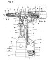
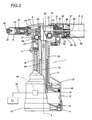
claim 1. The invention will now be described with reference to the accompanying drawings which illustrate preferred embodiments of it and in which: - Figures 1 and 2 are longitudinal sections of a riveting gun according to the present invention in two working positions;
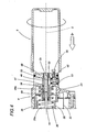
- Figures 3 and 4 show a part of the riveting gun of Figure 1 in two different operating conditions.
- With reference to Figures 1 and 2, the
numeral 1 denotes in its entirety a riveting gun, in particular a pneumatic one, comprising anelongated handgrip 2 whose longitudinal axis is labelled 3. - One end of the
handgrip 2 is attached to a substantially cylindrical body 4, whose longitudinal axis, labelled 5, is substantially transversal to theaxis 3 of thehandgrip 2. - A first end of the body 4 is equipped with a
head 6 for gripping themandrels 7 of therivets 8, and the second end is equipped with acylindrical container 9 coaxial with the body 4 and designed to collect thespent mandrels 7 discharged from the rivetinggun 1 after upsetting of therivets 8. - The free end of the
handgrip 2, labelled 10 in its entirety, is substantially cylindrical in shape, is closed by abottom wall 11 and defines within it acylindrical cavity 12, which is divided by apiston 13 into afirst chamber 14, between thepiston 13 and thebottom wall 11, and asecond chamber 15 between thepiston 13 and an end wall, labelled 16, that is substantially parallel to thebottom wall 11. - More specifically, the
cylindrical cavity 12 and thepiston 13 together constitute first actuating means associated with thehandgrip 2. - At the end of the
handgrip 2 close to the casing 4, there is pivotally mounted atrigger 17. The latter, acting, in conjunction with arod 18 parallel to theaxis 3 and sliding in a direction parallel to theaxis 3, actuates a distribution valve illustrated schematically as ablock 19. Thevalve 19 is connected through apipe 20 to acompressed air source 21. - When the
trigger 17 is pulled, thevalve 19 connects thesource 21 in known manner directly with thefirst chamber 14 so as to drive thepiston 13 from the rest position illustrated in Figure 1 to the working position illustrated in Figure 2. Alternatively, thevalve 19 can also connect thesource 21 in known manner directly with thesecond chamber 15 so as to drive thepiston 13 from the working position illustrated in Figure 2 to the rest position illustrated in Figure 1. - Also in known manner and for the reasons described below, the
valve 19 uninterruptedly supplies achamber 23 inside the body 4 through a conduit, that is schematically illustrated by a continuous line, labelled 22, in Figures 1 and 2, and that extends partly inside thehandgrip 2 and partly inside the body 4. - As shown in Figures 1 and 2, the
piston 13 is attached to arod 24 that is coaxial with theaxis 3 of thehandgrip 2 and slides in aguide sleeve 25 made in thehandgrip 2 itself. Fitted on the end of therod 24 facing the body 4 there is awedge 26, oneface 27 of which is parallel to theaxis 3 and anotherface 28, opposite theface 27, being at a defined angle to theaxis 3 and constituting the active pushing section of acam element 29 comprising a camfollower push roller 30 and a contact andguide roller 31. Specifically, thecam follower 30, which cooperates with theangled face 28 of thewedge 26, is rotatably mounted on ashaft 32, whose axis is transversal to theaxis 5 and which is in turn mounted on acarriage 33 housed in the body 4 and running in the direction of theaxis 5. More specifically, thewedge 26, theroller 30 and thecarriage 33 together constitute second actuating means connected to the first actuating means by therod 24. - As shown in Figures 1 and 2, the
carriage 33 is connected by atubular rod 34 to thegripping head 6, whilst on the side of thecarriage 33 opposite thegripping head 6, there is a cup-like element 35 that defines aseat 35a accommodating an end portion of an opposinghelical spring 36 fitted between theend wall 37 of theseat 35a and awall 38 transversal to theaxis 5, parallel to theend wall 37 and attached to theouter casing 39 defining the body 4. - Looking in more detail, with reference also to Figures 3 and 4, the
seat 35a defined by the aforementioned cup-like element 35 and theface 38 form thechamber 23 into which theconduit 22 leads. - The gripping
head 6 comprises arivet nozzle 40 screwed to thefront end 41 of thecasing 39 of the body 4 and twojaws 42 housed in arespective chuck 43 connected to the end of thetubular rod 34 opposite the end that is connected to thecarriage 33. - With reference to Figures 1 and 2, the
numeral 44 denotes a discharge channel for themandrels 7 of therivets 8. This channel is coaxial with theaxis 5 and presents an inlet at thenozzle 40 and an outlet leading into thecontainer 9 and extending further through thegripping head 6, thetubular rod 34, thecarriage 33 and thewalls - As shown in more detail in Figures 2 and 3, the
chamber 23 is connected, through ahole 45 made in thewall 38, to anannular chamber 46 extending around asleeve 47 that is coaxial with theaxis 5 connecting thewall 38 with anend wall 48 of thecasing 39 of the body 4. With its outer cylindrical surface, theend wall 48 constitutes a connector element for an open end 9a of thecontainer 9. - The aforementioned
annular chamber 46 is connected, through apassage 46a, to ahole 49 that crosses thesleeve 47 at an angle towards the outlet of thedischarge channel 44, in such a way that the fluid supplied by thesource 21 flowing through theconduit 22 produces a Venturi effect that generates a vacuum inside thedischarge channel 44 capable of creating a sucking action directed towards the outlet of thedischarge channel 44. - The invention will now be described with reference to the operation of the riveting gun starting from the conditions illustrated in Figure 1, where a
rivet 8, associated with the parts to be joined (not illustrated), has been inserted with itsmandrel 7 into thenozzle 40 of thegripping head 6. When thetrigger 17 is pulled, thevalve 19, actuated by therod 18, enables fluid under pressure supplied by thesource 21 to flow into thefirst chamber 14 and to drive thepiston 13 along thecylindrical cavity 12 from the position illustrated in Figure 1 towards the working position illustrated in Figure 2. - As a result of this, the
rod 24 slides inside thesleeve 25 and enables thewedge 26 to move thecarriage 33 in the direction of theaxis 5 towards thecontainer 9, as indicated by the arrow F1. More specifically, theface 27 parallel to theaxis 3 runs on the contact andguide roller 31, while theangled face 28 of thewedge 26 cooperates and interacts with the camfollower push roller 30 in such a way as to drive thecarriage 33 and hence thetubular rod 34, thegripping head 6 and thechuck 43 along the body 4. As a result of this movement and against the opposing action of thespring 36, thejaws 42 tighten around themandrel 7, pulling it and breaking it off while at the same time upsetting therivet 8 on the parts to be joined. - At this point, the vacuum generated by the Venturi effect inside the
discharge channel 44 produces suction which draws thebroken mandrel 7 into thecontainer 9 through thedischarge channel 44. - When the
trigger 17 is released, thevalve 19 stops the compressed air from flowing into thefirst chamber 14 and causes it to flow into thesecond chamber 15 so as to drive thepiston 13 back to the rest position of Figure 1 so that thecam element 29 moves to the lowered position, causing thecarriage 33 to move in the direction opposite that indicated by the arrow F1 under the action of thespring 36. This cycle is repeated for eachrivet 8. - As shown in more detail in Figures 3 and 4, the
hole 45 reaches theannular chamber 46 through shutoff means 50 consisting of avalve 51 that opens and closes aconduit 52 which pneumatically connects thehole 45 to theannular chamber 46. - More specifically, the
chamber 23, thehole 45, theconduit 52, theannular chamber 46, thepassage 46a and theangled hole 49 together constitute a circuit that pneumatically connects theconduit 22 to thedischarge chamber 44. - The
valve 51 is located inside aradial seat 53 formed in theouter housing 39 with one end open to the outside environment and can move between two stable positions. In the first of these positions, illustrated in Figure 4, theconduit 52 is closed, when thecontainer 9 is removed, under the thrusting action of the air present inside the pneumatic circuit acting between thehead 55 of thevalve 51 and the end wall of theannular chamber 46. In this position, thevalve 51 is held inside itsseat 53 by astop screw 56. - The
valve 51 moves to the second stable position, illustrated in Figure 3, in which theconduit 52 is open, when thecontainer 9 is applied to the back of theend wall 48 of thecasing 39 of the body 4. - Specifically, the
container 9 is applied to theend wall 48 by an axial movement such that the open end 9a of thecontainer 9 fits over the outer surface of theend wall 48. Next, by a screwing action about theaxis 5, thecontainer 9, thanks to two helical sectors 57 made on the inside surface of its open end 9a, intercepts a cap 58 on the outside of thevalve 51, causing the latter to gradually move radially in the direction of theaxis 5 itself and overcoming the resistance of the compressed air and thus re-opening the connectingconduit 52. - From the above description, it is clear that when the
container 9 is not fitted, thevalve 51 is always in the position in which it closes thepneumatic conduit 52, thus closing the aforementioned pneumatic circuit and interrupting the flow of air through thedischarge channel 44 so as to avoid any risk ofrivet 8mandrels 7 being accidentally ejected from the outlet of thechannel 44 itself.
Claims (2)
- A riveting gun comprising a handgrip (2), extending along a longitudinal axis (3), and a substantially cylindrical body (4) attached to the handgrip (2) transversally to the latter along an axis (5) and equipped at one end (41) with a head (6) for gripping the rivet (8) mandrels (7), and further comprising a container (9) that can be fixed to the body (4) at the end opposite the gripping head (6), first actuating means (12, 13) associated with the handgrip (2), second actuating means (26, 30, 33) associated with the body (4) and controlled by the first actuating means (12, 13), designed to apply to the gripping head (6) a pulling force in the direction (F1) of the axis (5) of said cylindrical body (4), a discharge channel (44) coaxial with the body (4) and extending between an inlet at the gripping head (6) and an outlet leading into the container (9) pneumatic means (19, 20, 21, 22) connected to the discharge channel (44) by a pneumatic circuit (23, 45, 46, 46a, 49, 52) and designed to produce a stream of fluid that discharges rivet (8) mandrels (7) into the container (9), the riveting gun being characterised in that the pneumatic means (19, 20, 21, 22) comprise shutoff means (50) for interrupting the stream of fluid; the shutoff means consisting of a valve (51) that closes and opens the circuit; the valve (51) being mounted in a radial seat (53) formed in the body (4) with one end open to the outside environment; the valve (51) being able to move in a radial direction between two stable positions, in the first of which the pneumatic circuit (23, 45, 46, 46a, 49, 52) is closed, when the container (9) is removed, and in the second of which the pneumatic circuit (23, 45, 46, 46a, 49, 52) is opened when the container (9) is fitted to the body (4).
- The riveting gun according to claim 1, characterised in that it comprises also an annular chamber (46) connected, through a passage (46a), to a hole (49) that crosses a sleeve (47) at an angle towards the outlet of the discharge channel (44), in such a way that the fluid supplied by a compressed air source (21) flowing through a conduit (22) produces a Venturi effect that generates a vacuum inside the discharge channel (44) capable of creating a sucking action directed towards the outlet of the discharge channel (44).
Applications Claiming Priority (3)
| Application Number | Priority Date | Filing Date | Title |
|---|---|---|---|
| IT2001BO000591A ITBO20010591A1 (en) | 2001-09-26 | 2001-09-26 | RIVETING PISTOL |
| ITBO20010591 | 2001-09-26 | ||
| EP02425567A EP1300205B1 (en) | 2001-09-26 | 2002-09-20 | A riveting gun |
Related Parent Applications (1)
| Application Number | Title | Priority Date | Filing Date |
|---|---|---|---|
| EP02425567A Division EP1300205B1 (en) | 2001-09-26 | 2002-09-20 | A riveting gun |
Publications (3)
| Publication Number | Publication Date |
|---|---|
| EP1525928A2 EP1525928A2 (en) | 2005-04-27 |
| EP1525928A3 EP1525928A3 (en) | 2005-05-04 |
| EP1525928B1 true EP1525928B1 (en) | 2007-05-02 |
Family
ID=11439636
Family Applications (2)
| Application Number | Title | Priority Date | Filing Date |
|---|---|---|---|
| EP05001636A Expired - Lifetime EP1525928B1 (en) | 2001-09-26 | 2002-09-20 | A riveting gun |
| EP02425567A Expired - Lifetime EP1300205B1 (en) | 2001-09-26 | 2002-09-20 | A riveting gun |
Family Applications After (1)
| Application Number | Title | Priority Date | Filing Date |
|---|---|---|---|
| EP02425567A Expired - Lifetime EP1300205B1 (en) | 2001-09-26 | 2002-09-20 | A riveting gun |
Country Status (5)
| Country | Link |
|---|---|
| EP (2) | EP1525928B1 (en) |
| AT (2) | ATE361165T1 (en) |
| DE (2) | DE60203576T2 (en) |
| ES (1) | ES2286721T3 (en) |
| IT (1) | ITBO20010591A1 (en) |
Cited By (1)
| Publication number | Priority date | Publication date | Assignee | Title |
|---|---|---|---|---|
| WO2024002429A1 (en) * | 2022-06-30 | 2024-01-04 | SFS Group Germany GmbH | Riveting device, collecting container for remaining riveting mandrels, and method for installing and uninstalling such a collecting container |
Families Citing this family (8)
| Publication number | Priority date | Publication date | Assignee | Title |
|---|---|---|---|---|
| GB2455730B (en) | 2007-12-19 | 2009-12-23 | Avdel Uk Ltd | Fastener Installation Tool |
| CN101224485B (en) * | 2008-01-25 | 2010-10-06 | 孙延新 | Easy squeeze blind rivet gun |
| CN101224486B (en) * | 2008-01-25 | 2010-10-06 | 孙延新 | Rivet pulling device of easy squeeze blind rivet gun |
| DE102010024610B4 (en) * | 2010-06-22 | 2012-02-16 | Gesipa Blindniettechnik Gmbh | Setting tool with a variable setting stroke adjustment |
| CN201862729U (en) * | 2010-11-30 | 2011-06-15 | 洪良明 | Machine core of electrical core pulling riveting gun |
| JP5707267B2 (en) * | 2011-07-22 | 2015-04-22 | 株式会社マキタ | Electric tool |
| US10022782B1 (en) | 2017-01-13 | 2018-07-17 | Milawukee Electric Tool Corporation | Attachment for a rivet setting tool |
| CN219632508U (en) | 2020-06-03 | 2023-09-05 | 米沃奇电动工具公司 | Rivet tool and power tool for setting rivets |
Family Cites Families (3)
| Publication number | Priority date | Publication date | Assignee | Title |
|---|---|---|---|---|
| US2396001A (en) * | 1944-05-30 | 1946-03-05 | Chicago Pneumatic Tool Co | Pull gun |
| GB2116102A (en) * | 1982-03-08 | 1983-09-21 | Avdel Ltd | Riveting tool |
| US5086551A (en) * | 1990-09-05 | 1992-02-11 | Emhart Inc. | Rivet setting tool |
-
2001
- 2001-09-26 IT IT2001BO000591A patent/ITBO20010591A1/en unknown
-
2002
- 2002-09-20 AT AT05001636T patent/ATE361165T1/en not_active IP Right Cessation
- 2002-09-20 ES ES05001636T patent/ES2286721T3/en not_active Expired - Lifetime
- 2002-09-20 EP EP05001636A patent/EP1525928B1/en not_active Expired - Lifetime
- 2002-09-20 DE DE60203576T patent/DE60203576T2/en not_active Expired - Lifetime
- 2002-09-20 AT AT02425567T patent/ATE292533T1/en not_active IP Right Cessation
- 2002-09-20 EP EP02425567A patent/EP1300205B1/en not_active Expired - Lifetime
- 2002-09-20 DE DE60219967T patent/DE60219967T2/en not_active Expired - Lifetime
Cited By (1)
| Publication number | Priority date | Publication date | Assignee | Title |
|---|---|---|---|---|
| WO2024002429A1 (en) * | 2022-06-30 | 2024-01-04 | SFS Group Germany GmbH | Riveting device, collecting container for remaining riveting mandrels, and method for installing and uninstalling such a collecting container |
Also Published As
| Publication number | Publication date |
|---|---|
| EP1300205A2 (en) | 2003-04-09 |
| EP1525928A2 (en) | 2005-04-27 |
| DE60203576T2 (en) | 2006-02-09 |
| DE60219967T2 (en) | 2008-01-17 |
| EP1525928A3 (en) | 2005-05-04 |
| ES2286721T3 (en) | 2007-12-01 |
| ATE361165T1 (en) | 2007-05-15 |
| ITBO20010591A1 (en) | 2003-03-26 |
| DE60203576D1 (en) | 2005-05-12 |
| EP1300205B1 (en) | 2005-04-06 |
| ITBO20010591A0 (en) | 2001-09-26 |
| DE60219967D1 (en) | 2007-06-14 |
| ATE292533T1 (en) | 2005-04-15 |
| EP1300205A3 (en) | 2003-08-06 |
Similar Documents
| Publication | Publication Date | Title |
|---|---|---|
| EP1525928B1 (en) | A riveting gun | |
| US4132243A (en) | Apparatus for feeding perforation sealer balls and the like into well treating fluid | |
| US5697136A (en) | Fastener installation tool | |
| US4628722A (en) | Setting tool for rivet with pull-headed mandrel | |
| US4250972A (en) | Pneumatic ram boring device | |
| EP0484839A2 (en) | Reversible impact-operated boring tool | |
| TWI247651B (en) | Nail gun provided with duster function | |
| US4866972A (en) | Rivet setting tool for setting blind rivets | |
| EP0201292A2 (en) | Breakstem fastener installation tool | |
| JP2709169B2 (en) | Control valve for mandrel collector | |
| US5533579A (en) | Shock preventive pneumatic tool as automatically shut off under no load condition | |
| GB2116102A (en) | Riveting tool | |
| US5086551A (en) | Rivet setting tool | |
| EP2029325B1 (en) | Delayed compression sleeve hammer | |
| EP1901883B1 (en) | Pneumatic assembly for an installation that is used for the blast cleaning of foundry cores | |
| EP1402974A2 (en) | A rivet gun for threaded rivets | |
| EP3895811B1 (en) | Hot melt glue gun having needle valve | |
| US2445524A (en) | Automatic shut-off valve for hose nozzles | |
| GB2171947A (en) | Blind riveting tool | |
| CN109028670B (en) | Refrigerant filling gun | |
| JP2004353682A (en) | Opening/closing valve | |
| US5167058A (en) | Continuous reciprocating tube-stripping apparatus | |
| EP1901882B1 (en) | Pneumatic assembly for an installation that is used for the blast cleaning of foundry cores | |
| EP1901869B1 (en) | Pneumatic assembly for an installation that is used for the blast cleaning of foundry cores | |
| JP2994554B2 (en) | Housing structure for hydraulically operated fastening tools |
Legal Events
| Date | Code | Title | Description |
|---|---|---|---|
| PUAI | Public reference made under article 153(3) epc to a published international application that has entered the european phase |
Free format text: ORIGINAL CODE: 0009012 |
|
| PUAL | Search report despatched |
Free format text: ORIGINAL CODE: 0009013 |
|
| AC | Divisional application: reference to earlier application |
Ref document number: 1300205 Country of ref document: EP Kind code of ref document: P |
|
| AK | Designated contracting states |
Kind code of ref document: A2 Designated state(s): AT BE BG CH CY CZ DE DK EE ES FI FR GB GR IE IT LI LU MC NL PT SE SK TR |
|
| AK | Designated contracting states |
Kind code of ref document: A3 Designated state(s): AT BE BG CH CY CZ DE DK EE ES FI FR GB GR IE IT LI LU MC NL PT SE SK TR |
|
| 17P | Request for examination filed |
Effective date: 20050721 |
|
| AKX | Designation fees paid |
Designated state(s): AT BE BG CH CY CZ DE DK EE ES FI FR GB GR IE IT LI LU MC NL PT SE SK TR |
|
| GRAP | Despatch of communication of intention to grant a patent |
Free format text: ORIGINAL CODE: EPIDOSNIGR1 |
|
| GRAS | Grant fee paid |
Free format text: ORIGINAL CODE: EPIDOSNIGR3 |
|
| GRAA | (expected) grant |
Free format text: ORIGINAL CODE: 0009210 |
|
| AC | Divisional application: reference to earlier application |
Ref document number: 1300205 Country of ref document: EP Kind code of ref document: P |
|
| AK | Designated contracting states |
Kind code of ref document: B1 Designated state(s): AT BE BG CH CY CZ DE DK EE ES FI FR GB GR IE IT LI LU MC NL PT SE SK TR |
|
| PG25 | Lapsed in a contracting state [announced via postgrant information from national office to epo] |
Ref country code: CH Free format text: LAPSE BECAUSE OF FAILURE TO SUBMIT A TRANSLATION OF THE DESCRIPTION OR TO PAY THE FEE WITHIN THE PRESCRIBED TIME-LIMIT Effective date: 20070502 Ref country code: FI Free format text: LAPSE BECAUSE OF FAILURE TO SUBMIT A TRANSLATION OF THE DESCRIPTION OR TO PAY THE FEE WITHIN THE PRESCRIBED TIME-LIMIT Effective date: 20070502 Ref country code: LI Free format text: LAPSE BECAUSE OF FAILURE TO SUBMIT A TRANSLATION OF THE DESCRIPTION OR TO PAY THE FEE WITHIN THE PRESCRIBED TIME-LIMIT Effective date: 20070502 |
|
| RAP1 | Party data changed (applicant data changed or rights of an application transferred) |
Owner name: FAR S.R.L. |
|
| REG | Reference to a national code |
Ref country code: GB Ref legal event code: FG4D |
|
| REG | Reference to a national code |
Ref country code: CH Ref legal event code: EP |
|
| REG | Reference to a national code |
Ref country code: IE Ref legal event code: FG4D |
|
| REF | Corresponds to: |
Ref document number: 60219967 Country of ref document: DE Date of ref document: 20070614 Kind code of ref document: P |
|
| PG25 | Lapsed in a contracting state [announced via postgrant information from national office to epo] |
Ref country code: SE Free format text: LAPSE BECAUSE OF FAILURE TO SUBMIT A TRANSLATION OF THE DESCRIPTION OR TO PAY THE FEE WITHIN THE PRESCRIBED TIME-LIMIT Effective date: 20070802 |
|
| ET | Fr: translation filed | ||
| NLV1 | Nl: lapsed or annulled due to failure to fulfill the requirements of art. 29p and 29m of the patents act | ||
| REG | Reference to a national code |
Ref country code: CH Ref legal event code: PL |
|
| PG25 | Lapsed in a contracting state [announced via postgrant information from national office to epo] |
Ref country code: AT Free format text: LAPSE BECAUSE OF FAILURE TO SUBMIT A TRANSLATION OF THE DESCRIPTION OR TO PAY THE FEE WITHIN THE PRESCRIBED TIME-LIMIT Effective date: 20070502 |
|
| REG | Reference to a national code |
Ref country code: ES Ref legal event code: FG2A Ref document number: 2286721 Country of ref document: ES Kind code of ref document: T3 |
|
| PG25 | Lapsed in a contracting state [announced via postgrant information from national office to epo] |
Ref country code: BE Free format text: LAPSE BECAUSE OF FAILURE TO SUBMIT A TRANSLATION OF THE DESCRIPTION OR TO PAY THE FEE WITHIN THE PRESCRIBED TIME-LIMIT Effective date: 20070502 |
|
| PG25 | Lapsed in a contracting state [announced via postgrant information from national office to epo] |
Ref country code: DK Free format text: LAPSE BECAUSE OF FAILURE TO SUBMIT A TRANSLATION OF THE DESCRIPTION OR TO PAY THE FEE WITHIN THE PRESCRIBED TIME-LIMIT Effective date: 20070502 Ref country code: CZ Free format text: LAPSE BECAUSE OF FAILURE TO SUBMIT A TRANSLATION OF THE DESCRIPTION OR TO PAY THE FEE WITHIN THE PRESCRIBED TIME-LIMIT Effective date: 20070502 Ref country code: NL Free format text: LAPSE BECAUSE OF FAILURE TO SUBMIT A TRANSLATION OF THE DESCRIPTION OR TO PAY THE FEE WITHIN THE PRESCRIBED TIME-LIMIT Effective date: 20070502 Ref country code: PT Free format text: LAPSE BECAUSE OF FAILURE TO SUBMIT A TRANSLATION OF THE DESCRIPTION OR TO PAY THE FEE WITHIN THE PRESCRIBED TIME-LIMIT Effective date: 20071002 Ref country code: BG Free format text: LAPSE BECAUSE OF FAILURE TO SUBMIT A TRANSLATION OF THE DESCRIPTION OR TO PAY THE FEE WITHIN THE PRESCRIBED TIME-LIMIT Effective date: 20070802 |
|
| PG25 | Lapsed in a contracting state [announced via postgrant information from national office to epo] |
Ref country code: SK Free format text: LAPSE BECAUSE OF FAILURE TO SUBMIT A TRANSLATION OF THE DESCRIPTION OR TO PAY THE FEE WITHIN THE PRESCRIBED TIME-LIMIT Effective date: 20070502 |
|
| PLBE | No opposition filed within time limit |
Free format text: ORIGINAL CODE: 0009261 |
|
| STAA | Information on the status of an ep patent application or granted ep patent |
Free format text: STATUS: NO OPPOSITION FILED WITHIN TIME LIMIT |
|
| 26N | No opposition filed |
Effective date: 20080205 |
|
| PG25 | Lapsed in a contracting state [announced via postgrant information from national office to epo] |
Ref country code: MC Free format text: LAPSE BECAUSE OF NON-PAYMENT OF DUE FEES Effective date: 20070930 Ref country code: GR Free format text: LAPSE BECAUSE OF FAILURE TO SUBMIT A TRANSLATION OF THE DESCRIPTION OR TO PAY THE FEE WITHIN THE PRESCRIBED TIME-LIMIT Effective date: 20070803 |
|
| GBPC | Gb: european patent ceased through non-payment of renewal fee |
Effective date: 20070920 |
|
| PG25 | Lapsed in a contracting state [announced via postgrant information from national office to epo] |
Ref country code: IE Free format text: LAPSE BECAUSE OF NON-PAYMENT OF DUE FEES Effective date: 20070920 |
|
| PG25 | Lapsed in a contracting state [announced via postgrant information from national office to epo] |
Ref country code: GB Free format text: LAPSE BECAUSE OF NON-PAYMENT OF DUE FEES Effective date: 20070920 |
|
| PG25 | Lapsed in a contracting state [announced via postgrant information from national office to epo] |
Ref country code: EE Free format text: LAPSE BECAUSE OF FAILURE TO SUBMIT A TRANSLATION OF THE DESCRIPTION OR TO PAY THE FEE WITHIN THE PRESCRIBED TIME-LIMIT Effective date: 20070502 |
|
| PG25 | Lapsed in a contracting state [announced via postgrant information from national office to epo] |
Ref country code: CY Free format text: LAPSE BECAUSE OF FAILURE TO SUBMIT A TRANSLATION OF THE DESCRIPTION OR TO PAY THE FEE WITHIN THE PRESCRIBED TIME-LIMIT Effective date: 20070502 |
|
| PG25 | Lapsed in a contracting state [announced via postgrant information from national office to epo] |
Ref country code: LU Free format text: LAPSE BECAUSE OF NON-PAYMENT OF DUE FEES Effective date: 20070920 |
|
| PG25 | Lapsed in a contracting state [announced via postgrant information from national office to epo] |
Ref country code: TR Free format text: LAPSE BECAUSE OF FAILURE TO SUBMIT A TRANSLATION OF THE DESCRIPTION OR TO PAY THE FEE WITHIN THE PRESCRIBED TIME-LIMIT Effective date: 20070502 |
|
| PGFP | Annual fee paid to national office [announced via postgrant information from national office to epo] |
Ref country code: IT Payment date: 20130925 Year of fee payment: 12 |
|
| PGFP | Annual fee paid to national office [announced via postgrant information from national office to epo] |
Ref country code: DE Payment date: 20131129 Year of fee payment: 12 Ref country code: FR Payment date: 20130927 Year of fee payment: 12 |
|
| PGFP | Annual fee paid to national office [announced via postgrant information from national office to epo] |
Ref country code: ES Payment date: 20131025 Year of fee payment: 12 |
|
| REG | Reference to a national code |
Ref country code: DE Ref legal event code: R119 Ref document number: 60219967 Country of ref document: DE |
|
| REG | Reference to a national code |
Ref country code: FR Ref legal event code: ST Effective date: 20150529 |
|
| PG25 | Lapsed in a contracting state [announced via postgrant information from national office to epo] |
Ref country code: DE Free format text: LAPSE BECAUSE OF NON-PAYMENT OF DUE FEES Effective date: 20150401 |
|
| PG25 | Lapsed in a contracting state [announced via postgrant information from national office to epo] |
Ref country code: FR Free format text: LAPSE BECAUSE OF NON-PAYMENT OF DUE FEES Effective date: 20140930 Ref country code: IT Free format text: LAPSE BECAUSE OF NON-PAYMENT OF DUE FEES Effective date: 20140920 |
|
| REG | Reference to a national code |
Ref country code: ES Ref legal event code: FD2A Effective date: 20160602 |
|
| PG25 | Lapsed in a contracting state [announced via postgrant information from national office to epo] |
Ref country code: ES Free format text: LAPSE BECAUSE OF NON-PAYMENT OF DUE FEES Effective date: 20140921 |