EP1525822A1 - Improvements introduced in multi-purpose lockers - Google Patents
Improvements introduced in multi-purpose lockers Download PDFInfo
- Publication number
- EP1525822A1 EP1525822A1 EP04024804A EP04024804A EP1525822A1 EP 1525822 A1 EP1525822 A1 EP 1525822A1 EP 04024804 A EP04024804 A EP 04024804A EP 04024804 A EP04024804 A EP 04024804A EP 1525822 A1 EP1525822 A1 EP 1525822A1
- Authority
- EP
- European Patent Office
- Prior art keywords
- lockers
- improvements introduced
- door
- possessing
- incorporates
- Prior art date
- Legal status (The legal status is an assumption and is not a legal conclusion. Google has not performed a legal analysis and makes no representation as to the accuracy of the status listed.)
- Granted
Links
- 238000009423 ventilation Methods 0.000 claims abstract description 15
- 239000000463 material Substances 0.000 claims abstract description 9
- 239000007769 metal material Substances 0.000 claims abstract description 5
- 229910001220 stainless steel Inorganic materials 0.000 claims description 2
- 239000010935 stainless steel Substances 0.000 claims description 2
- 230000010354 integration Effects 0.000 abstract description 2
- 230000008901 benefit Effects 0.000 description 4
- 230000006978 adaptation Effects 0.000 description 2
- 238000000034 method Methods 0.000 description 2
- 238000009434 installation Methods 0.000 description 1
- 230000002045 lasting effect Effects 0.000 description 1
- 238000012423 maintenance Methods 0.000 description 1
Images


Classifications
-
- A—HUMAN NECESSITIES
- A47—FURNITURE; DOMESTIC ARTICLES OR APPLIANCES; COFFEE MILLS; SPICE MILLS; SUCTION CLEANERS IN GENERAL
- A47B—TABLES; DESKS; OFFICE FURNITURE; CABINETS; DRAWERS; GENERAL DETAILS OF FURNITURE
- A47B47/00—Cabinets, racks or shelf units, characterised by features related to dismountability or building-up from elements
- A47B47/02—Cabinets, racks or shelf units, characterised by features related to dismountability or building-up from elements made of metal only
-
- A—HUMAN NECESSITIES
- A47—FURNITURE; DOMESTIC ARTICLES OR APPLIANCES; COFFEE MILLS; SPICE MILLS; SUCTION CLEANERS IN GENERAL
- A47B—TABLES; DESKS; OFFICE FURNITURE; CABINETS; DRAWERS; GENERAL DETAILS OF FURNITURE
- A47B61/00—Wardrobes
Definitions
- the present patent relates to multi-purpose lockers in general, more specifically to improvements introduced in multi-purpose lockers which, in accordance with the characteristics thereof, possesses as a basic principle the introduction of a proper and specific set of devices and improvements in proprietary structures to optimize the structure of a multi-purpose locker, in order to provide a safe, comfortable and pleasant utilization of the latter to store the most varied types of products in general, being based on a robust, safe and lasting set of devices.
- a specific design and shape easily accessible for a better adaptation, safety for the users, practical handling, functionality and accessible cost and due to its characteristics and dimensions, is easily adaptable to the locker structure and to several different types of products, users and places, regardless of the characteristics thereof.
- the patent in question is characterized in that it aggregates components and processes in a differentiated concept to meet the various requirements the nature of its use demands, that is, a better utilization of multi-purpose lockers.
- Such concept provides the locker great efficiency, functionality, versatility, strength, durability and safety due to its excellent technical qualities, thereby providing advantages and improvements to the product as a whole, the general characteristics of which differ from the other shapes and models known in the current state of the art.
- the present patent consists in the utilization of modem, versatile, efficient and functional improvements introduced in multi-purpose lockers, formed by an assembly of properly incorporated mechanical and functional solutions comprising a complete and differentiated multi-purpose locker, with an exclusive design, optimum finish details and proprietary characteristics, and incorporating a set of devices and improvements in proper and specific structures of high durability and strength, made of metallic material or similar material, properly arranged (fitted and attached) to the basis structure thereof such as a differentiated design for the doors as a safety and finish element, a ventilation on the doors to help air circulation inside the locker, a storage compartment as a secondary element to store objects, a multi-point type lock as a locker closing element and a door shield as a safekeeping and identifying element, so as to form a complete and fully safe set of improvements, whose shapes and internal and external arrangements provide a perfect integration to the structure of the multi-purpose locker, with the purpose of generating a general improvement on the way users handle the latter.
- the present improvements introduced are based on the utilization of proprietary structures comprising components and processes in a differentiated concept, making it possible to solve some of the main inconvenients of the other shapes and models of multi-purpose lockers known in the current state of the art and employed to store clothes or objects in general in schools, gyms, factories, offices, clubs, etc., which are located in an operating range in which the handling difficulties and accidents are frequent and whose shapes and/or products are obsolete and based on simple adaptations, as the ones locally handcrafted, which causes fragility and difficult maintenance, low strength and durability, or else they have a large structure, which means high costs, are difficult and slow to install and need high skilled labor.
- the appended figures show the same in a general manner, comprising a complete and with proprietary characteristics multi-purpose locker (1) incorporating a set of devices and improvements in proprietary and specific structures of high durability and strength, made of metallic material or similar material having equal or higher lightness and strength, whose shapes and internal and external arrangements are properly arranged (fitted and attached) to the basis structure of the multi-purpose locker (1), the improvements comprising a differentiated design for the doors (2) formed by a rounded fold (2A) having a general curved shape creating a geometric shape similar to a pipe symmetrically arranged around the entire periphery of the door ends (A), so as to provide greater safety and finish to the door assembly (A) by eliminating sharp edges and comers; a round-shaped ventilation on the doors (3) formed by an upper (3A) and a lower (3B) assembly horizontally and symmetrically arranged parallel to the
- the improvements introduced in multi-purpose lockers can comprise a square-shaped ventilation on the doors (7), formed by an upper (7A) and a lower (7B) assembly horizontally and symmetrically arranged parallel to the upper and lower ends, respectively, each possessing a set of small perforations (7C) having general square shapes properly aligned to each other so as to form a rectangular shape with the purpose of helping air circulation inside the multi-purpose locker (1).
- the improvements introduced in multi-purpose lockers can comprise a louver ventilation system on the doors (8), formed by an upper louver assembly (8A) horizontally and symmetrically arranged parallel to each other and to the upper end, each possessing an inner cutout having a rectangular shape and a front flap (8B) having a curved shape along the front side of the inner cutout with the purpose of helping air circulation inside the multi-purpose locker (1).
- an upper louver assembly (8A) horizontally and symmetrically arranged parallel to each other and to the upper end, each possessing an inner cutout having a rectangular shape and a front flap (8B) having a curved shape along the front side of the inner cutout with the purpose of helping air circulation inside the multi-purpose locker (1).
- the improvements introduced in multi-purpose lockers can comprise a vertical round-shaped ventilation on the doors (9), formed by a central assembly (9A) vertically and symmetrically arranged along one of the sides of the door (A) front side, possessing a set of perforations (9B) properly aligned to each other so as to create a rectangular shape with the purpose of helping air circulation inside the multi-purpose locker (1).
- the components of the improvements introduced in multi-purpose lockers are fully fitted and attached, are quickly installed and/or removed, do not present any distorting or breakable parts, are highly resistant and completely safe. After fitted and attached to the structure of the multi-purpose locker (1), the components are locked and attached, thus preventing them from getting loose or breaking when in use, thus making the assembly fully available for a better utilization of the multi-purpose locker by the users. Therefore, the multi-purpose locker (1) can be easily used without worries of any nature as regarding its durability and safety.
- the improvements introduced in multi-purpose lockers and the components thereof are rustproof and waterproof, have a high level of durability and strength, provide great safety and, when routinely used in the multi-purpose lockers (1), do not present any risks of fatigue or to the users.
- this is an invention that will be well received by users and companies employing lockers to store several types of objects in general, since the present improvements introduced in multi-purpose lockers present several advantages, such as: great safety, reliability and agility; great resistance and general durability, as well as a low or no wear of the assembly as a whole; greater comfort, facility and safety to the users; great efficiency and performance in its use due to its general conception; fully accessible costs, which provides an optimum cost/benefit ratio; practical and safe use by any users, regardless of the characteristics thereof; great mobility and flexibility; low weight and general dimensions; attractive and modem design; practical and safe assembly and installation; general arrangements that do not upset the multi-purpose locker normal operation (1); and the certainty of always having a multi-purpose locker (1) to store the most varied products that fully meets the basic ergonomic, safety, strength and durability conditions required for its use.
- the improvements introduced in multi-purpose lockers can be classified as a fully versatile, efficient, practical and safe set of means to allow a better utilization of multi-purpose lockers (1) in the most varied places and for various users, regardless of the general characteristics thereof, being easily installed and handled, as well as having excellent general characteristics; the sizes, dimensions and quantities may vary, depending on the use needs.
Landscapes
- Specific Sealing Or Ventilating Devices For Doors And Windows (AREA)
- Building Environments (AREA)
- Lock And Its Accessories (AREA)
- Ultra Sonic Daignosis Equipment (AREA)
- Cabinets, Racks, Or The Like Of Rigid Construction (AREA)
- Magnetic Resonance Imaging Apparatus (AREA)
- Assembled Shelves (AREA)
- Valve-Gear Or Valve Arrangements (AREA)
- Combustion Methods Of Internal-Combustion Engines (AREA)
Abstract
Description
- The present patent relates to multi-purpose lockers in general, more specifically to improvements introduced in multi-purpose lockers which, in accordance with the characteristics thereof, possesses as a basic principle the introduction of a proper and specific set of devices and improvements in proprietary structures to optimize the structure of a multi-purpose locker, in order to provide a safe, comfortable and pleasant utilization of the latter to store the most varied types of products in general, being based on a robust, safe and lasting set of devices. With a specific design and shape, easily accessible for a better adaptation, safety for the users, practical handling, functionality and accessible cost and due to its characteristics and dimensions, is easily adaptable to the locker structure and to several different types of products, users and places, regardless of the characteristics thereof.
- The patent in question is characterized in that it aggregates components and processes in a differentiated concept to meet the various requirements the nature of its use demands, that is, a better utilization of multi-purpose lockers. Such concept provides the locker great efficiency, functionality, versatility, strength, durability and safety due to its excellent technical qualities, thereby providing advantages and improvements to the product as a whole, the general characteristics of which differ from the other shapes and models known in the current state of the art.
- The present patent consists in the utilization of modem, versatile, efficient and functional improvements introduced in multi-purpose lockers, formed by an assembly of properly incorporated mechanical and functional solutions comprising a complete and differentiated multi-purpose locker, with an exclusive design, optimum finish details and proprietary characteristics, and incorporating a set of devices and improvements in proper and specific structures of high durability and strength, made of metallic material or similar material, properly arranged (fitted and attached) to the basis structure thereof such as a differentiated design for the doors as a safety and finish element, a ventilation on the doors to help air circulation inside the locker, a storage compartment as a secondary element to store objects, a multi-point type lock as a locker closing element and a door shield as a safekeeping and identifying element, so as to form a complete and fully safe set of improvements, whose shapes and internal and external arrangements provide a perfect integration to the structure of the multi-purpose locker, with the purpose of generating a general improvement on the way users handle the latter.
- The present improvements introduced are based on the utilization of proprietary structures comprising components and processes in a differentiated concept, making it possible to solve some of the main inconvenients of the other shapes and models of multi-purpose lockers known in the current state of the art and employed to store clothes or objects in general in schools, gyms, factories, offices, clubs, etc., which are located in an operating range in which the handling difficulties and accidents are frequent and whose shapes and/or products are obsolete and based on simple adaptations, as the ones locally handcrafted, which causes fragility and difficult maintenance, low strength and durability, or else they have a large structure, which means high costs, are difficult and slow to install and need high skilled labor.
- The objects, advantages and other important characteristics of the patent in question can be more easily understood when read jointly with the appended drawings, wherein:
- Figure 1A is a detailed perspective view of the locker door inner side showing the rounded fold.
- Figure 1B is a longitudinal cross sectional view of the locker door inner side showing the rounded fold.
- Figure 2A is a detailed perspective view of the locker door inner side showing the opening for attachment of the multi-point lock and the rounded fold.
- Figure 2B is a detailed perspective view of the locker door outer side showing the opening for attachment of the multi-point lock and the rounded fold.
- Figure 3A is a front view of the locker door showing the round-shaped ventilation perforations, the door shield and the multi-point lock.
- Figure 3B is a front view of the locker door showing the square-shaped ventilation perforations, the door shield and the multi-point lock.
- Figure 3C is a front view of the locker door showing the louver ventilation system, the door shield and the multi-point lock.
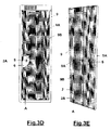
- Figure 3D is a front perspective view of the locker door showing the vertical round-shape ventilation perforations, the door shield and the multi-point lock.
- Figure 3E is a rear perspective view of the locker door showing the vertical round-shape ventilation perforations, the multi-point lock and the rounded fold.
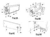
- Figure 4A is a rear perspective view of the locker door showing the storage compartment in the closed position and the multi-point lock therein.
- Figure 4B is a rear perspective view of the locker door showing the storage compartment in the open position and the multi-point lock therein.
- Figure 4C is a front perspective view of the locker door showing the multi-point lock for the storage compartment.
- Figure 4D is a detailed rear perspective view of the locker door showing the storage compartment in detail.
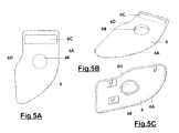
- Figure 5A is a front view of the locker door shield.
- Figure 5B is a front perspective view of the locker door shield.
- Figure 5C is a rear perspective view of the locker door shield.
-
- As can be inferred from the appended drawings that illustrate and integrate the present descriptive report of the patent for utility model of "Improvements Introduced in Multi-Purpose Lockers", the appended figures show the same in a general manner, comprising a complete and with proprietary characteristics multi-purpose locker (1) incorporating a set of devices and improvements in proprietary and specific structures of high durability and strength, made of metallic material or similar material having equal or higher lightness and strength, whose shapes and internal and external arrangements are properly arranged (fitted and attached) to the basis structure of the multi-purpose locker (1), the improvements comprising a differentiated design for the doors (2) formed by a rounded fold (2A) having a general curved shape creating a geometric shape similar to a pipe symmetrically arranged around the entire periphery of the door ends (A), so as to provide greater safety and finish to the door assembly (A) by eliminating sharp edges and comers; a round-shaped ventilation on the doors (3) formed by an upper (3A) and a lower (3B) assembly horizontally and symmetrically arranged parallel to the upper and lower ends, respectively, each possessing a set of perforations (3C) properly aligned to each other so as to form a general rectangular shape with the purpose of helping air circulation inside the multi-purpose locker (1); a storage compartment (4) having a general parallelepipedal shape and hollow on its upper face possessing a tab (4A) along the rear upper end, a small cutout (4B) having a rectangular shape centered on the right-hand side face and a rear flap (4C) having a general shape similar to an inverted "L" horizontally and symmetrically arranged between the door inner side (A) and along the rear lower end of the storage compartment (4), at this point by means of a hinge (4D), the lock (5) possessing a double inner catch (5A) in this configuration, one to be engaged on the door side (A) on the right and lock the latter and the other to be engaged on the small cutout (4B) on the left and lock the storage compartment (4) with the purpose of helping store objects with greater safety inside the multi-purpose locker (1); a multi-point type lock (5) having a general circular shape, a compact and robust shape in micro-cast stainless steel material or similar material with excellent mechanical strength bolted to the circular-shaped opening (B) of the door (A) of the multi-purpose locker (1) near the clear lateral side thereof and possessing a single or double inner catch (5A) with the purpose of generating greater safety and a differentiated configuration to the assembly thereof; and a door shield (6) having a general rectangular shape possessing a sweep (6A) along the right-hand side, a central opening (6B) having a circular shape, an upper recess (6C) having a rectangular shape and a small cutout (6D) along the upper side of the left-hand lateral side, being the shield vertically fitted under pressure to the door (A) opening (B) of the multi-purpose locker (1), around the lock (5), with the purpose of safekeeping and identifying the multi-purpose locker (1).
- The improvements introduced in multi-purpose lockers, according to the use needs and as shown in Figure (3B), can comprise a square-shaped ventilation on the doors (7), formed by an upper (7A) and a lower (7B) assembly horizontally and symmetrically arranged parallel to the upper and lower ends, respectively, each possessing a set of small perforations (7C) having general square shapes properly aligned to each other so as to form a rectangular shape with the purpose of helping air circulation inside the multi-purpose locker (1).
- The improvements introduced in multi-purpose lockers, according to the use needs and as shown in Figure (3C), can comprise a louver ventilation system on the doors (8), formed by an upper louver assembly (8A) horizontally and symmetrically arranged parallel to each other and to the upper end, each possessing an inner cutout having a rectangular shape and a front flap (8B) having a curved shape along the front side of the inner cutout with the purpose of helping air circulation inside the multi-purpose locker (1).
- The improvements introduced in multi-purpose lockers, according to the use needs and as shown in Figures (3D) and (3E), can comprise a vertical round-shaped ventilation on the doors (9), formed by a central assembly (9A) vertically and symmetrically arranged along one of the sides of the door (A) front side, possessing a set of perforations (9B) properly aligned to each other so as to create a rectangular shape with the purpose of helping air circulation inside the multi-purpose locker (1).
- The components of the improvements introduced in multi-purpose lockers are fully fitted and attached, are quickly installed and/or removed, do not present any distorting or breakable parts, are highly resistant and completely safe. After fitted and attached to the structure of the multi-purpose locker (1), the components are locked and attached, thus preventing them from getting loose or breaking when in use, thus making the assembly fully available for a better utilization of the multi-purpose locker by the users. Therefore, the multi-purpose locker (1) can be easily used without worries of any nature as regarding its durability and safety.
- As their structure are made of metallic material or similar material with equal of higher lightness and strength, the improvements introduced in multi-purpose lockers and the components thereof, are rustproof and waterproof, have a high level of durability and strength, provide great safety and, when routinely used in the multi-purpose lockers (1), do not present any risks of fatigue or to the users.
- For all of the above, this is an invention that will be well received by users and companies employing lockers to store several types of objects in general, since the present improvements introduced in multi-purpose lockers present several advantages, such as: great safety, reliability and agility; great resistance and general durability, as well as a low or no wear of the assembly as a whole; greater comfort, facility and safety to the users; great efficiency and performance in its use due to its general conception; fully accessible costs, which provides an optimum cost/benefit ratio; practical and safe use by any users, regardless of the characteristics thereof; great mobility and flexibility; low weight and general dimensions; attractive and modem design; practical and safe assembly and installation; general arrangements that do not upset the multi-purpose locker normal operation (1); and the certainty of always having a multi-purpose locker (1) to store the most varied products that fully meets the basic ergonomic, safety, strength and durability conditions required for its use.
- For all of the above, the improvements introduced in multi-purpose lockers can be classified as a fully versatile, efficient, practical and safe set of means to allow a better utilization of multi-purpose lockers (1) in the most varied places and for various users, regardless of the general characteristics thereof, being easily installed and handled, as well as having excellent general characteristics; the sizes, dimensions and quantities may vary, depending on the use needs.
Claims (9)
- "IMPROVEMENTS INTRODUCED IN MULTI-PURPOSE LOCKERS", characterized in that it comprises a complete multi-purpose locker (1) incorporating an set of devices and improvements in proprietary and specific structures of high durability and strength, made of metallic material or similar material with equal or higher lightness and strength, whose shapes and internal and external arrangements are properly arranged (fitted and attached) to the basis structure of multi-purpose lockers (1).
- "IMPROVEMENTS INTRODUCED IN MULTI-PURPOSE LOCKERS", in accordance with claim 1, characterized in that it incorporates a differentiated design for the doors (2) formed by a rounded fold (2A) having a general curved shape creating a geometric shape similar to a pipe symmetrically arranged around the entire periphery of the door (A) ends to eliminate sharp edges and comers.
- "IMPROVEMENTS INTRODUCED IN MULTI-PURPOSE LOCKERS", in accordance with claim 1, characterized in that it incorporates a round-shaped ventilation on the doors (3), formed by an upper (3A) and a lower (3B) assembly horizontally and symmetrically arranged parallel to the upper and lower ends, respectively, each possessing a set of perforations (3C) properly aligned to each other so as to form a rectangular shape.
- "IMPROVEMENTS INTRODUCED IN MULTI-PURPOSE LOCKERS", in accordance with claim 1, characterized in that it incorporates a storage compartment (4) having a general parallelepipedal shape and hollow on its upper face possessing a tab (4A) along the rear upper end, a small cutout (4B) having a rectangular shape centered on the right-hand side face and a rear flap (4C) with a shape similar to an inverted "L" horizontally and symmetrically attached between the door (A) inner side and along the rear lower end of the storage compartment (4), at this point by means of a hinge (4D), the lock (5) possessing an inner double catch (5A) in this configuration, one to be engaged on the door side (A) on the right and the other to be engaged on the small cutout (4B) on the left.
- "IMPROVEMENTS INTRODUCED IN MULTI-PURPOSE LOCKERS", in accordance with claim 1, characterized in that it incorporates a multi-point type lock (5) having a general circular shape, a compact and robust shape in micro-cast stainless steel material or similar material with excellent mechanical strength bolted to the circular shaped opening (B) of the door (A) of the multi-purpose locker (1), near the clear lateral side thereof and possessing an inner single or double catch (5A).
- "IMPROVEMENTS INTRODUCED IN MULTI-PURPOSE LOCKERS", in accordance with claim 1, characterized in that it incorporates a door shield (6) having a general rectangular shape possessing a sweep (6A) along the right-hand side, a central opening (6B) with circular shape, an upper recess (6C) having a rectangular shape and a small cutout (6D) along the upper side of the left-hand lateral side, being the shield vertically fitted under pressure to the door (A) opening (B) of the multi-purpose locker (1), around the lock (5).
- "IMPROVEMENTS INTRODUCED IN MULTI-PURPOSE LOCKERS", in accordance with claim 1, characterized in that it incorporates a square-shaped ventilation on the doors (7), formed by an upper (7A) and a lower (7B) assembly horizontally and symmetrically arranged parallel to the upper and lower ends, respectively, each possessing a set of small perforations (7C) having general square shapes properly aligned to each other so as to form a rectangular shape.
- "IMPROVEMENTS INTRODUCED IN MULTI-PURPOSE LOCKERS", in accordance with claim, characterized in that it incorporates a louver ventilation system on the doors (8), formed by an upper louver assembly (8A) horizontally and symmetrically parallel to each other and to the upper end, each possessing an inner cutout having a rectangular shape and a front flap (8B) having a curved shape along the front side of the inner cutout with the purpose of helping air circulation inside the multi-purpose locker (1).
- "IMPROVEMENTS INTRODUCED IN MULTI-PURPOSE LOCKERS", in accordance with claim 1, characterized in that it incorporates a vertical round-shaped ventilation on the doors (9), formed by a central assembly (9A) vertically and symmetrically arranged along one of the sides of the door (A) front side possessing a set of holes (9B) properly aligned to each other so as to form a rectangular shape.
Priority Applications (1)
| Application Number | Priority Date | Filing Date | Title |
|---|---|---|---|
| PL04024804T PL1525822T3 (en) | 2003-10-22 | 2004-10-19 | Improvements introduced in multi-purpose lockers |
Applications Claiming Priority (2)
| Application Number | Priority Date | Filing Date | Title |
|---|---|---|---|
| BRMU8302739-4U BR8302739Y1 (en) | 2003-10-22 | 2003-10-22 | Improvements introduced in multi-purpose cabinets. |
| BR8302739U | 2003-10-22 |
Publications (2)
| Publication Number | Publication Date |
|---|---|
| EP1525822A1 true EP1525822A1 (en) | 2005-04-27 |
| EP1525822B1 EP1525822B1 (en) | 2010-04-28 |
Family
ID=34383821
Family Applications (1)
| Application Number | Title | Priority Date | Filing Date |
|---|---|---|---|
| EP04024804A Expired - Lifetime EP1525822B1 (en) | 2003-10-22 | 2004-10-19 | Improvements introduced in multi-purpose lockers |
Country Status (8)
| Country | Link |
|---|---|
| US (1) | US20050088065A1 (en) |
| EP (1) | EP1525822B1 (en) |
| AT (1) | ATE465655T1 (en) |
| BR (1) | BR8302739Y1 (en) |
| DE (1) | DE602004026811D1 (en) |
| ES (1) | ES2345387T3 (en) |
| PL (1) | PL1525822T3 (en) |
| PT (1) | PT1525822E (en) |
Citations (5)
| Publication number | Priority date | Publication date | Assignee | Title |
|---|---|---|---|---|
| DE360666C (en) * | 1919-09-23 | 1922-10-05 | Carl Friedrich Maasz | Wardrobe with several drums arranged in a row, rotatable about their standing longitudinal axis and circular in cross section |
| DE9419729U1 (en) * | 1994-12-09 | 1995-04-06 | Koukal, René, 90425 Nürnberg | Locker made of metal |
| US5810458A (en) * | 1994-02-10 | 1998-09-22 | Compression Polymers Group | Locker door retrofit assembly |
| US20030127956A1 (en) * | 1998-06-17 | 2003-07-10 | Sandusky Cabinets, Inc. | Cabinet |
| EP1415573A2 (en) * | 2002-09-19 | 2004-05-06 | Nilko Metalurgia, Ltda. | Purpouse lockers |
Family Cites Families (32)
| Publication number | Priority date | Publication date | Assignee | Title |
|---|---|---|---|---|
| US559744A (en) * | 1896-05-05 | Folding kitchen toilet-stand | ||
| US1340377A (en) * | 1919-08-30 | 1920-05-18 | Charles M Cott | Household safety-deposit box |
| US1883785A (en) * | 1929-06-24 | 1932-10-18 | Bertram C Hamm | Desk adjunct |
| US2012262A (en) * | 1933-11-22 | 1935-08-27 | Westinghouse Electric & Mfg Co | Refrigeration apparatus |
| US2269940A (en) * | 1939-01-30 | 1942-01-13 | Henry J Johnson | Storage device |
| US2636800A (en) * | 1949-04-15 | 1953-04-28 | William H J Downey | Combined linen closet and clothes hamper |
| US2825219A (en) * | 1953-06-04 | 1958-03-04 | Paul A Marzillier | Door latch and recessed operator |
| US2859595A (en) * | 1954-03-25 | 1958-11-11 | Gen Motors Corp | Two temperature refrigerator with forced air circulation |
| US2946640A (en) * | 1954-07-30 | 1960-07-26 | Aurora Equipment Co | Locker handle construction |
| US3000681A (en) * | 1957-09-12 | 1961-09-19 | John C Long | Waste receptacle |
| US2912271A (en) * | 1957-10-28 | 1959-11-10 | Interior Steel Equipment Compa | Door latch mechanism |
| US3133772A (en) * | 1960-12-20 | 1964-05-19 | Ekco Products Company | Locker |
| US3146739A (en) * | 1962-07-27 | 1964-09-01 | Furman Murray | Combination of strongbox and anchoring means |
| US3742742A (en) * | 1971-08-25 | 1973-07-03 | Master Lock Co | Inset lock for lockers and the like |
| US3920297A (en) * | 1974-10-11 | 1975-11-18 | Brandes Enterprises Inc | Locker units |
| US4001970A (en) * | 1975-02-11 | 1977-01-11 | Akio Miyamoto | Closable counter device for vertical wall |
| US4037896A (en) * | 1975-10-30 | 1977-07-26 | Lincoln Manufacturing Company, Inc. | Tray slide and support therefor |
| US4163592A (en) * | 1977-10-12 | 1979-08-07 | George Nelson & Company | Furniture units with L-shaped panel supports |
| US4283099A (en) * | 1979-07-16 | 1981-08-11 | Waters Instruments, Inc. | Locker cabinet |
| US4288132A (en) * | 1980-02-19 | 1981-09-08 | Roper Corporation | Metal cabinet for assembly by the user from knocked-down condition |
| US4369993A (en) * | 1980-10-17 | 1983-01-25 | Rodriguez Luis A | Door locking device for use with interchangeable padlocks |
| US4541675A (en) * | 1981-07-21 | 1985-09-17 | Tusco Manufacturing Co. | Display canopy |
| US4537451A (en) * | 1983-04-13 | 1985-08-27 | Theodore Bredderman | Hanging locker shelves |
| US4987836A (en) * | 1988-11-04 | 1991-01-29 | Owen John S | Safes |
| US5372415A (en) * | 1993-05-18 | 1994-12-13 | Suncast Corporation | Thermoplastic locker construction |
| US5470115A (en) * | 1994-02-10 | 1995-11-28 | Debourgh Manufacturing Company | Recessed three-point latching mechanism and method for a storage locker |
| AT404219B (en) * | 1995-01-19 | 1998-09-25 | Blum Gmbh Julius | DRAWER |
| KR0136407B1 (en) * | 1995-08-04 | 1998-07-01 | 배순훈 | Door pocket of a refrigerator |
| US5711491A (en) * | 1995-12-19 | 1998-01-27 | Dart Industries Inc. | Food grater |
| US5870910A (en) * | 1996-12-02 | 1999-02-16 | Block And Company, Inc. | Lock-down security box |
| US6457788B1 (en) * | 2000-10-04 | 2002-10-01 | Compaq Information Technologies Group, L.P. | Computer hood latching system |
| US6742855B2 (en) * | 2001-11-30 | 2004-06-01 | General Electric Company | Freezer tip out bin |
-
2003
- 2003-10-22 BR BRMU8302739-4U patent/BR8302739Y1/en not_active IP Right Cessation
-
2004
- 2004-10-19 PT PT04024804T patent/PT1525822E/en unknown
- 2004-10-19 EP EP04024804A patent/EP1525822B1/en not_active Expired - Lifetime
- 2004-10-19 PL PL04024804T patent/PL1525822T3/en unknown
- 2004-10-19 ES ES04024804T patent/ES2345387T3/en not_active Expired - Lifetime
- 2004-10-19 AT AT04024804T patent/ATE465655T1/en active
- 2004-10-19 DE DE602004026811T patent/DE602004026811D1/en not_active Expired - Lifetime
- 2004-11-28 US US10/904,769 patent/US20050088065A1/en not_active Abandoned
Patent Citations (5)
| Publication number | Priority date | Publication date | Assignee | Title |
|---|---|---|---|---|
| DE360666C (en) * | 1919-09-23 | 1922-10-05 | Carl Friedrich Maasz | Wardrobe with several drums arranged in a row, rotatable about their standing longitudinal axis and circular in cross section |
| US5810458A (en) * | 1994-02-10 | 1998-09-22 | Compression Polymers Group | Locker door retrofit assembly |
| DE9419729U1 (en) * | 1994-12-09 | 1995-04-06 | Koukal, René, 90425 Nürnberg | Locker made of metal |
| US20030127956A1 (en) * | 1998-06-17 | 2003-07-10 | Sandusky Cabinets, Inc. | Cabinet |
| EP1415573A2 (en) * | 2002-09-19 | 2004-05-06 | Nilko Metalurgia, Ltda. | Purpouse lockers |
Also Published As
| Publication number | Publication date |
|---|---|
| EP1525822B1 (en) | 2010-04-28 |
| US20050088065A1 (en) | 2005-04-28 |
| PL1525822T3 (en) | 2010-10-29 |
| DE602004026811D1 (en) | 2010-06-10 |
| BR8302739Y1 (en) | 2012-08-07 |
| ES2345387T3 (en) | 2010-09-22 |
| BR8302739U (en) | 2005-06-14 |
| ATE465655T1 (en) | 2010-05-15 |
| PT1525822E (en) | 2010-08-02 |
Similar Documents
| Publication | Publication Date | Title |
|---|---|---|
| US5357900A (en) | Portable cage for pets | |
| USD1001615S1 (en) | Lock escutcheon | |
| USD674266S1 (en) | Cable shackle padlock having a sidewall aperture for a status indicator | |
| USD545099S1 (en) | Bathroom organizer | |
| US6832689B2 (en) | Tool box having expandable drawers | |
| US20160237717A1 (en) | Pocket Door Pull Devices | |
| US3637246A (en) | Latching mechanism | |
| USD533763S1 (en) | Lock | |
| EP1525822B1 (en) | Improvements introduced in multi-purpose lockers | |
| USD446378S1 (en) | Letter box | |
| CN207836975U (en) | In preceding face, there are two the trolley cases uncapped | |
| US1683218A (en) | Mail box | |
| USD490041S1 (en) | Boat hatch | |
| DE102018204911A1 (en) | Domestic appliance with a sensor unit arranged on a closure element | |
| WO2018041230A1 (en) | Suitcase | |
| KR20110022836A (en) | Locker handle | |
| EP1415573B1 (en) | Purpouse lockers | |
| USD509979S1 (en) | Storage device | |
| USD419303S (en) | Customizable luggage identification and personalization handle cover | |
| CN207004241U (en) | One kind lock and rack | |
| CN209355372U (en) | A kind of air-conditioning for preventing copper pipe from losing | |
| CN202425773U (en) | Portable resin suitcase | |
| JP4017618B2 (en) | Multi-person locker | |
| CN211092731U (en) | High school campus student valuables management cabinet | |
| CN210370211U (en) | Waterproof door lock box |
Legal Events
| Date | Code | Title | Description |
|---|---|---|---|
| PUAI | Public reference made under article 153(3) epc to a published international application that has entered the european phase |
Free format text: ORIGINAL CODE: 0009012 |
|
| AK | Designated contracting states |
Kind code of ref document: A1 Designated state(s): AT BE BG CH CY CZ DE DK EE ES FI FR GB GR HU IE IT LI LU MC NL PL PT RO SE SI SK TR |
|
| AX | Request for extension of the european patent |
Extension state: AL HR LT LV MK |
|
| 17P | Request for examination filed |
Effective date: 20051020 |
|
| AKX | Designation fees paid |
Designated state(s): AT BE BG CH CY CZ DE DK EE ES FI FR GB GR HU IE IT LI LU MC NL PL PT RO SE SI SK TR |
|
| 17Q | First examination report despatched |
Effective date: 20060407 |
|
| GRAP | Despatch of communication of intention to grant a patent |
Free format text: ORIGINAL CODE: EPIDOSNIGR1 |
|
| RIN1 | Information on inventor provided before grant (corrected) |
Inventor name: HUSCHER, FRAIMUNDO |
|
| GRAS | Grant fee paid |
Free format text: ORIGINAL CODE: EPIDOSNIGR3 |
|
| GRAA | (expected) grant |
Free format text: ORIGINAL CODE: 0009210 |
|
| AK | Designated contracting states |
Kind code of ref document: B1 Designated state(s): AT BE BG CH CY CZ DE DK EE ES FI FR GB GR HU IE IT LI LU MC NL PL PT RO SE SI SK TR |
|
| REG | Reference to a national code |
Ref country code: GB Ref legal event code: FG4D |
|
| REG | Reference to a national code |
Ref country code: CH Ref legal event code: EP |
|
| REG | Reference to a national code |
Ref country code: IE Ref legal event code: FG4D |
|
| REF | Corresponds to: |
Ref document number: 602004026811 Country of ref document: DE Date of ref document: 20100610 Kind code of ref document: P |
|
| REG | Reference to a national code |
Ref country code: RO Ref legal event code: EPE |
|
| REG | Reference to a national code |
Ref country code: CH Ref legal event code: NV Representative=s name: INDUSTRIEBERATUNG MAIER AG |
|
| REG | Reference to a national code |
Ref country code: PT Ref legal event code: SC4A Free format text: AVAILABILITY OF NATIONAL TRANSLATION Effective date: 20100727 |
|
| REG | Reference to a national code |
Ref country code: NL Ref legal event code: T3 |
|
| REG | Reference to a national code |
Ref country code: GR Ref legal event code: EP Ref document number: 20100401818 Country of ref document: GR |
|
| REG | Reference to a national code |
Ref country code: ES Ref legal event code: FG2A Ref document number: 2345387 Country of ref document: ES Kind code of ref document: T3 |
|
| PG25 | Lapsed in a contracting state [announced via postgrant information from national office to epo] |
Ref country code: SE Free format text: LAPSE BECAUSE OF FAILURE TO SUBMIT A TRANSLATION OF THE DESCRIPTION OR TO PAY THE FEE WITHIN THE PRESCRIBED TIME-LIMIT Effective date: 20100428 |
|
| REG | Reference to a national code |
Ref country code: PL Ref legal event code: T3 |
|
| PG25 | Lapsed in a contracting state [announced via postgrant information from national office to epo] |
Ref country code: SI Free format text: LAPSE BECAUSE OF FAILURE TO SUBMIT A TRANSLATION OF THE DESCRIPTION OR TO PAY THE FEE WITHIN THE PRESCRIBED TIME-LIMIT Effective date: 20100428 Ref country code: FI Free format text: LAPSE BECAUSE OF FAILURE TO SUBMIT A TRANSLATION OF THE DESCRIPTION OR TO PAY THE FEE WITHIN THE PRESCRIBED TIME-LIMIT Effective date: 20100428 |
|
| PG25 | Lapsed in a contracting state [announced via postgrant information from national office to epo] |
Ref country code: CY Free format text: LAPSE BECAUSE OF FAILURE TO SUBMIT A TRANSLATION OF THE DESCRIPTION OR TO PAY THE FEE WITHIN THE PRESCRIBED TIME-LIMIT Effective date: 20100428 |
|
| PGFP | Annual fee paid to national office [announced via postgrant information from national office to epo] |
Ref country code: GR Payment date: 20100729 Year of fee payment: 7 |
|
| REG | Reference to a national code |
Ref country code: HU Ref legal event code: AG4A Ref document number: E008904 Country of ref document: HU |
|
| PG25 | Lapsed in a contracting state [announced via postgrant information from national office to epo] |
Ref country code: EE Free format text: LAPSE BECAUSE OF FAILURE TO SUBMIT A TRANSLATION OF THE DESCRIPTION OR TO PAY THE FEE WITHIN THE PRESCRIBED TIME-LIMIT Effective date: 20100428 Ref country code: DK Free format text: LAPSE BECAUSE OF FAILURE TO SUBMIT A TRANSLATION OF THE DESCRIPTION OR TO PAY THE FEE WITHIN THE PRESCRIBED TIME-LIMIT Effective date: 20100428 |
|
| PGFP | Annual fee paid to national office [announced via postgrant information from national office to epo] |
Ref country code: AT Payment date: 20101008 Year of fee payment: 7 Ref country code: FR Payment date: 20101112 Year of fee payment: 7 Ref country code: IE Payment date: 20101029 Year of fee payment: 7 Ref country code: NL Payment date: 20101029 Year of fee payment: 7 |
|
| PG25 | Lapsed in a contracting state [announced via postgrant information from national office to epo] |
Ref country code: SK Free format text: LAPSE BECAUSE OF FAILURE TO SUBMIT A TRANSLATION OF THE DESCRIPTION OR TO PAY THE FEE WITHIN THE PRESCRIBED TIME-LIMIT Effective date: 20100428 |
|
| PGFP | Annual fee paid to national office [announced via postgrant information from national office to epo] |
Ref country code: BG Payment date: 20101014 Year of fee payment: 7 Ref country code: CH Payment date: 20101201 Year of fee payment: 7 Ref country code: CZ Payment date: 20101015 Year of fee payment: 7 Ref country code: DE Payment date: 20101012 Year of fee payment: 7 Ref country code: HU Payment date: 20101014 Year of fee payment: 7 Ref country code: PL Payment date: 20101006 Year of fee payment: 7 Ref country code: RO Payment date: 20101013 Year of fee payment: 7 |
|
| PLBE | No opposition filed within time limit |
Free format text: ORIGINAL CODE: 0009261 |
|
| STAA | Information on the status of an ep patent application or granted ep patent |
Free format text: STATUS: NO OPPOSITION FILED WITHIN TIME LIMIT |
|
| PGFP | Annual fee paid to national office [announced via postgrant information from national office to epo] |
Ref country code: TR Payment date: 20101013 Year of fee payment: 7 Ref country code: IT Payment date: 20101006 Year of fee payment: 7 Ref country code: GB Payment date: 20101007 Year of fee payment: 7 Ref country code: BE Payment date: 20101105 Year of fee payment: 7 |
|
| 26N | No opposition filed |
Effective date: 20110131 |
|
| PG25 | Lapsed in a contracting state [announced via postgrant information from national office to epo] |
Ref country code: MC Free format text: LAPSE BECAUSE OF NON-PAYMENT OF DUE FEES Effective date: 20101031 |
|
| PGFP | Annual fee paid to national office [announced via postgrant information from national office to epo] |
Ref country code: ES Payment date: 20101007 Year of fee payment: 7 |
|
| BERE | Be: lapsed |
Owner name: NILKO METALURGIA, LTDA. Effective date: 20111031 |
|
| REG | Reference to a national code |
Ref country code: NL Ref legal event code: V1 Effective date: 20120501 |
|
| REG | Reference to a national code |
Ref country code: CH Ref legal event code: PL |
|
| REG | Reference to a national code |
Ref country code: GR Ref legal event code: ML Ref document number: 20100401818 Country of ref document: GR Effective date: 20120503 |
|
| GBPC | Gb: european patent ceased through non-payment of renewal fee |
Effective date: 20111019 |
|
| REG | Reference to a national code |
Ref country code: FR Ref legal event code: ST Effective date: 20120629 |
|
| PG25 | Lapsed in a contracting state [announced via postgrant information from national office to epo] |
Ref country code: HU Free format text: LAPSE BECAUSE OF NON-PAYMENT OF DUE FEES Effective date: 20111020 Ref country code: DE Free format text: LAPSE BECAUSE OF NON-PAYMENT OF DUE FEES Effective date: 20120501 Ref country code: LI Free format text: LAPSE BECAUSE OF NON-PAYMENT OF DUE FEES Effective date: 20111031 Ref country code: CH Free format text: LAPSE BECAUSE OF NON-PAYMENT OF DUE FEES Effective date: 20111031 Ref country code: CZ Free format text: LAPSE BECAUSE OF NON-PAYMENT OF DUE FEES Effective date: 20111019 Ref country code: BE Free format text: LAPSE BECAUSE OF NON-PAYMENT OF DUE FEES Effective date: 20111031 Ref country code: NL Free format text: LAPSE BECAUSE OF NON-PAYMENT OF DUE FEES Effective date: 20120501 |
|
| REG | Reference to a national code |
Ref country code: IE Ref legal event code: MM4A |
|
| REG | Reference to a national code |
Ref country code: DE Ref legal event code: R119 Ref document number: 602004026811 Country of ref document: DE Effective date: 20120501 |
|
| PG25 | Lapsed in a contracting state [announced via postgrant information from national office to epo] |
Ref country code: IT Free format text: LAPSE BECAUSE OF NON-PAYMENT OF DUE FEES Effective date: 20111019 Ref country code: GB Free format text: LAPSE BECAUSE OF NON-PAYMENT OF DUE FEES Effective date: 20111019 Ref country code: FR Free format text: LAPSE BECAUSE OF NON-PAYMENT OF DUE FEES Effective date: 20111102 Ref country code: GR Free format text: LAPSE BECAUSE OF NON-PAYMENT OF DUE FEES Effective date: 20120503 |
|
| PG25 | Lapsed in a contracting state [announced via postgrant information from national office to epo] |
Ref country code: LU Free format text: LAPSE BECAUSE OF NON-PAYMENT OF DUE FEES Effective date: 20101019 |
|
| PG25 | Lapsed in a contracting state [announced via postgrant information from national office to epo] |
Ref country code: IE Free format text: LAPSE BECAUSE OF NON-PAYMENT OF DUE FEES Effective date: 20111019 |
|
| REG | Reference to a national code |
Ref country code: AT Ref legal event code: MM01 Ref document number: 465655 Country of ref document: AT Kind code of ref document: T Effective date: 20111019 |
|
| PG25 | Lapsed in a contracting state [announced via postgrant information from national office to epo] |
Ref country code: AT Free format text: LAPSE BECAUSE OF NON-PAYMENT OF DUE FEES Effective date: 20111019 |
|
| REG | Reference to a national code |
Ref country code: PL Ref legal event code: LAPE |
|
| PG25 | Lapsed in a contracting state [announced via postgrant information from national office to epo] |
Ref country code: PL Free format text: LAPSE BECAUSE OF NON-PAYMENT OF DUE FEES Effective date: 20111019 |
|
| PGFP | Annual fee paid to national office [announced via postgrant information from national office to epo] |
Ref country code: PT Payment date: 20120420 Year of fee payment: 9 |
|
| REG | Reference to a national code |
Ref country code: ES Ref legal event code: FD2A Effective date: 20130417 |
|
| PG25 | Lapsed in a contracting state [announced via postgrant information from national office to epo] |
Ref country code: ES Free format text: LAPSE BECAUSE OF NON-PAYMENT OF DUE FEES Effective date: 20111020 |
|
| PG25 | Lapsed in a contracting state [announced via postgrant information from national office to epo] |
Ref country code: BG Free format text: LAPSE BECAUSE OF NON-PAYMENT OF DUE FEES Effective date: 20120630 |
|
| PG25 | Lapsed in a contracting state [announced via postgrant information from national office to epo] |
Ref country code: TR Free format text: LAPSE BECAUSE OF NON-PAYMENT OF DUE FEES Effective date: 20111019 |
|
| REG | Reference to a national code |
Ref country code: PT Ref legal event code: MM4A Free format text: LAPSE DUE TO NON-PAYMENT OF FEES Effective date: 20140421 |
|
| PG25 | Lapsed in a contracting state [announced via postgrant information from national office to epo] |
Ref country code: RO Free format text: LAPSE BECAUSE OF NON-PAYMENT OF DUE FEES Effective date: 20131019 Ref country code: PT Free format text: LAPSE BECAUSE OF NON-PAYMENT OF DUE FEES Effective date: 20140421 |