US5810458A - Locker door retrofit assembly - Google Patents
Locker door retrofit assembly Download PDFInfo
- Publication number
- US5810458A US5810458A US08/754,496 US75449696A US5810458A US 5810458 A US5810458 A US 5810458A US 75449696 A US75449696 A US 75449696A US 5810458 A US5810458 A US 5810458A
- Authority
- US
- United States
- Prior art keywords
- door
- locker
- assembly
- existing
- hinge
- Prior art date
- Legal status (The legal status is an assumption and is not a legal conclusion. Google has not performed a legal analysis and makes no representation as to the accuracy of the status listed.)
- Expired - Lifetime
Links
- 238000000034 method Methods 0.000 claims description 13
- 238000009420 retrofitting Methods 0.000 claims 3
- 229920001903 high density polyethylene Polymers 0.000 claims 2
- 239000004700 high-density polyethylene Substances 0.000 claims 2
- 239000004033 plastic Substances 0.000 abstract description 17
- 229920003023 plastic Polymers 0.000 abstract description 17
- 230000000712 assembly Effects 0.000 abstract description 9
- 238000000429 assembly Methods 0.000 abstract description 9
- 239000000463 material Substances 0.000 description 14
- 229910052751 metal Inorganic materials 0.000 description 8
- 239000002184 metal Substances 0.000 description 8
- 230000008901 benefit Effects 0.000 description 4
- 229910000831 Steel Inorganic materials 0.000 description 3
- 238000010276 construction Methods 0.000 description 3
- 238000009434 installation Methods 0.000 description 3
- 239000010959 steel Substances 0.000 description 3
- 239000004698 Polyethylene Substances 0.000 description 2
- 230000000386 athletic effect Effects 0.000 description 2
- -1 polyethylene Polymers 0.000 description 2
- 229920000573 polyethylene Polymers 0.000 description 2
- 239000002023 wood Substances 0.000 description 2
- 229910052782 aluminium Inorganic materials 0.000 description 1
- XAGFODPZIPBFFR-UHFFFAOYSA-N aluminium Chemical compound [Al] XAGFODPZIPBFFR-UHFFFAOYSA-N 0.000 description 1
- 239000003086 colorant Substances 0.000 description 1
- 239000002131 composite material Substances 0.000 description 1
- 239000004035 construction material Substances 0.000 description 1
- 239000002537 cosmetic Substances 0.000 description 1
- 230000032798 delamination Effects 0.000 description 1
- 238000005562 fading Methods 0.000 description 1
- JEIPFZHSYJVQDO-UHFFFAOYSA-N iron(III) oxide Inorganic materials O=[Fe]O[Fe]=O JEIPFZHSYJVQDO-UHFFFAOYSA-N 0.000 description 1
- 239000007769 metal material Substances 0.000 description 1
- 238000012986 modification Methods 0.000 description 1
- 230000004048 modification Effects 0.000 description 1
- 229910052755 nonmetal Inorganic materials 0.000 description 1
- 235000019645 odor Nutrition 0.000 description 1
- 229910001220 stainless steel Inorganic materials 0.000 description 1
- 239000010935 stainless steel Substances 0.000 description 1
- 239000000126 substance Substances 0.000 description 1
- 238000006467 substitution reaction Methods 0.000 description 1
- 230000009182 swimming Effects 0.000 description 1
- 230000007704 transition Effects 0.000 description 1
Images


Classifications
-
- A—HUMAN NECESSITIES
- A47—FURNITURE; DOMESTIC ARTICLES OR APPLIANCES; COFFEE MILLS; SPICE MILLS; SUCTION CLEANERS IN GENERAL
- A47B—TABLES; DESKS; OFFICE FURNITURE; CABINETS; DRAWERS; GENERAL DETAILS OF FURNITURE
- A47B47/00—Cabinets, racks or shelf units, characterised by features related to dismountability or building-up from elements
- A47B47/0025—Horizontal connecting members adapted to receive and retain the edges of several panel elements
- A47B47/0033—Corners
-
- A—HUMAN NECESSITIES
- A47—FURNITURE; DOMESTIC ARTICLES OR APPLIANCES; COFFEE MILLS; SPICE MILLS; SUCTION CLEANERS IN GENERAL
- A47B—TABLES; DESKS; OFFICE FURNITURE; CABINETS; DRAWERS; GENERAL DETAILS OF FURNITURE
- A47B47/00—Cabinets, racks or shelf units, characterised by features related to dismountability or building-up from elements
- A47B47/02—Cabinets, racks or shelf units, characterised by features related to dismountability or building-up from elements made of metal only
-
- A—HUMAN NECESSITIES
- A47—FURNITURE; DOMESTIC ARTICLES OR APPLIANCES; COFFEE MILLS; SPICE MILLS; SUCTION CLEANERS IN GENERAL
- A47B—TABLES; DESKS; OFFICE FURNITURE; CABINETS; DRAWERS; GENERAL DETAILS OF FURNITURE
- A47B61/00—Wardrobes
-
- A—HUMAN NECESSITIES
- A47—FURNITURE; DOMESTIC ARTICLES OR APPLIANCES; COFFEE MILLS; SPICE MILLS; SUCTION CLEANERS IN GENERAL
- A47B—TABLES; DESKS; OFFICE FURNITURE; CABINETS; DRAWERS; GENERAL DETAILS OF FURNITURE
- A47B96/00—Details of cabinets, racks or shelf units not covered by a single one of groups A47B43/00 - A47B95/00; General details of furniture
-
- E—FIXED CONSTRUCTIONS
- E05—LOCKS; KEYS; WINDOW OR DOOR FITTINGS; SAFES
- E05C—BOLTS OR FASTENING DEVICES FOR WINGS, SPECIALLY FOR DOORS OR WINDOWS
- E05C3/00—Fastening devices with bolts moving pivotally or rotatively
- E05C3/02—Fastening devices with bolts moving pivotally or rotatively without latching action
- E05C3/04—Fastening devices with bolts moving pivotally or rotatively without latching action with operating handle or equivalent member rigid with the bolt
- E05C3/047—Fastening devices with bolts moving pivotally or rotatively without latching action with operating handle or equivalent member rigid with the bolt rotating about an axis parallel to the surface on which the fastener is mounted
- E05C3/048—Fastening devices with bolts moving pivotally or rotatively without latching action with operating handle or equivalent member rigid with the bolt rotating about an axis parallel to the surface on which the fastener is mounted parallel to the wing edge
-
- E—FIXED CONSTRUCTIONS
- E05—LOCKS; KEYS; WINDOW OR DOOR FITTINGS; SAFES
- E05D—HINGES OR SUSPENSION DEVICES FOR DOORS, WINDOWS OR WINGS
- E05D5/00—Construction of single parts, e.g. the parts for attachment
- E05D5/02—Parts for attachment, e.g. flaps
- E05D5/06—Bent flaps
- E05D5/065—Bent flaps specially adapted for cabinets or furniture
-
- F—MECHANICAL ENGINEERING; LIGHTING; HEATING; WEAPONS; BLASTING
- F16—ENGINEERING ELEMENTS AND UNITS; GENERAL MEASURES FOR PRODUCING AND MAINTAINING EFFECTIVE FUNCTIONING OF MACHINES OR INSTALLATIONS; THERMAL INSULATION IN GENERAL
- F16B—DEVICES FOR FASTENING OR SECURING CONSTRUCTIONAL ELEMENTS OR MACHINE PARTS TOGETHER, e.g. NAILS, BOLTS, CIRCLIPS, CLAMPS, CLIPS OR WEDGES; JOINTS OR JOINTING
- F16B12/00—Jointing of furniture or the like, e.g. hidden from exterior
- F16B12/10—Jointing of furniture or the like, e.g. hidden from exterior using pegs, bolts, tenons, clamps, clips, or the like
- F16B12/12—Jointing of furniture or the like, e.g. hidden from exterior using pegs, bolts, tenons, clamps, clips, or the like for non-metal furniture parts, e.g. made of wood, of plastics
- F16B12/26—Jointing of furniture or the like, e.g. hidden from exterior using pegs, bolts, tenons, clamps, clips, or the like for non-metal furniture parts, e.g. made of wood, of plastics using snap-action elements
-
- E—FIXED CONSTRUCTIONS
- E05—LOCKS; KEYS; WINDOW OR DOOR FITTINGS; SAFES
- E05D—HINGES OR SUSPENSION DEVICES FOR DOORS, WINDOWS OR WINGS
- E05D5/00—Construction of single parts, e.g. the parts for attachment
- E05D5/02—Parts for attachment, e.g. flaps
- E05D5/0215—Parts for attachment, e.g. flaps for attachment to profile members or the like
- E05D5/0223—Parts for attachment, e.g. flaps for attachment to profile members or the like with parts, e.g. screws, extending through the profile wall or engaging profile grooves
- E05D5/0238—Parts for attachment, e.g. flaps for attachment to profile members or the like with parts, e.g. screws, extending through the profile wall or engaging profile grooves with parts engaging profile grooves
-
- E—FIXED CONSTRUCTIONS
- E05—LOCKS; KEYS; WINDOW OR DOOR FITTINGS; SAFES
- E05Y—INDEXING SCHEME ASSOCIATED WITH SUBCLASSES E05D AND E05F, RELATING TO CONSTRUCTION ELEMENTS, ELECTRIC CONTROL, POWER SUPPLY, POWER SIGNAL OR TRANSMISSION, USER INTERFACES, MOUNTING OR COUPLING, DETAILS, ACCESSORIES, AUXILIARY OPERATIONS NOT OTHERWISE PROVIDED FOR, APPLICATION THEREOF
- E05Y2900/00—Application of doors, windows, wings or fittings thereof
- E05Y2900/20—Application of doors, windows, wings or fittings thereof for furniture, e.g. cabinets
Definitions
- the present invention relates generally to lockers and more particularly to locker door retrofit assemblies.
- the present invention is designed to replace existing metallic doors or other assemblies with a locker door assembly comprised of a more suitable material.
- Lockers for storing clothing, articles of merchandise, etc. are commonly constructed. Storage lockers are found in many different settings. For example, athletic facilities have lockers to allow athletes to store their possessions while participating in athletic events. Community swimming pools typically have lockers for storing street clothes while a person swims. Lockers are also found in industry where they are used for several purposes, such as the storage of equipment, work clothes, chemicals, and other items which are preferably kept in such a concealed environment when not in use. Lockers are also commonly found in airports, hospitals, school hallways, prisons, and many other sites too numerous to mention.
- Metallic lockers suffer from several disadvantages. They are easily damaged or marred such as by dents, scratches and graffiti. Moreover, the metal is subject to damage from rust, odors, delamination and fading.
- the present invention is a locker door retrofit assembly comprised of a material designed to overcome the above disadvantages, such as a plastic or a composite material.
- the following disclosure describes a plastic locker door retrofit assembly.
- any non-metal material that exhibits the desired characteristics may be utilized for the present invention.
- the locker door assembly Due to the plastic construction of the door assembly, the locker face will be resistant to many forms of abuse that lockers commonly receive. The locker doors will not dent as will metal lockers. In one embodiment, the locker door of the present invention will maintain its color throughout its entire cross-section. Due to the preferred homogeneous nature of the plastic door assembly, the lockers of the present invention will not delaminate. Furthermore, most materials used in the application of graffiti are readily removed from plastic panels to return the locker doors to their original surface appearance. The remaining metallic body of the locker system is hidden behind the plastic face and is thus protected. Moreover, the substitution with a plastic door assembly provides many cosmetic and aesthetically pleasing attributes to the locker system. These plastic lockers may carry almost any color scheme desirable. Colors may be chosen to match the surrounding decor, to provide a color coding scheme and/or to provide a medium for an organizational theme.
- the present invention may provide for a complete retrofit locker assembly which may be assembled off-site.
- the retrofit assembly may be shipped as one complete part and expeditiously attached to the old locker frame on-site. Accordingly, the locker assembly may be manufactured and assembled in a quality controlled factory environment which results in high quality, structurally sound, and consistent assemblies. Accordingly, the locker assemblies of the present invention may be installed on-site in a relatively short time while maintaining structural integrity and consistency.
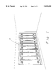
- FIG. 1 is a perspective view of one embodiment of the installed locker door retrofit assembly of the present invention on an in-wall locker system;
- FIG. 2 is a detail view of the trim along the top of the locker door retrofit assembly shown in FIG. 1;
- FIG. 3 is a section view taken along line 3--3 of FIG. 2;
- FIG. 4 is a top plan view of the door hinge of one embodiment of the present invention attached to the metallic locker wall;
- FIG. 5 is a top plan view of one embodiment of the jamb of the present invention attached to the metallic wall;
- FIG. 6 is a plan view of the door of one embodiment of the present invention.
- FIG. 7 is a detailed plan view of the door hinge of one embodiment of the present invention.
- FIG. 8 is a detailed plan view of the jamb hinge of one embodiment of the present invention.
- FIG. 9 is a detailed plan view of the door lock of one embodiment of the present invention.
- FIG. 10 is a detailed plan view of the jamb lock of one embodiment of the present invention.
- FIG. 11 is a perspective view of the preferred retrofit locker assembly of the present invention.
- FIG. 12 is a top plan view of the preferred retrofit locker assembly of the present invention.
- FIG. 13 is an exploded view of a preferred embodiment of the latching means and handle of the present invention.
- FIG. 1 shows one embodiment of the present invention installed on an in-wall locker system shown generally at 10.
- the following description and accompanying figures disclose a locker door assembly with a right-hand opening. It must be understood that the present invention also encompasses left-hand openings and that the knowledge to provide left-hand versus right hand openings, from the disclosure provided herein, would be readily apparent. Although existing metal lockers are well suited for retrofit with the present invention, lockers made of other materials would likewise benefit from the present invention.
- FIG. 2 shows generally the trim at the top of the plastic locker door at 20.
- a long strip of material 22 is fastened to wall 24 with fasteners shown generally at 26 to form the top trim 28.
- Top trim 28 serves to cosmetically and mechanically smooth the transition from the locker retrofit assembly 30 to the building walls 24.
- Fasteners, shown generally at 26, in the preferred embodiment include countersunk screws with matching caps, but any method of fastening the trim 28 to the wall 24 may be used.
- FIG. 3 shows a section view of one embodiment of the locker door retrofit assembly installed on an in-wall locker system at 40.
- the section of wall allows a view of the top of the existing metallic in-wall portions of a locker system at 44.
- the interface between the locker door retrofit assembly 30 and the in-wall locker system at 44 can be viewed at 48.
- FIG. 4 shows the installation of the jamb hinge on the in-wall locker at 52.
- Jamb hinge 54 may be placed against the right-sidewall of the in-wall locker at 56. Note, the configuration of the jamb hinge 54 allows open space to accommodate the existing hinge of the in-wall locker at 58, if so desired.
- Jamb hinge 54 is attached to the in-wall locker 56 with fasteners shown generally at 60.
- Jamb lock 64 is placed against the left-sidewall of the in-wall locker 66 and fastened thereto with a fastener shown generally at 68.
- the jamb lock 64 is preferably adapted to be slidably adjustable in relation to the jamb hinge 54, prior to securing the jamb lock 64 to the side wall, thereby allowing the jamb lock 64 and the jamb hinge 54 to fit on adjacent lockers of variable dimensions.
- a door panel is shown at 72 and is configured to receive side attachments at 74.
- a door hinge is shown at 74 that may snap into a locking relationship with door panel 72 at 74.
- a door lock shown at 78, snaps into a locking relationship with the door panel 72 at 74.
- the door lock 78 may also include a door latch bar 80.
- the door hinge 76 is mated with the jamb hinge 54 at 82 and is locked by rod 84 into a hinging relationship. Note, the preferred locking relationship between the jamb lock 64 with the door 72 at 86, when the locker door is in a closed position as shown.
- the door lock 78 of the door 72 allows the door latch bar 80 to engage the latch 88 of the jamb lock 64.
- the door latch bar 80 is preferably in a sliding relationship with the door lock 78 for engaging the jamb lock 64 when the door is in a closed position. This condition locks the door 72 into a closed position.
- FIGS. 7, 8, 9, and 10 show detail views of one embodiment of the door hinge 76, jamb hinge 54, door lock 78 and jamb lock 64, respectively.
- the present invention enables a plastic door to be connected to an otherwise metal body locker, to replace a metal door.
- FIGS. 1-10 illustrate one embodiment of the locker assembly of the present invention.
- FIGS. 11-13 illustrate a preferred embodiment of the retrofit locker assembly 90 of the present invention which may be attached to an existing locker system 44 as one unit.
- the retrofit locker assembly of FIGS. 11-13 is preferably comprised of a sheet of a predetermined material 102 (preferably non-metallic), a door hinge profile 92, a jamb hinge profile 94, a latch 96, and a door panel 98.
- the retrofit locker assembly may be expeditiously connected, on-site, to an existing locker frame (or jambs 100). Accordingly, the retrofit locker assembly, as illustrated in FIGS. 11-13, may be assembled as one unit in an off-site plant, delivered to the on-site location, and attached to the existing locker frame as one unit. This reduces the time it takes for assembly of the locker assembly on-site. Additionally, constructing the retrofit locker assembly in a factory environment allows for quality controlled assembly which results in a high quality, consistent, construction.
- the components of the retrofit locker assembly are preferably formed from a durable, non-metallic, material such as plastic. It is preferred that the door panels 98 be fabricated from a sheet 102 of high impact, high density, polyethylene material.
- the retrofit locker assembly of FIGS. 11-13 is preferably constructed by:
- door hinge profile 92, a jamb hinge profile 94, and locking (latching) assemblies 96 are assembled;
- the door panels 98 are secured to the door hinge profile 92.
- the door hinge profile 92 is pivotally attached to the jamb hinge profile 94 via the hinge pin 104.
- a latch 96 preferably an extruded aluminum latch, is secured to the door panels 98 via fastening means 106, e.g. screws.
- a handle 108 is attached to the exterior of the door panels 98.
- the handle 108 preferably has a stainless steel locking pin 110.
- the retrofit locker assembly attach to an existing locker frame 44.
- the assembly of the present invention accommodates and fits over an existing door hinge 112 of the existing locker frame 44.
- Fastening means 114 e.g. screws, are also preferably used to secure the jamb hinge profile 94 to the existing steel locker frame 44.
- the retrofit locker assemblies of FIGS. 11-13 may be conformed to retrofit various locker dimensions. By varying the size of the sheet 102, the door panels 98, and the hinge assemblies 92 and 94, retrofit assemblies of varying dimensions and forms may be constructed.
- the retrofit locker assembly as shown in FIGS. 11-12 is constructed by: fabricating door panels 98 of predetermined size; attaching door hinges 92 to the door panels 98; pivotally securing the door hinges 92 in relation to a sheet 102 of predetermined material, where the sheet 102 of predetermined material has openings 116 to mate (fit) with the door panels 98 of predetermined size; and securedly attaching the sheet 102 of predetermined size to the existing locker assembly as one assembled unit.
- the door panels 98 of predetermined size are fabricated and cut from the sheet 102 of predetermined material. Accordingly, the openings 116 created by the door panels 98 define the openings 116 in the sheet 102 for replacement of the door panels 98. It is also preferred that jamb hinges 94 be secured to the sheet 102 of predetermined material and that each one of the door hinges 92 be pivotally secured to one of the jamb hinges 94. It is also preferred that a latching means 96 be attached to each of the door panels 98 for latching the door panels 96 to one of the jamb hinges 94 when the door panels 98 are in a closed and locked position.
- latching means 96 be slidably connected to each of the door panels 98 so that the latching means 96 can be used to lock and unlock the door panel 98 with respect to the jamb hinge 94 (see FIG. 13).
- the handle 108 is preferably connected to the latching means 96 (preferably through a slot 120) for controlling the sliding movement thereof.
- the jamb hinges 94 be secured so as to enclose an existing hinge 112 of the existing locker assembly.
Landscapes
- Engineering & Computer Science (AREA)
- Mechanical Engineering (AREA)
- General Engineering & Computer Science (AREA)
- Wing Frames And Configurations (AREA)
Abstract
Description
Claims (21)
Priority Applications (2)
| Application Number | Priority Date | Filing Date | Title |
|---|---|---|---|
| US08/754,496 US5810458A (en) | 1994-02-10 | 1996-11-20 | Locker door retrofit assembly |
| US09/118,636 US5951126A (en) | 1994-02-10 | 1998-07-17 | Locker door retrofit assembly |
Applications Claiming Priority (3)
| Application Number | Priority Date | Filing Date | Title |
|---|---|---|---|
| US08/196,660 US5564806A (en) | 1994-02-10 | 1994-02-10 | Locker |
| US08/356,490 US5595426A (en) | 1994-02-10 | 1994-12-15 | Locker door retrofit assembly |
| US08/754,496 US5810458A (en) | 1994-02-10 | 1996-11-20 | Locker door retrofit assembly |
Related Parent Applications (1)
| Application Number | Title | Priority Date | Filing Date |
|---|---|---|---|
| US08/356,490 Continuation-In-Part US5595426A (en) | 1994-02-10 | 1994-12-15 | Locker door retrofit assembly |
Related Child Applications (1)
| Application Number | Title | Priority Date | Filing Date |
|---|---|---|---|
| US09/118,636 Continuation US5951126A (en) | 1994-02-10 | 1998-07-17 | Locker door retrofit assembly |
Publications (1)
| Publication Number | Publication Date |
|---|---|
| US5810458A true US5810458A (en) | 1998-09-22 |
Family
ID=27393632
Family Applications (2)
| Application Number | Title | Priority Date | Filing Date |
|---|---|---|---|
| US08/754,496 Expired - Lifetime US5810458A (en) | 1994-02-10 | 1996-11-20 | Locker door retrofit assembly |
| US09/118,636 Expired - Lifetime US5951126A (en) | 1994-02-10 | 1998-07-17 | Locker door retrofit assembly |
Family Applications After (1)
| Application Number | Title | Priority Date | Filing Date |
|---|---|---|---|
| US09/118,636 Expired - Lifetime US5951126A (en) | 1994-02-10 | 1998-07-17 | Locker door retrofit assembly |
Country Status (1)
| Country | Link |
|---|---|
| US (2) | US5810458A (en) |
Cited By (5)
| Publication number | Priority date | Publication date | Assignee | Title |
|---|---|---|---|---|
| EP1525822A1 (en) * | 2003-10-22 | 2005-04-27 | Nilko Metalurgia, Ltda. | Improvements introduced in multi-purpose lockers |
| US7409805B1 (en) | 2004-04-09 | 2008-08-12 | Scranton Products Inc. | Locker retrofit assembly |
| EP2997861A1 (en) * | 2014-09-17 | 2016-03-23 | Erwin Renz Metallwarenfabrik GmbH & Co. KG | Box-like housing, in particular for a letter box |
| US20220288810A1 (en) * | 2021-03-12 | 2022-09-15 | Ideal Cabinet Operations, Ltd. | Outdoor cabinet |
| US20230177904A1 (en) * | 2021-12-06 | 2023-06-08 | Boxie Inc. | Distributed Smart Locker System |
Families Citing this family (8)
| Publication number | Priority date | Publication date | Assignee | Title |
|---|---|---|---|---|
| US6793299B2 (en) | 2001-03-13 | 2004-09-21 | The Mills Company, Inc. | Storage unit |
| US6685285B1 (en) | 2001-05-10 | 2004-02-03 | The Mills Company Inc. | Latch mechanism for locker |
| US7699412B2 (en) * | 2001-05-10 | 2010-04-20 | The Mills Company Inc. | Storage unit |
| US7726751B2 (en) * | 2005-11-11 | 2010-06-01 | Rockwell Automation Technologies, Inc. | Common structure and door for multiple door electrical enclosure latching systems |
| US8359249B2 (en) * | 2006-03-22 | 2013-01-22 | Laundry Locker, Inc. | Storage locker |
| US9743761B1 (en) * | 2016-11-01 | 2017-08-29 | Steven J. O'Day | Ergonomic locker system |
| US20200000223A1 (en) * | 2018-06-28 | 2020-01-02 | Steven J. O'Day | Ergonomic locker system |
| US10383437B1 (en) | 2018-07-18 | 2019-08-20 | Steven J. O'Day | Locker system modification kit |
Citations (14)
| Publication number | Priority date | Publication date | Assignee | Title |
|---|---|---|---|---|
| US449936A (en) * | 1891-04-07 | Post-office lock-box | ||
| US726555A (en) * | 1901-12-23 | 1903-04-28 | Durand Mayer | Locker. |
| US1450180A (en) * | 1916-09-01 | 1923-04-03 | United Alloy Steel Corp | Cabinet construction |
| GB412032A (en) * | 1933-05-24 | 1934-06-21 | Robert Jardine | Improvements in and connected with sheet metal furniture |
| US2727800A (en) * | 1953-09-21 | 1955-12-20 | Steel Service Inc | Steel cabinet |
| US2902328A (en) * | 1953-07-20 | 1959-09-01 | Otis N Auer | Sectional cabinet |
| US3133772A (en) * | 1960-12-20 | 1964-05-19 | Ekco Products Company | Locker |
| US3710736A (en) * | 1970-12-16 | 1973-01-16 | P Biondi | Beach locker |
| US4289363A (en) * | 1979-04-09 | 1981-09-15 | Aktiebolaget Electrolux | Locker construction and multiple arrangement thereof |
| US4447099A (en) * | 1981-08-10 | 1984-05-08 | Interior Steel Equipment Co. | Locker construction |
| US4579400A (en) * | 1983-02-28 | 1986-04-01 | The Interior Steel Equipment Co. | Locker construction |
| US4753495A (en) * | 1987-02-02 | 1988-06-28 | Swink Michael A | Merchandising stand |
| US5310254A (en) * | 1991-11-27 | 1994-05-10 | Decolam, Inc. | Locker providing an efficient ventilation of its content |
| US5372415A (en) * | 1993-05-18 | 1994-12-13 | Suncast Corporation | Thermoplastic locker construction |
-
1996
- 1996-11-20 US US08/754,496 patent/US5810458A/en not_active Expired - Lifetime
-
1998
- 1998-07-17 US US09/118,636 patent/US5951126A/en not_active Expired - Lifetime
Patent Citations (14)
| Publication number | Priority date | Publication date | Assignee | Title |
|---|---|---|---|---|
| US449936A (en) * | 1891-04-07 | Post-office lock-box | ||
| US726555A (en) * | 1901-12-23 | 1903-04-28 | Durand Mayer | Locker. |
| US1450180A (en) * | 1916-09-01 | 1923-04-03 | United Alloy Steel Corp | Cabinet construction |
| GB412032A (en) * | 1933-05-24 | 1934-06-21 | Robert Jardine | Improvements in and connected with sheet metal furniture |
| US2902328A (en) * | 1953-07-20 | 1959-09-01 | Otis N Auer | Sectional cabinet |
| US2727800A (en) * | 1953-09-21 | 1955-12-20 | Steel Service Inc | Steel cabinet |
| US3133772A (en) * | 1960-12-20 | 1964-05-19 | Ekco Products Company | Locker |
| US3710736A (en) * | 1970-12-16 | 1973-01-16 | P Biondi | Beach locker |
| US4289363A (en) * | 1979-04-09 | 1981-09-15 | Aktiebolaget Electrolux | Locker construction and multiple arrangement thereof |
| US4447099A (en) * | 1981-08-10 | 1984-05-08 | Interior Steel Equipment Co. | Locker construction |
| US4579400A (en) * | 1983-02-28 | 1986-04-01 | The Interior Steel Equipment Co. | Locker construction |
| US4753495A (en) * | 1987-02-02 | 1988-06-28 | Swink Michael A | Merchandising stand |
| US5310254A (en) * | 1991-11-27 | 1994-05-10 | Decolam, Inc. | Locker providing an efficient ventilation of its content |
| US5372415A (en) * | 1993-05-18 | 1994-12-13 | Suncast Corporation | Thermoplastic locker construction |
Non-Patent Citations (2)
| Title |
|---|
| "The Solid Plastic Locker Solution", Advertisement--Lenox Locker Company, 1992. |
| The Solid Plastic Locker Solution , Advertisement Lenox Locker Company, 1992. * |
Cited By (5)
| Publication number | Priority date | Publication date | Assignee | Title |
|---|---|---|---|---|
| EP1525822A1 (en) * | 2003-10-22 | 2005-04-27 | Nilko Metalurgia, Ltda. | Improvements introduced in multi-purpose lockers |
| US7409805B1 (en) | 2004-04-09 | 2008-08-12 | Scranton Products Inc. | Locker retrofit assembly |
| EP2997861A1 (en) * | 2014-09-17 | 2016-03-23 | Erwin Renz Metallwarenfabrik GmbH & Co. KG | Box-like housing, in particular for a letter box |
| US20220288810A1 (en) * | 2021-03-12 | 2022-09-15 | Ideal Cabinet Operations, Ltd. | Outdoor cabinet |
| US20230177904A1 (en) * | 2021-12-06 | 2023-06-08 | Boxie Inc. | Distributed Smart Locker System |
Also Published As
| Publication number | Publication date |
|---|---|
| US5951126A (en) | 1999-09-14 |
Similar Documents
| Publication | Publication Date | Title |
|---|---|---|
| US5810458A (en) | Locker door retrofit assembly | |
| US5575321A (en) | Security door system for sliding screen doors | |
| US5293723A (en) | Synthetic door frame | |
| US6688063B1 (en) | Wood core exterior door with mortise lock | |
| US5031946A (en) | Door reinforcing apparatus | |
| US5711053A (en) | Un-lockable hinge pintle lock and method of use | |
| US5154461A (en) | Door secured system | |
| US20130000203A1 (en) | Door assemblies | |
| US5564806A (en) | Locker | |
| NZ257656A (en) | Security cabinet has at least one burglar resistant lockable door and a display window clamped between inner and outer frames | |
| US5595426A (en) | Locker door retrofit assembly | |
| US3961816A (en) | Auxiliary door lock | |
| KR101033854B1 (en) | A safety locker | |
| US5481829A (en) | Door and window construction and mounting assembly for improved security, ventilation and aesthetics | |
| US3102307A (en) | Door mounting assembly | |
| US20020046500A1 (en) | Security door | |
| EP0516961A1 (en) | Door and locker assembly comprising a door | |
| US20180080276A1 (en) | Combination Door and Frame | |
| AU748382B2 (en) | Security screen and extrusion therefor | |
| GB2270537A (en) | Lock | |
| US7409805B1 (en) | Locker retrofit assembly | |
| GB2037854A (en) | Folding Doors | |
| JP7204839B1 (en) | Inward-opening door shielding structure | |
| JP7195991B2 (en) | double doors | |
| US20240108132A1 (en) | Anti-ligature wardrobe |
Legal Events
| Date | Code | Title | Description |
|---|---|---|---|
| AS | Assignment |
Owner name: COMPRESSION POLYMERS GROUP, PENNSYLVANIA Free format text: ASSIGNMENT OF ASSIGNORS INTEREST;ASSIGNORS:WOLFF, JOHN C.;GARDNER, SCOTT R.;KEISLING, DELBERT P., JR.;AND OTHERS;REEL/FRAME:008356/0371;SIGNING DATES FROM 19960106 TO 19961204 |
|
| AS | Assignment |
Owner name: COMPRESSION POLYMERS CORP., PENNSYLVANIA Free format text: ASSIGNMENT OF ASSIGNORS INTEREST;ASSIGNOR:COMPRESSION POLYMERS GROUP;REEL/FRAME:011731/0291 Effective date: 20010301 |
|
| AS | Assignment |
Owner name: FIRST UNION NATIONAL BANK, AS ADMINISTRATIVE AGENT Free format text: NOTICE OF GRANT OF SECURITY INTEREST;ASSIGNOR:COMPRESSION POLYMERS CORP.;REEL/FRAME:011700/0735 Effective date: 20010301 |
|
| FEPP | Fee payment procedure |
Free format text: PETITION RELATED TO MAINTENANCE FEES FILED (ORIGINAL EVENT CODE: PMFP); ENTITY STATUS OF PATENT OWNER: SMALL ENTITY |
|
| FEPP | Fee payment procedure |
Free format text: PETITION RELATED TO MAINTENANCE FEES GRANTED (ORIGINAL EVENT CODE: PMFG); ENTITY STATUS OF PATENT OWNER: SMALL ENTITY |
|
| REMI | Maintenance fee reminder mailed | ||
| REIN | Reinstatement after maintenance fee payment confirmed | ||
| FP | Lapsed due to failure to pay maintenance fee |
Effective date: 20020922 |
|
| FPAY | Fee payment |
Year of fee payment: 4 |
|
| SULP | Surcharge for late payment | ||
| STCF | Information on status: patent grant |
Free format text: PATENTED CASE |
|
| PRDP | Patent reinstated due to the acceptance of a late maintenance fee |
Effective date: 20021216 |
|
| AS | Assignment |
Owner name: WACHOVIA BANK, NATIONAL ASSOCIATION, AS ADMINISTRA Free format text: SECURITY INTEREST;ASSIGNOR:COMPRESSION POLYMERS CORP.;REEL/FRAME:014601/0891 Effective date: 20040312 |
|
| FEPP | Fee payment procedure |
Free format text: PAT HOLDER CLAIMS SMALL ENTITY STATUS, ENTITY STATUS SET TO SMALL (ORIGINAL EVENT CODE: LTOS); ENTITY STATUS OF PATENT OWNER: SMALL ENTITY |
|
| AS | Assignment |
Owner name: WACHOVIA BANK, NATIONAL ASSOCIATION, AS ADMINISTRA Free format text: SECURITY AGREEMENT;ASSIGNORS:COMPRESSION POLYMERS CORP.;COMTEC INDUSTRIES (A DIVISION OF COMPRESSION POLYMERS CORP.);REEL/FRAME:016026/0623 Effective date: 20050509 |
|
| FPAY | Fee payment |
Year of fee payment: 8 |
|
| AS | Assignment |
Owner name: SCRANTON PRODUCTS INC., PENNSYLVANIA Free format text: CHANGE OF NAME;ASSIGNOR:COMPRESSION POLYMERS CORP.;REEL/FRAME:020487/0627 Effective date: 20060612 |
|
| AS | Assignment |
Owner name: SCRANTON PRODUCTS INC. (T/K/A COMPRESSION POLYMERS Free format text: RELEASE OF SECURITY INTEREST IN PATENTS AS RECORDED ON 05-18-2005.;ASSIGNOR:WACHOVIA BANK, NATIONAL ASSOCIATION;REEL/FRAME:020627/0371 Effective date: 20080213 Owner name: WACHOVIA BANK, NATIONAL ASSOCIATION, NORTH CAROLIN Free format text: SECURITY AGREEMENT;ASSIGNOR:SCRANTON PRODUCTS INC.;REEL/FRAME:020627/0429 Effective date: 20080213 |
|
| FPAY | Fee payment |
Year of fee payment: 12 |
|
| AS | Assignment |
Owner name: WACHOVIA BANK, NATIONAL ASSOCIATION, AS AGENT, NOR Free format text: PATENT SECURITY AGREEMENT;ASSIGNOR:SCRANTON PRODUCTS INC.;REEL/FRAME:024630/0371 Effective date: 20080229 |
|
| AS | Assignment |
Owner name: SCRANTON PRODUCTS, INC., PENNSYLVANIA Free format text: RELEASE BY SECURED PARTY;ASSIGNOR:WELLS FARGO BANK, N.A. (AS SUCCESSOR BY MERGER TO WACHOVIA BANK, N.A.);REEL/FRAME:025851/0428 Effective date: 20110218 Owner name: SCRANTON PRODUCTS, INC., NEW YORK Free format text: RELEASE BY SECURED PARTY;ASSIGNOR:WELLS FARGO BANK, N.A. (AS SUCCESSOR BY MERGER TO WACHOVIA BANK, N.A.);REEL/FRAME:025851/0524 Effective date: 20110218 |
|
| AS | Assignment |
Owner name: WELLS FARGO CAPITAL FINANCE, LLC, AS COLLATERAL AG Free format text: SECURITY AGREEMENT;ASSIGNOR:SCRANTON PRODUCTS, INC.;REEL/FRAME:025846/0892 Effective date: 20110218 Owner name: CREDIT SUISSE AG, CAYMAN ISLANDS BRANCH, AS COLLAT Free format text: SECURITY AGREEMENT;ASSIGNOR:SCRANTON PRODUCTS, INC.;REEL/FRAME:025847/0914 Effective date: 20110218 |
|
| AS | Assignment |
Owner name: SCRANTON PRODUCTS INC., PENNSYLVANIA Free format text: TERMINATION OF SECURITY INTEREST IN PATENTS (RELEASES RF 025846/0892);ASSIGNOR:WELLS FARGO CAPITAL FINANCE, LLC;REEL/FRAME:029026/0862 Effective date: 20120921 Owner name: SCRANTON PRODUCTS INC., PENNSYLVANIA Free format text: TERMINATION OF SECURITY INTEREST IN PATENTS (RELEASES RF 025847/0914);ASSIGNOR:CREDIT SUISSE AG, CAYMAN ISLANDS BRANCH, AS COLLATERAL AGENT;REEL/FRAME:029026/0836 Effective date: 20120921 |
|
| AS | Assignment |
Owner name: SCRANTON PRODUCTS INC., F/K/A COMPRESSION POLYMERS Free format text: TERMINATION AND RELEASE OF SECURITY INTEREST IN PATENTS (PREVIOUSLY RECORDED AT REEL/FRAME 011700/0735, AND REEL/FRAME 014601/0891);ASSIGNOR:WELLS FARGO BANK, NATIONAL ASSOCIATION;REEL/FRAME:031475/0521 Effective date: 20131021 |
|
| AS | Assignment |
Owner name: DEUTSCHE BANK AG NEW YORK BRANCH, AS ADMINISTRATIV Free format text: SECURITY AGREEMENT;ASSIGNORS:AZEK BUILDING PRODUCTS, INC.;SCRANTON PRODUCTS, INC.;TIMBERTECH LIMITED;AND OTHERS;REEL/FRAME:031496/0126 Effective date: 20130930 Owner name: BARCLAYS BANK PLC, AS ADMINISTRATIVE AGENT AND COL Free format text: SECURITY AGREEMENT;ASSIGNORS:AZEK BUILDING PRODUCTS, INC.;SCRANTON PRODUCTS, INC.;TIMBERTECH LIMITED;AND OTHERS;REEL/FRAME:031495/0968 Effective date: 20130930 Owner name: BARCLAYS BANK PLC, AS ADMINISTRATIVE AGENT AND COLLATERAL AGENT, NEW YORK Free format text: SECURITY AGREEMENT;ASSIGNORS:AZEK BUILDING PRODUCTS, INC.;SCRANTON PRODUCTS, INC.;TIMBERTECH LIMITED;AND OTHERS;REEL/FRAME:031495/0968 Effective date: 20130930 Owner name: DEUTSCHE BANK AG NEW YORK BRANCH, AS ADMINISTRATIVE AGENT AND COLLATERAL AGENT, NEW YORK Free format text: SECURITY AGREEMENT;ASSIGNORS:AZEK BUILDING PRODUCTS, INC.;SCRANTON PRODUCTS, INC.;TIMBERTECH LIMITED;AND OTHERS;REEL/FRAME:031496/0126 Effective date: 20130930 |
|
| AS | Assignment |
Owner name: JEFFERIES FINANCE LLC, AS SUCCESSOR ADMINISTRATIVE Free format text: ASSIGNMENT OF SECURITY INTEREST IN PATENTS PREVIOUSLY RECORDED AT REEL/FRAME (031495/0968);ASSIGNOR:BARCLAYS BANK PLC, AS RESIGNING ADMINISTRATIVE AND COLLATERAL AGENT;REEL/FRAME:042501/0314 Effective date: 20170518 Owner name: JEFFERIES FINANCE LLC, AS SUCCESSOR ADMINISTRATIVE AND COLLATERAL AGENT, NEW YORK Free format text: ASSIGNMENT OF SECURITY INTEREST IN PATENTS PREVIOUSLY RECORDED AT REEL/FRAME (031495/0968);ASSIGNOR:BARCLAYS BANK PLC, AS RESIGNING ADMINISTRATIVE AND COLLATERAL AGENT;REEL/FRAME:042501/0314 Effective date: 20170518 |
|
| AS | Assignment |
Owner name: VAST ENTERPRISE, LLC, ILLINOIS Free format text: RELEASE OF SECURITY INTEREST IN PATENTS PREVIOUSLY TRANSFERRED AT REEL/FRAME (042501/0314);ASSIGNOR:JEFFERIES FINANCE LLC, AS SUCCESSOR ADMINISTRATIVE AGENT AND COLLATERAL AGENT;REEL/FRAME:059820/0477 Effective date: 20220428 Owner name: TIMBERTECH LIMITED, ILLINOIS Free format text: RELEASE OF SECURITY INTEREST IN PATENTS PREVIOUSLY TRANSFERRED AT REEL/FRAME (042501/0314);ASSIGNOR:JEFFERIES FINANCE LLC, AS SUCCESSOR ADMINISTRATIVE AGENT AND COLLATERAL AGENT;REEL/FRAME:059820/0477 Effective date: 20220428 Owner name: SCRANTON PRODUCTS, INC., ILLINOIS Free format text: RELEASE OF SECURITY INTEREST IN PATENTS PREVIOUSLY TRANSFERRED AT REEL/FRAME (042501/0314);ASSIGNOR:JEFFERIES FINANCE LLC, AS SUCCESSOR ADMINISTRATIVE AGENT AND COLLATERAL AGENT;REEL/FRAME:059820/0477 Effective date: 20220428 Owner name: AZEK BUILDING PRODUCTS, INC., ILLINOIS Free format text: RELEASE OF SECURITY INTEREST IN PATENTS PREVIOUSLY TRANSFERRED AT REEL/FRAME (042501/0314);ASSIGNOR:JEFFERIES FINANCE LLC, AS SUCCESSOR ADMINISTRATIVE AGENT AND COLLATERAL AGENT;REEL/FRAME:059820/0477 Effective date: 20220428 |