EP1525643B1 - Antenne a large bande et procedes de fabrication de celle-ci - Google Patents
Antenne a large bande et procedes de fabrication de celle-ci Download PDFInfo
- Publication number
- EP1525643B1 EP1525643B1 EP03766405A EP03766405A EP1525643B1 EP 1525643 B1 EP1525643 B1 EP 1525643B1 EP 03766405 A EP03766405 A EP 03766405A EP 03766405 A EP03766405 A EP 03766405A EP 1525643 B1 EP1525643 B1 EP 1525643B1
- Authority
- EP
- European Patent Office
- Prior art keywords
- cup
- radiating element
- antenna
- earth plane
- forming support
- Prior art date
- Legal status (The legal status is an assumption and is not a legal conclusion. Google has not performed a legal analysis and makes no representation as to the accuracy of the status listed.)
- Expired - Lifetime
Links
- 238000000034 method Methods 0.000 title description 8
- 238000004519 manufacturing process Methods 0.000 title description 4
- 230000005404 monopole Effects 0.000 abstract description 3
- 239000004033 plastic Substances 0.000 description 7
- 229920003023 plastic Polymers 0.000 description 7
- 230000005855 radiation Effects 0.000 description 5
- 230000001747 exhibiting effect Effects 0.000 description 4
- 239000002184 metal Substances 0.000 description 4
- 229910052751 metal Inorganic materials 0.000 description 4
- 238000001465 metallisation Methods 0.000 description 4
- 239000000758 substrate Substances 0.000 description 4
- RYGMFSIKBFXOCR-UHFFFAOYSA-N Copper Chemical compound [Cu] RYGMFSIKBFXOCR-UHFFFAOYSA-N 0.000 description 3
- 229910052802 copper Inorganic materials 0.000 description 3
- 239000010949 copper Substances 0.000 description 3
- 239000006260 foam Substances 0.000 description 3
- 230000006978 adaptation Effects 0.000 description 2
- 238000000889 atomisation Methods 0.000 description 2
- 230000005284 excitation Effects 0.000 description 2
- 238000001746 injection moulding Methods 0.000 description 2
- 238000003754 machining Methods 0.000 description 2
- 239000003973 paint Substances 0.000 description 2
- 239000002984 plastic foam Substances 0.000 description 2
- -1 polyethylene Polymers 0.000 description 2
- 238000005476 soldering Methods 0.000 description 2
- 238000005507 spraying Methods 0.000 description 2
- VYZAMTAEIAYCRO-UHFFFAOYSA-N Chromium Chemical compound [Cr] VYZAMTAEIAYCRO-UHFFFAOYSA-N 0.000 description 1
- 239000004698 Polyethylene Substances 0.000 description 1
- 239000004743 Polypropylene Substances 0.000 description 1
- ATJFFYVFTNAWJD-UHFFFAOYSA-N Tin Chemical compound [Sn] ATJFFYVFTNAWJD-UHFFFAOYSA-N 0.000 description 1
- 238000001311 chemical methods and process Methods 0.000 description 1
- 238000000151 deposition Methods 0.000 description 1
- 230000008021 deposition Effects 0.000 description 1
- 239000004794 expanded polystyrene Substances 0.000 description 1
- 238000002347 injection Methods 0.000 description 1
- 239000007924 injection Substances 0.000 description 1
- 239000000463 material Substances 0.000 description 1
- 239000007769 metal material Substances 0.000 description 1
- 230000004048 modification Effects 0.000 description 1
- 238000012986 modification Methods 0.000 description 1
- 238000000465 moulding Methods 0.000 description 1
- 230000010287 polarization Effects 0.000 description 1
- 229920000573 polyethylene Polymers 0.000 description 1
- 229920001155 polypropylene Polymers 0.000 description 1
- 229920006327 polystyrene foam Polymers 0.000 description 1
- 238000004088 simulation Methods 0.000 description 1
- 229920001169 thermoplastic Polymers 0.000 description 1
- 230000007704 transition Effects 0.000 description 1
Images

Classifications
-
- H—ELECTRICITY
- H01—ELECTRIC ELEMENTS
- H01Q—ANTENNAS, i.e. RADIO AERIALS
- H01Q9/00—Electrically-short antennas having dimensions not more than twice the operating wavelength and consisting of conductive active radiating elements
- H01Q9/04—Resonant antennas
- H01Q9/16—Resonant antennas with feed intermediate between the extremities of the antenna, e.g. centre-fed dipole
- H01Q9/28—Conical, cylindrical, cage, strip, gauze, or like elements having an extended radiating surface; Elements comprising two conical surfaces having collinear axes and adjacent apices and fed by two-conductor transmission lines
-
- H—ELECTRICITY
- H01—ELECTRIC ELEMENTS
- H01Q—ANTENNAS, i.e. RADIO AERIALS
- H01Q9/00—Electrically-short antennas having dimensions not more than twice the operating wavelength and consisting of conductive active radiating elements
- H01Q9/04—Resonant antennas
- H01Q9/30—Resonant antennas with feed to end of elongated active element, e.g. unipole
- H01Q9/40—Element having extended radiating surface
Definitions
- the present invention relates to a broadband antenna, more particularly to an antenna intended for terrestrial digital reception for portable applications. It also relates to various manufacturing processes.
- Terrestrial digital television will progressively replace analogue television.
- One of the major issues of this transition is that of offering quality reception, even inside houses or apartments. This issue involves constraints on the size of the receiving antenna which has to be relatively compact and lightweight.
- the standard used within the framework of terrestrial digital television is, in Europe, the DVB-T standard. This standard provides for the use of all the channels in the UHF band, namely the band lying between 470 MHz and 862 MHz.
- the antenna used for terrestrial digital television should have good performance over a broad band of frequencies.
- the constraints mentioned above naturally steer the choice of radiating element towards a travelling wave antenna.
- the antenna may be a Vivaldi, type antenna or a printed spiral antenna, etc.
- antennas within the framework of a broadband antenna for digital television, it may be preferable to have an antenna exhibiting an omnidirectional radiation pattern, with vertical polarization.
- Broadband antennas meeting these constraints currently exist on the market. Such antennas are in particular formed of a monopole of conical shape. Although these antennas allow operation over a frequency band corresponding to the UHF range, they nevertheless have the drawback of being relatively heavy since the radiating element is usually made as a single metal element. They are also relatively bulky.
- the present invention proposes a modification to the monopole-type broadband antennas described hereinabove, in such a way as to obtain a compact and lightweight antenna that can easily be made by a process of moulding or of machining of a plastic foam.
- the present invention relates to a broadband monopole antenna, as defined in claim 1.
- the use of either a metallizable plastic or a metallizable foam makes it possible to obtain an antenna of low weight radiating over a broad frequency band.
- the earth plane forming support of annular shape consists of a plane circular annulus furnished at its centre with an aperture extended by a cylindrical element intended to receive the stem of the "cup"-shaped radiating element.
- the external end of the annulus is inwardly curved in such a way as to form a semi-toroidal element.
- This particular shape makes it possible to house electronic circuits, such as the decoder or the like, inside the support.
- the present invention also relates to a process as defined in claim 4 for manufacturing an antenna of the above type.
- the metallization is achieved by vacuum spraying of the metal or by an electrochemical process.
- the present invention also relates to another process as defined in claim 6 for manufacturing an antenna of the above type.
- the metallization is preferably achieved by atomization of an electrically conducting paint.
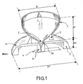
- a broadband antenna in accordance with the present invention comprises a first cup-shaped element 1 exhibiting a cup-like part proper extended by a stem 2.
- the cup-shaped element is made, preferably, by injection moulding, in particular under steam pressures, of a plastic in a mould exhibiting the profile of the cup.
- the plastic consists of any metallizable plastic that can easily be injection moulded, such as thermoplastic polymers of the polyethylene, polypropylene or similar type.
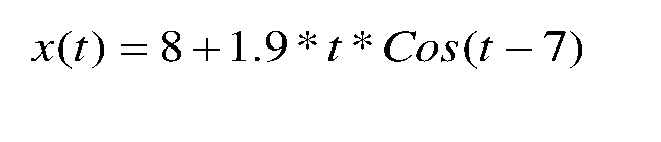
- the external profile of the cup-like element is, preferably, given by the following equations:
- the external surface of the cup-shaped element is coated with a metal such as tin-plated copper or chrome or some other known metallic material.
- the metallization of the plastic can be carried out using electrochemical processes or techniques such as vacuum spraying.
- copper is deposited chemically over a thickness of 3 ⁇ m and then a new electrochemical copper deposition is carried out over a thickness of around 10/20 ⁇ m, the whole being plated with bright tin using a chemical process.
- the antenna in accordance with the present invention also comprises an earth plane forming support 3.
- This support exhibits an annular shape and comprises a circular annulus 3a furnished at its centre with an aperture 3b for receiving the stem 2 of the cup-shaped element, this aperture being extended by a cylindrical part 3c allowing the mounting of the assembly on a substrate 4 described later.
- the external end of the annulus 3a is inwardly curved in such a way as to form a semi-toroidal element.
- the particular shape of the support element 3 gives, below the earth plane, a sufficient clearance to receive electronic circuits, such as a decoder, allowing the operation of the antenna.
- the earth plane forming support may likewise be obtained by injection moulding of a metallizable plastic as described hereinabove.
- the assembly consisting of the cup-shaped element and the earth plane forming support is mounted on a PCB-type substrate 4 by soldering the substrate 4 to the cylindrical element 3c of the earth plane and by soldering the stem of the cup-shaped element to an excitation line made on the substrate 4.
- wedges 5 are mounted between the external surface of the cup-shaped element 2 and the upper part 3a of the support 3.
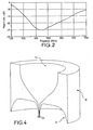
- an adaptation of less than -10 dB has been obtained over the whole of the UHF band, more particularly between 450 MHz and 1 000 MHz.
- an antenna of this type as represented diagrammatically in Figure 3D , the various radiation patterns represented in Figures 3A, 3B, 3C have been obtained, the radiation pattern represented in Figure 3A being that at 870 MHz, namely for the top frequency of the band, the pattern of Figure 3B being that at 666 MHz, namely for the central frequency of the operating band and the pattern of Figure 3C being that at 470 MHz, namely that of the bottom frequency of the operating band.
- the present invention makes it possible to obtain a very broadband antenna in the UHF band, namely the band used for TV reception, this antenna exhibiting a relatively restricted weight and bulkiness and being manufacturable at a modest cost. It can be used in particular for the reception of so-called "portable" televisions.
- cup-shaped element 11 and the earth plane forming support element 12 are made by machining a block 10 of metallizable foam such as the plastic foams supplied by the company Rohacell under the references 51 HF or 71 HF, or expanded polystyrene foams such as that sold by EMERSON and CUMING under the reference EP5.
- metallizable foam such as the plastic foams supplied by the company Rohacell under the references 51 HF or 71 HF, or expanded polystyrene foams such as that sold by EMERSON and CUMING under the reference EP5.
- the metallization of the structures may be carried out by applying a metalized paint such as AL351 from PROTAVIC by atomization.
- This relatively trim and compact structure enables the cup-shaped element and the earth plane forming support to be made from a single block of foam.
- the excitation line is soldered to the stem of the cup-shaped element by way of a metal insert.
Landscapes
- Details Of Aerials (AREA)
- Support Of Aerials (AREA)
Abstract
Claims (7)
- Antenne monopole large bande, comportant un élément rayonnant (1, 11') monté sur un support formant plan de masse (3,12) de forme annulaire, caractérisée en ce que l'élément rayonnant est constitué par un élément creux en forme de « calice » solidaire du support formant plan de masse, ledit élément rayonnant et ledit support étant réalisés à base d' une matière plastique ou d'une mousse métallisables, le profil externe de l'élément rayonnant en forme de « calice » étant donné par les équations suivantes :Pour 1.3<t<4.075


- Antenne selon la revendication 1, caractérisée en ce que le support (3) formant plan de masse de forme annulaire est constitué d'un anneau circulaire (3a).
- Antenne selon la revendication 2, caractérisée en ce que l'extrémité externe de l'anneau est incurvée de manière à former un élément semi-torique.
- Procédé de fabrication d'une antenne monopole large bande comprenant un élément rayonnant monté sur un support formant plan de masse de forme annulaire, l'élément rayonnant étant constitué d'un élément creux en forme de « calice », le profil externe de l'élément rayonnant en forme de « calice » étant donné par les équations suivantes :Pour 1.3<t<4.075

 caractérisé en ce l'élément rayonnant en forme de « calice » et le support formant plan de masse sont réalisés par moulage par injection d'une matière plastique suivie par la métallisation d'au moins la surface extérieure de l'élément en forme de « calice » et de la partie formant plan de masse.
 - Procédé selon la revendication 4, caractérisé en ce que la métallisation est obtenue par pulvérisation sous vide du métal ou par un procédé électrochimique.
- Procédé de fabrication d'une antenne monopole large bande comprenant un élément rayonnant monté sur un support formant plan de masse de forme annulaire, l'élément rayonnant étant constitué d'un élément creux en forme de « calice », le profil externe de l'élément rayonnant en forme de « calice » étant donné par les équations suivantes :Pour 1.3<t<4.075

caractérisé en ce que l'élément rayonnant en forme de « calice » et le support formant plan de masse sont réalisés par usinage d'un seul bloc de mousse plastique suivi par la métallisation d'au moins la surface extérieure de l'élément en forme de « calice » et de la partie formant plan de masse. - Procédé selon la revendication 6, caractérisé en ce que la métallisation est obtenue par vaporisation d'une peinture électriquement conductrice.
Applications Claiming Priority (3)
| Application Number | Priority Date | Filing Date | Title |
|---|---|---|---|
| FR0209640A FR2843237B1 (fr) | 2002-07-30 | 2002-07-30 | Antenne large bande et procedes de fabrication d'une telle antenne |
| FR0209640 | 2002-07-30 | ||
| PCT/EP2003/050325 WO2004013932A1 (fr) | 2002-07-30 | 2003-07-21 | Antenne a large bande et procedes de fabrication de celle-ci |
Publications (2)
| Publication Number | Publication Date |
|---|---|
| EP1525643A1 EP1525643A1 (fr) | 2005-04-27 |
| EP1525643B1 true EP1525643B1 (fr) | 2012-03-14 |
Family
ID=30129521
Family Applications (1)
| Application Number | Title | Priority Date | Filing Date |
|---|---|---|---|
| EP03766405A Expired - Lifetime EP1525643B1 (fr) | 2002-07-30 | 2003-07-21 | Antenne a large bande et procedes de fabrication de celle-ci |
Country Status (5)
| Country | Link |
|---|---|
| US (1) | US7479929B2 (fr) |
| EP (1) | EP1525643B1 (fr) |
| AU (1) | AU2003262532A1 (fr) |
| FR (1) | FR2843237B1 (fr) |
| WO (1) | WO2004013932A1 (fr) |
Families Citing this family (7)
| Publication number | Priority date | Publication date | Assignee | Title |
|---|---|---|---|---|
| FR2883671A1 (fr) | 2005-03-24 | 2006-09-29 | Groupe Ecoles Telecomm | Antenne ultra-large bande offrant une grande flexibilite de conception |
| JP2010522498A (ja) * | 2007-03-23 | 2010-07-01 | クゥアルコム・インコーポレイテッド | 実質的に同じ特性を有する第1および第2の放射素子を含むアンテナ |
| US8736506B1 (en) * | 2011-04-05 | 2014-05-27 | The United States Of America As Represented By The Secretary Of The Navy | Wideband aircraft antenna with extended frequency range |
| KR102048997B1 (ko) * | 2019-01-17 | 2019-11-27 | 국방과학연구소 | 미앤더 단락 핀을 이용한 uhf 광대역 모노콘 안테나 |
| US11888246B2 (en) * | 2021-11-01 | 2024-01-30 | Src, Inc. | Wideband monopole antenna |
| CN114188717A (zh) * | 2021-12-16 | 2022-03-15 | 陕西海积信息科技有限公司 | 机载天线以及飞机 |
| CN119111015A (zh) * | 2022-04-29 | 2024-12-10 | 京瓷Avx元器件(圣地亚哥)有限公司 | 超宽带天线组件 |
Family Cites Families (6)
| Publication number | Priority date | Publication date | Assignee | Title |
|---|---|---|---|---|
| NL62581C (fr) * | 1938-05-18 | |||
| US2454766A (en) * | 1943-04-24 | 1948-11-30 | Standard Telephones Cables Ltd | Broad band antenna |
| GB2105914B (en) * | 1981-08-27 | 1985-02-27 | Marconi Co Ltd | Electromagnetic horns |
| US4788554A (en) * | 1985-03-28 | 1988-11-29 | Satellite Technology Services, Inc. | Plated plastic injection molded horn for antenna |
| IT1319430B1 (it) * | 2000-09-13 | 2003-10-10 | Zendar Spa | Antenna a basso profilo, senza stilo |
| US7057572B2 (en) * | 2002-11-02 | 2006-06-06 | Electronics And Telecommunications Research Institute | Horn antenna system having a strip line feeding structure |
-
2002
- 2002-07-30 FR FR0209640A patent/FR2843237B1/fr not_active Expired - Fee Related
-
2003
- 2003-07-21 AU AU2003262532A patent/AU2003262532A1/en not_active Abandoned
- 2003-07-21 EP EP03766405A patent/EP1525643B1/fr not_active Expired - Lifetime
- 2003-07-21 WO PCT/EP2003/050325 patent/WO2004013932A1/fr not_active Ceased
- 2003-07-21 US US10/523,182 patent/US7479929B2/en not_active Expired - Fee Related
Also Published As
| Publication number | Publication date |
|---|---|
| WO2004013932A1 (fr) | 2004-02-12 |
| FR2843237B1 (fr) | 2008-07-04 |
| US7479929B2 (en) | 2009-01-20 |
| AU2003262532A1 (en) | 2004-02-23 |
| EP1525643A1 (fr) | 2005-04-27 |
| FR2843237A1 (fr) | 2004-02-06 |
| US20070146224A1 (en) | 2007-06-28 |
Similar Documents
| Publication | Publication Date | Title |
|---|---|---|
| US6646618B2 (en) | Low-profile slot antenna for vehicular communications and methods of making and designing same | |
| US7551145B2 (en) | Slot antenna | |
| US7339542B2 (en) | Ultra-broadband antenna system combining an asymmetrical dipole and a biconical dipole to form a monopole | |
| EP0883908B1 (fr) | Combinaison satellite et antenne de reception vhf/uhf | |
| KR100756785B1 (ko) | 개별형 용량성 커플링을 갖는 위상 배열 안테나 및 그 제조 방법 | |
| CN100490248C (zh) | 天线装置 | |
| US6563468B2 (en) | Omni directional antenna with multiple polarizations | |
| US5977931A (en) | Low visibility radio antenna with dual polarization | |
| US6975277B2 (en) | Wireless communications device pseudo-fractal antenna | |
| US6750825B1 (en) | Monopole wire-plate antenna | |
| WO2001047063A1 (fr) | Antenne accordable a polarisation circulaire et profil bas | |
| US20070262915A1 (en) | Antenna device | |
| EP2666207B1 (fr) | Dispositif de communication et dispositif de poursuite avec antenne à fente et procédé correspondent | |
| US6911952B2 (en) | Crossed-slot antenna for mobile satellite and terrestrial radio reception | |
| US6778149B2 (en) | Composite antenna apparatus | |
| JP5122276B2 (ja) | 接地平面および/または少なくとも1つの放射素子から延びる導電性スタッドを有する平面アンテナとその製造方法 | |
| EP1525643B1 (fr) | Antenne a large bande et procedes de fabrication de celle-ci | |
| US20080316138A1 (en) | Balance-fed helical antenna | |
| US20050264462A1 (en) | Antenna device | |
| EP1330852B1 (fr) | Antenne equidirective a polarisation multiple | |
| KR20130055380A (ko) | 샤크핀 통합형 안테나 | |
| JP2011066865A (ja) | 平面型アンテナ | |
| JP2003087031A (ja) | アンテナ | |
| JPH09162629A (ja) | マイクロストリップアンテナ | |
| JPH09162635A (ja) | マイクロストリップアンテナ |
Legal Events
| Date | Code | Title | Description |
|---|---|---|---|
| PUAI | Public reference made under article 153(3) epc to a published international application that has entered the european phase |
Free format text: ORIGINAL CODE: 0009012 |
|
| 17P | Request for examination filed |
Effective date: 20050214 |
|
| AK | Designated contracting states |
Kind code of ref document: A1 Designated state(s): AT BE BG CH CY CZ DE DK EE ES FI FR GB GR HU IE IT LI LU MC NL PT RO SE SI SK TR |
|
| AX | Request for extension of the european patent |
Extension state: AL LT LV MK |
|
| RAP1 | Party data changed (applicant data changed or rights of an application transferred) |
Owner name: THOMSON LICENSING |
|
| DAX | Request for extension of the european patent (deleted) | ||
| RBV | Designated contracting states (corrected) |
Designated state(s): DE FR GB IT |
|
| 17Q | First examination report despatched |
Effective date: 20070322 |
|
| RAP1 | Party data changed (applicant data changed or rights of an application transferred) |
Owner name: THOMSON LICENSING |
|
| GRAP | Despatch of communication of intention to grant a patent |
Free format text: ORIGINAL CODE: EPIDOSNIGR1 |
|
| GRAS | Grant fee paid |
Free format text: ORIGINAL CODE: EPIDOSNIGR3 |
|
| GRAA | (expected) grant |
Free format text: ORIGINAL CODE: 0009210 |
|
| AK | Designated contracting states |
Kind code of ref document: B1 Designated state(s): DE FR GB IT |
|
| REG | Reference to a national code |
Ref country code: GB Ref legal event code: FG4D |
|
| REG | Reference to a national code |
Ref country code: GB Ref legal event code: 746 Effective date: 20120322 |
|
| REG | Reference to a national code |
Ref country code: DE Ref legal event code: R096 Ref document number: 60340286 Country of ref document: DE Effective date: 20120510 |
|
| PLBE | No opposition filed within time limit |
Free format text: ORIGINAL CODE: 0009261 |
|
| STAA | Information on the status of an ep patent application or granted ep patent |
Free format text: STATUS: NO OPPOSITION FILED WITHIN TIME LIMIT |
|
| 26N | No opposition filed |
Effective date: 20121217 |
|
| PG25 | Lapsed in a contracting state [announced via postgrant information from national office to epo] |
Ref country code: IT Free format text: LAPSE BECAUSE OF FAILURE TO SUBMIT A TRANSLATION OF THE DESCRIPTION OR TO PAY THE FEE WITHIN THE PRESCRIBED TIME-LIMIT Effective date: 20120314 |
|
| REG | Reference to a national code |
Ref country code: DE Ref legal event code: R097 Ref document number: 60340286 Country of ref document: DE Effective date: 20121217 |
|
| REG | Reference to a national code |
Ref country code: FR Ref legal event code: PLFP Year of fee payment: 14 |
|
| REG | Reference to a national code |
Ref country code: FR Ref legal event code: PLFP Year of fee payment: 15 |
|
| REG | Reference to a national code |
Ref country code: DE Ref legal event code: R082 Ref document number: 60340286 Country of ref document: DE Representative=s name: DEHNS, DE Ref country code: DE Ref legal event code: R082 Ref document number: 60340286 Country of ref document: DE Representative=s name: HOFSTETTER, SCHURACK & PARTNER PATENT- UND REC, DE |
|
| REG | Reference to a national code |
Ref country code: FR Ref legal event code: PLFP Year of fee payment: 16 |
|
| REG | Reference to a national code |
Ref country code: FR Ref legal event code: TP Owner name: THOMSON LICENSING DTV, FR Effective date: 20180830 |
|
| REG | Reference to a national code |
Ref country code: GB Ref legal event code: 732E Free format text: REGISTERED BETWEEN 20180927 AND 20181005 |
|
| REG | Reference to a national code |
Ref country code: DE Ref legal event code: R082 Ref document number: 60340286 Country of ref document: DE Representative=s name: DEHNS, DE Ref country code: DE Ref legal event code: R081 Ref document number: 60340286 Country of ref document: DE Owner name: INTERDIGITAL MADISON PATENT HOLDINGS, FR Free format text: FORMER OWNER: THOMSON LICENSING, ISSY-LES-MOULINEAUX, FR |
|
| PGFP | Annual fee paid to national office [announced via postgrant information from national office to epo] |
Ref country code: FR Payment date: 20190725 Year of fee payment: 17 |
|
| PGFP | Annual fee paid to national office [announced via postgrant information from national office to epo] |
Ref country code: GB Payment date: 20190729 Year of fee payment: 17 |
|
| PGFP | Annual fee paid to national office [announced via postgrant information from national office to epo] |
Ref country code: DE Payment date: 20190930 Year of fee payment: 17 |
|
| REG | Reference to a national code |
Ref country code: DE Ref legal event code: R119 Ref document number: 60340286 Country of ref document: DE |
|
| GBPC | Gb: european patent ceased through non-payment of renewal fee |
Effective date: 20200721 |
|
| PG25 | Lapsed in a contracting state [announced via postgrant information from national office to epo] |
Ref country code: FR Free format text: LAPSE BECAUSE OF NON-PAYMENT OF DUE FEES Effective date: 20200731 Ref country code: GB Free format text: LAPSE BECAUSE OF NON-PAYMENT OF DUE FEES Effective date: 20200721 |
|
| PG25 | Lapsed in a contracting state [announced via postgrant information from national office to epo] |
Ref country code: DE Free format text: LAPSE BECAUSE OF NON-PAYMENT OF DUE FEES Effective date: 20210202 |