EP1524489A1 - Dispositif d'amorcage et charge formée multi modes mettant en oeuvre un tel dispositif d'amorcage - Google Patents
Dispositif d'amorcage et charge formée multi modes mettant en oeuvre un tel dispositif d'amorcage Download PDFInfo
- Publication number
- EP1524489A1 EP1524489A1 EP04292291A EP04292291A EP1524489A1 EP 1524489 A1 EP1524489 A1 EP 1524489A1 EP 04292291 A EP04292291 A EP 04292291A EP 04292291 A EP04292291 A EP 04292291A EP 1524489 A1 EP1524489 A1 EP 1524489A1
- Authority
- EP
- European Patent Office
- Prior art keywords
- relays
- relay
- plate
- detonation
- sheet
- Prior art date
- Legal status (The legal status is an assumption and is not a legal conclusion. Google has not performed a legal analysis and makes no representation as to the accuracy of the status listed.)
- Granted
Links
Images




Classifications
-
- F—MECHANICAL ENGINEERING; LIGHTING; HEATING; WEAPONS; BLASTING
- F42—AMMUNITION; BLASTING
- F42C—AMMUNITION FUZES; ARMING OR SAFETY MEANS THEREFOR
- F42C19/00—Details of fuzes
- F42C19/08—Primers; Detonators
- F42C19/0838—Primers or igniters for the initiation or the explosive charge in a warhead
- F42C19/0842—Arrangements of a multiplicity of primers or detonators, dispersed within a warhead, for multiple mode selection
-
- F—MECHANICAL ENGINEERING; LIGHTING; HEATING; WEAPONS; BLASTING
- F42—AMMUNITION; BLASTING
- F42C—AMMUNITION FUZES; ARMING OR SAFETY MEANS THEREFOR
- F42C19/00—Details of fuzes
- F42C19/08—Primers; Detonators
- F42C19/095—Arrangements of a multiplicity of primers or detonators, dispersed around a warhead, one of the primers or detonators being selected for directional detonation effects
Definitions
- the technical field of the invention is that of devices for priming an explosive charge and in particular that of devices for priming a load formed multi modes.
- Priming devices are known in which a detonator is attached to a movable plate allowing align it with a detonation relay itself initiating a explosive charge.
- the detonator can thus occupy a misaligned position (in which he does not can initiate the explosive charge) and an aligned position in which initiation is possible.
- the detonator is most often controlled by a rocket boot to which it is connected by a wired connection.
- All detonators are connected to a means of initiation through separate wire connections.
- the priming device allows, playing on the position of a control board, to ensure or not the initiation of an explosive charge.
- it implements only one fixed detonator which simplifies the electrical connections.
- the device according to the invention also makes it possible Reliable and simple way, to ensure various types of priming multipoint from a single detonator.
- the subject of the invention is a priming device having a detonator and at least one detonation relay, characterized in that it comprises, arranged between the detonator and the detonation relay (s) on the one hand at least one transmission explosive sheet comprising at least minus one hole, and secondly at least one movable stage carrying at least one intermediate diameter relay less than that of the hole, the explosive relay sheet being disposed so as to be initiated by the detonator, the mobile stage which can occupy at least two positions, a first position or inactivated position in which the intermediate relay is arranged opposite the hole and a second position or priming position in which the intermediate relay is located between the explosive sheet of transmission and a detonation relay.
- the mobile stage is a rotating turntable carrying at least three intermediate relays regularly angularly distributed and intended to be positioned either in view of holes carried by the transmission sheet either in detonation relay look.
- the mobile stage may comprise a intermediate relay ring arranged in the vicinity of its external periphery, so-called peripheral relays.
- the mobile stage can also have at least three other intermediate relays (or median relays) arranged at a substantially circle median of the platinum, the device comprising moreover a second sheet of transmission explosive arranged between the median relays of the turntable and a relay of axial detonation, the median relays can also be positioned next to holes carried by the first sheet of explosive transmission.
- intermediate relays or median relays
- the median relays of the stage can be arranged at the level of a circle whose diameter will be appreciably half of the diameter of the circle at which will be arranged the peripheral relays of the board.
- the movable stage may be movable by a means motor actuated by a control means.
- the motor means may comprise a screw or a pinion meshing on a toothed portion of the plate.
- the subject of the invention is also a shaped charge multi modes incorporating such a priming device.
- the multi-mode shaped charge according to the invention comprises a coating and an explosive charge interposed between the coating and the priming device, this charge characterized in that it can be initiated according to at least two different modes: either by a detonation relay axial or by a detonation relay crown the choice of one or the other of the modes of operation being obtained by the control of the pivoting a priming device board carrying relays intermediate.
- the multi-mode shaped charge can be initiated according to at least three different modes: axial detonation relay, by a relay ring of external detonation, or by the simultaneous initiation of the relay axial and external detonation relay crown, the choice of the operating mode being obtained by the command pivoting the platen.
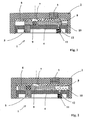
- a device 1 according to a first embodiment of the invention comprises a housing 2 whose upper face carries a detonator 3 which is connected by non represented at a firing device (not shown).
- the housing 2 is closed by a cover 4 which carries a detonation relay 5.
- the latter is arranged opposite a explosive charge (not shown) that it is loaded initiate.
- the device 1 comprises a 6 explosive transmission sheet which is arranged at the bottom housing 2 opposite the detonator 3.
- This sheet is made for example in an explosive Rubber and pentrite-based plastic (known explosive under the brand Formex) and it has a hole 7. It is fixed to the housing 2 for example by gluing.
- the device according to the invention also comprises a mobile turntable 8 which carries a pyrotechnic relay intermediate 9 whose diameter is chosen less than that 7.
- This relay may consist of a tablet of hexowax.
- the plate 8 can be moved by the action of a means motor which is here a compression spring 10 disposed between a rim of the plate 8 and an inner surface of the housing 2. In the position shown in Figure 1, this spring is kept compressed thanks to a latch 11 carried by the lid 4.
- the rod 12 of this lock enters a housing of the platen 8 and immobilizes it with respect to the cover 4.
- the lock 11 may be constituted by a small electro magnet.
- the firing of the detonator 3 leads to the initiation of the explosive sheet 6. Due to the presence of the hole 7 opposite intermediate relay 9 the latter is not initiated.
- the detonation relay 5 is also opposite the platinum 8 which plays the role of screen. So he is not he more initiated.
- the plate 8 find released. It is pushed by spring 10 and takes the priming position shown in Figure 2 (position in which the platen can be blocked by means of blocking not shown).
- the intermediate relay 9 is located positioned between the transmission explosive sheet 6 and the detonation relay 5.
- the firing of the detonator 3 then leads to the initiation of the transmission explosive sheet 6 which initiates the intermediate relay 9. The latter then initiates the detonation relay 5 which causes the firing of the explosive charge (not shown).
- This device thus makes it possible to obtain in a simple manner activating or deactivating a boot.
- this sheet propagates in every point of its lower face a wave of detonation communicated to him by the detonator primer positioned at its upper face.
- One or more holes on this sheet will define areas at level of which there will be no wave transmission of detonation.
- the device according to the invention is more particularly interesting to perform multi-point priming for multimode shaped charges.
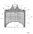
- FIG. 3 thus shows a formed charge 13 which conventionally comprises an explosive charge 15 disposed in an envelope 16.
- a concave coating 14 is applied to the explosive charge 15.
- a priming device 1 according to a second mode of embodiment of the invention is attached to the envelope 16 by means not shown.
- This charge can be initiated according to at least two different modes. It can be initiated by a relay of axial detonation 17 or else by a relay crown of external detonation 18.
- the relays 19 of the outer ring and the axial relay 17 the interactions between the different shock waves cause a dislocation of the coating in the form of chips.
- the concavity of the coating is defined by the man of the Occupation to enable load operation following several modes. This geometry is not the subject of the present invention and therefore it is useless to specify more. We can refer to the patent EP1164348 which describes a possible type of coating.
- the priming device according to the invention allows to easily obtain one or other of the modes of functioning from the initiation of a single primer detonator 3.
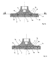
- Figures 4a, 4b and 4c show in a more specifies the structure of this device 1.
- the cover 4 which closes the housing 2 carries a relay of 17 axial detonation and a detonation relay crown 18. These relays are in contact with the load explosive 15 of the formed charge 13 (see FIG. 3).
- a sheet of explosive transmission 6a is disposed at the bottom of the housing 2 next to detonator 3. This sheet is glued to housing 2.
- the detonator 3 is connected to a setting device fire not shown.
- the lid 4 carries a circular bowl inside which is placed a second sheet 6b of explosive transmission, sheet having the same composition as the first sheet 6a and which is glued to the lid 4.
- the diameter of this second sheet 6b is substantially equal to half the diameter of the first sheet 6a.
- the plate 8 is circular and in support against an inner circular shoulder 21 of the housing 2. This provision is intended to prevent friction between the plate 8 and the relay sheet 6a during the pivoting of the platinum.
- This turntable 8 carries a relay crown intermediate 9a regularly distributed angularly (here twenty four relays) arranged in the vicinity of its periphery external.
- peripherals These relays will be called peripherals and they are intended to be positioned either facing peripheral holes 7a carried by the first transmission sheet 6a, either in look at external detonation relays 18.
- platinum swivel 8 also carries four other relays intermediates 9b (called median relays) which are arranged at level of a substantially median circle of the plate 8.
- median relays 9b are arranged opposite the second sheet of transmission explosive 6b. Following the angular positioning of the plate 8, they can be positioned or not facing holes 7b carried by the first transmission relay sheet 6a.
- the first sheet of transmission explosive 6a carries so twenty four peripheral holes 7a and four holes medians 7b angularly arranged at 90 ° from each other.
- the median holes 7b are located angularly on diameters that also pass through peripheral holes 7a.
- the transmission explosive sheet 6a is partially cut on its left side (cutting line L) so as to show the plate 8, some relays 9a peripherals and a median relay 9b.
- the relays 9a and 9b of the plate 8 are shown in black when are visible in the figure and in gray when they are hidden by the explosive sheet 6a.
- the turntable 8 thus carries twenty four relays 9a peripherals and four median relays 9b.
- the relays medians 9b lie angularly on diameters which are offset relative to the diameters carrying the relays 9a devices.
- a median relay 9b is on a diameter D3 which is bisector of diameters D1 and D2 passing through two relays consecutive devices 9a.
- FIGS. 4a, 4b and 4c represent the device in a first position in which the detonator 3 command only the initiation of detonation relays external 18.
- the first sheet of transmission explosive 6a does not initiate median relays 9b of the plate 8, the latter being positioned in look at the median holes 7b worn by the first leaf 6a.
- the second sheet 6b of transmission explosive is therefore not initiated and the relay detonation axial 17 no more.
- FIGS. 5a, 5b and 5c show the device according to the invention in its second position.
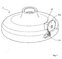
- the plate 8 was rotated by 7.5 ° by the action of the motor on the screw 19 thus on the toothed portion 20 of the plate 8.
- peripheral relays 9a of the platinum 8 are all positioned next to the holes 7a devices carried by the first sheet 6a.
- the latter can not initiate the relays 9a devices.
- the firing of the detonator 3 then leads to initiation of the axial detonation relay 17 alone by through the median relays 9b of the platinum as well as by the two sheets of transmission explosive 6a and 6b.
- the explosive charge 15 of the formed charge 13 is then initiated axially. This initiation leads to kernel formation.
- FIGS. 6a, 6b, 6c and 6d show the device according to the invention in its third position.
- detonator 3 therefore leads to initiation of all twenty four external detonation relays 18 as well as that of the axial detonation relay 17.
- the median relays 9b of the plate 8 are arranged at a circle whose diameter is substantially half the diameter of the circle at at which level the peripheral relays 9a are arranged.
- the time required for the detonation wave to reach to the peripheral relays 9a is therefore almost equal to the sum of the time required for this wave to reach the median relays 9b and the time required for the wave of detonation to traverse the second sheet radially of explosive transmission 6b (the explosives used to the two leaves being the same).
- the skilled person may settle the possible delay desired between the initiation of the peripheral relays 18 and that of the axial relay 17 by varying the diameter of the circle of the plate 8 carrying the median relays 9b with respect to the diameter of the circle carrying the peripheral relays 9a. he will also play on the detonation features of each sheet of transmission explosive 6a, 6b.
- the platinum would carry a number of different relay, both in the periphery and in the middle zone.
- the motor means for rotating the turntable could be of different structure. We could also use a piezoelectric actuator to advance the platinum a desired angle via a snap.
Landscapes
- Engineering & Computer Science (AREA)
- General Engineering & Computer Science (AREA)
- Portable Nailing Machines And Staplers (AREA)
- Pressure Welding/Diffusion-Bonding (AREA)
- Ignition Installations For Internal Combustion Engines (AREA)
- Materials For Medical Uses (AREA)
- Coating Apparatus (AREA)
- Dowels (AREA)
- Perforating, Stamping-Out Or Severing By Means Other Than Cutting (AREA)
Abstract
Description
- une première position dans laquelle le détonateur est relié uniquement à des relais de détonation externes par l'intermédiaire de la première feuille d'explosif de transmission ainsi que par les relais périphériques de la platine, les relais médians de la platine étant alors positionnés en regard de trous médians portés par la première feuille,
- une deuxième position dans laquelle le détonateur est relié uniquement au relais de détonation axial par l'intermédiaire des relais médians de la platine ainsi que par les deux feuilles d'explosif de transmission, les relais périphériques de la platine étant alors positionnés en regard de trous périphériques portés par la première feuille,
- une troisième position dans laquelle le détonateur est relié à la fois au relais de détonation axial et aux relais de détonation externes par l'intermédiaire des relais de la platine et des deux feuilles d'explosif de transmission.
- la figure 1 représente un dispositif d'amorçage suivant un premier mode de réalisation de l'invention, dispositif représentée en position inactivée,
- la figure 2 représente ce même dispositif d'amorçage dans sa position d'amorçage,
- la figure 3 est une vue en coupe longitudinale d'une charge formée équipée d'un dispositif d'amorçage suivant un deuxième mode de réalisation,
- la figure 4a représente en coupe le dispositif d'amorçage de cette charge, seul et dans sa première position, le dispositif est coupé suivant le plan dont la trace BB est repérée à la figure 4b,
- la figure 4b représente, avec une découpe partielle de la feuille d'explosif de transmission, le dispositif dans sa première position et coupé suivant le plan dont la trace AA est repérée à la figure 4a,
- la figure 4c est une autre vue en coupe du dispositif d'amorçage coupé suivant le plan dont la trace XX est repérée à la figure 4b,
- la figure 5a représente en coupe le dispositif d'amorçage de cette charge, seul et dans sa deuxième position, le dispositif est coupé suivant le plan dont la trace DD est repérée à la figure 5b,
- la figure 5b représente, avec une découpe partielle de la feuille d'explosif de transmission, le dispositif dans sa deuxième position et coupé suivant le plan dont la trace CC est repérée à la figure 5a,
- la figure 5c est une autre vue en coupe du dispositif d'amorçage coupé suivant le plan dont la trace YY est repérée à la figure 5b,
- la figure 6a représente en coupe le dispositif d'amorçage de cette charge, seul et dans sa deuxième position, le dispositif est coupé suivant le plan dont la trace FF est repérée à la figure 6b,
- la figure 6b représente, avec une découpe partielle de la feuille d'explosif de transmission, le dispositif dans sa deuxième position et coupé suivant le plan dont la trace EE est repérée à la figure 6a,
- les figures 6c et 6d sont deux autres vues en coupe du dispositif d'amorçage coupé suivant les plans dont les traces sont repérées respectivement ZZ et WW sur la figure 6b,
- la figure 7 est une vue en perspective externe du dispositif d'amorçage suivant le deuxième mode de réalisation de l'invention, vue permettant de visualiser un exemple de mise en place d'un moteur de commande du pivotement de la platine.
Claims (10)
- Dispositif d'amorçage (1) comportant un détonateur (3) et au moins un relais de détonation (5), dispositif caractérisé en ce qu'il comprend, disposées entre le détonateur (3) et le ou les relais de détonation (5), d'une part au moins une feuille d'explosif de transmission (6,6a) comportant au moins un trou (7,7a,7b), et d'autre part au moins une platine mobile (8) portant au moins un relais intermédiaire (9,9a,9b) de diamètre inférieur à celui du trou (7,7a,7b), la feuille d'explosif relais (6,6a) étant disposée de façon à être initiée par le détonateur (3), la platine mobile (8) pouvant occuper au moins deux positions, une première position ou position inactivée dans laquelle le relais intermédiaire (9,9a,9b) est disposé en regard du trou (7,7a,7b) et une deuxième position ou position d'amorçage dans laquelle le relais intermédiaire (9,9a,9b) se trouve entre la feuille d'explosif de transmission (6,6a) et un relais de détonation (5,17,18).
- Dispositif selon la revendication 1, caractérisé en ce que la platine mobile (8) est une platine circulaire pivotante portant au moins trois relais intermédiaires (9a) régulièrement répartis angulairement et destinés à être positionnés soit en regard de trous (7a) portés par la feuille de transmission (6a) soit en regard de relais de détonation (18).
- Dispositif selon la revendication 2, caractérisé en ce que la platine mobile (8) comporte une couronne de relais intermédiaires (9a) disposés au voisinage de sa périphérie externe, relais dits périphériques.
- Dispositif selon la revendication 3, caractérisé en ce que la platine mobile (8) comporte au moins trois autres relais intermédiaires (9b) (ou relais médians) disposés au niveau d'un cercle sensiblement médian de la platine (8), le dispositif comportant par ailleurs une deuxième feuille d'explosif de transmission (6b) disposée entre les relais médians (9b) de la platine et un relais de détonation axial (17), les relais médians (9b) pouvant également être positionnés en regard de trous (7b) portés par la première feuille d'explosif de transmission (6a).
- Dispositif selon la revendication 4, caractérisé en ce que les positions angulaires des trous périphériques (7a) et médians (7b) de la première feuille d'explosif de transmission (6a) ainsi que celles des relais périphériques (9a) et médians (9b) portés par la platine (8) sont choisies de telle sorte que la platine pivotante (8) peut occuper au moins trois positions angulaires différentes:une première position dans laquelle le détonateur (3) est relié uniquement à des relais de détonation externes (18) par l'intermédiaire de la première feuille d'explosif de transmission (6a) ainsi que par les relais périphériques (9a) de la platine (8), les relais médians (9b) de la platine étant alors positionnés en regard de trous médians (7b) portés par la première feuille (6a),une deuxième position dans laquelle le détonateur (3) est relié uniquement au relais de détonation axial (17) par l'intermédiaire des relais médians (9b) de la platine (8) ainsi que par les deux feuilles d'explosif de transmission (6a,6b), les relais périphériques (9a) de la platine (8) étant alors positionnés en regard de trous périphériques (7a) portés par la première feuille (6a),une troisième position dans laquelle le détonateur (3) est relié à la fois au relais de détonation axial (17) et aux relais de détonation externes (18) par l'intermédiaire des relais (9a,9b) de la platine (8) et des deux feuilles d'explosif de transmission (6a,6b).
- Dispositif selon une des revendications 4 ou 5, caractérisé en ce que les relais médians (9b) de la platine (8) sont disposés au niveau d'un cercle dont le diamètre est sensiblement la moitié du diamètre du cercle au niveau duquel sont disposés les relais périphériques (9a) de la platine (8) .
- Dispositif selon une des revendications 1 à 6, caractérisé en ce que la platine mobile (8) est déplaçable par un moyen moteur (19,22) actionné par un moyen de commande.
- Dispositif selon la revendication 7, caractérisé en ce que le moyen moteur comprend une vis (19) ou un pignon engrenant sur une portion dentée (20) de la platine (8).
- Charge formée multi mode (13) incorporant un dispositif d'amorçage (1) selon une des revendications 4 à 6 ainsi qu'un revêtement (14) et un chargement explosif (15) interposé entre le revêtement (14) et le dispositif d'amorçage (1), charge caractérisée en ce qu'elle peut être initiée suivant au moins deux modes différents : soit par un relais de détonation axial (17) ou soit par une couronne de relais de détonation externes (18), le choix de l'un ou de l'autre des modes de fonctionnement étant obtenu par la commande du pivotement d'une platine (8) du dispositif d'amorçage portant des relais intermédiaires (9a,9b).
- Charge formée multi mode selon la revendication 9, caractérisée en ce qu'elle peut être initiée suivant au moins trois modes différents : par un relais de détonation axial (17), par une couronne de relais de détonation externes (18), ou par l'initiation simultanée du relais axial (17) et de la couronne de relais de détonation externes (18), le choix du mode de fonctionnement étant obtenu par la commande du pivotement de la platine (8).
Applications Claiming Priority (2)
| Application Number | Priority Date | Filing Date | Title |
|---|---|---|---|
| FR0312203A FR2861168B1 (fr) | 2003-10-17 | 2003-10-17 | Dispositif d'amorcage et charge formee multi modes mettant en oeuvre un tel dispositif d'amorcage |
| FR0312203 | 2003-10-17 |
Publications (2)
| Publication Number | Publication Date |
|---|---|
| EP1524489A1 true EP1524489A1 (fr) | 2005-04-20 |
| EP1524489B1 EP1524489B1 (fr) | 2007-04-11 |
Family
ID=34355507
Family Applications (1)
| Application Number | Title | Priority Date | Filing Date |
|---|---|---|---|
| EP04292291A Expired - Lifetime EP1524489B1 (fr) | 2003-10-17 | 2004-09-23 | Dispositif d'amorcage et charge formée multi modes mettant en oeuvre un tel dispositif d'amorcage |
Country Status (4)
| Country | Link |
|---|---|
| EP (1) | EP1524489B1 (fr) |
| AT (1) | ATE359492T1 (fr) |
| DE (1) | DE602004005797T2 (fr) |
| FR (1) | FR2861168B1 (fr) |
Cited By (3)
| Publication number | Priority date | Publication date | Assignee | Title |
|---|---|---|---|---|
| FR2896577A1 (fr) * | 2006-01-24 | 2007-07-27 | Giat Ind Sa | Dispositif d'amorcage pour charge multi modes |
| EP1847797A2 (fr) | 2006-04-21 | 2007-10-24 | TDW Gesellschaft für verteidigungstechnische Wirksysteme mbH | Charge réglable |
| EP1967815A2 (fr) | 2007-03-06 | 2008-09-10 | TDW Gesellschaft für verteidigungstechnische Wirksysteme mbH | Chaîne d'allumage pour une charge d'action commutable |
Citations (5)
| Publication number | Priority date | Publication date | Assignee | Title |
|---|---|---|---|---|
| US3380385A (en) * | 1965-12-08 | 1968-04-30 | Magnavox Co | Energy-absorbing interruptor |
| US4784062A (en) * | 1986-07-31 | 1988-11-15 | Diehl Gmbh & Co. | Fuze for a projectile-forming charge |
| DE3728559C1 (en) * | 1987-08-27 | 1989-03-23 | Messerschmitt Boelkow Blohm | Shaped charge |
| US5939663A (en) * | 1996-02-14 | 1999-08-17 | The United States Of America As Represented By The Secretary Of The Army | Method for dispersing a jet from a shaped charge liner via multiple detonators |
| EP1164348A2 (fr) * | 2000-06-13 | 2001-12-19 | General Dynamics Ordnance and Tactical Systems, Inc. | Charge du type K pour tête de combat à fonction multiple du type charge creuse |
-
2003
- 2003-10-17 FR FR0312203A patent/FR2861168B1/fr not_active Expired - Fee Related
-
2004
- 2004-09-23 EP EP04292291A patent/EP1524489B1/fr not_active Expired - Lifetime
- 2004-09-23 AT AT04292291T patent/ATE359492T1/de not_active IP Right Cessation
- 2004-09-23 DE DE602004005797T patent/DE602004005797T2/de not_active Expired - Lifetime
Patent Citations (5)
| Publication number | Priority date | Publication date | Assignee | Title |
|---|---|---|---|---|
| US3380385A (en) * | 1965-12-08 | 1968-04-30 | Magnavox Co | Energy-absorbing interruptor |
| US4784062A (en) * | 1986-07-31 | 1988-11-15 | Diehl Gmbh & Co. | Fuze for a projectile-forming charge |
| DE3728559C1 (en) * | 1987-08-27 | 1989-03-23 | Messerschmitt Boelkow Blohm | Shaped charge |
| US5939663A (en) * | 1996-02-14 | 1999-08-17 | The United States Of America As Represented By The Secretary Of The Army | Method for dispersing a jet from a shaped charge liner via multiple detonators |
| EP1164348A2 (fr) * | 2000-06-13 | 2001-12-19 | General Dynamics Ordnance and Tactical Systems, Inc. | Charge du type K pour tête de combat à fonction multiple du type charge creuse |
Cited By (6)
| Publication number | Priority date | Publication date | Assignee | Title |
|---|---|---|---|---|
| FR2896577A1 (fr) * | 2006-01-24 | 2007-07-27 | Giat Ind Sa | Dispositif d'amorcage pour charge multi modes |
| EP1847797A2 (fr) | 2006-04-21 | 2007-10-24 | TDW Gesellschaft für verteidigungstechnische Wirksysteme mbH | Charge réglable |
| EP1847797A3 (fr) * | 2006-04-21 | 2010-02-24 | TDW Gesellschaft für verteidigungstechnische Wirksysteme mbH | Charge réglable |
| EP2312259A1 (fr) * | 2006-04-21 | 2011-04-20 | TDW Gesellschaft für verteidigungstechnische Wirksysteme mbH | Charge réglable |
| EP1967815A2 (fr) | 2007-03-06 | 2008-09-10 | TDW Gesellschaft für verteidigungstechnische Wirksysteme mbH | Chaîne d'allumage pour une charge d'action commutable |
| EP1967815A3 (fr) * | 2007-03-06 | 2009-12-16 | TDW Gesellschaft für verteidigungstechnische Wirksysteme mbH | Chaîne d'allumage pour une charge d'action commutable |
Also Published As
| Publication number | Publication date |
|---|---|
| EP1524489B1 (fr) | 2007-04-11 |
| DE602004005797T2 (de) | 2008-01-10 |
| DE602004005797D1 (de) | 2007-05-24 |
| FR2861168A1 (fr) | 2005-04-22 |
| FR2861168B1 (fr) | 2005-12-16 |
| ATE359492T1 (de) | 2007-05-15 |
Similar Documents
| Publication | Publication Date | Title |
|---|---|---|
| FR2717259A1 (fr) | Dispositif de guidage d'un missile. | |
| EP1247696A1 (fr) | Elément extérieur de véhicule automobile, intégrant un capteur capacitif et pièce de carrosserie comportant un tel élément extérieur | |
| EP1437260A1 (fr) | Rétroviseur pour véhicule comportant un miroir monté pivotant sur deux axes perpendiculaires | |
| EP1079200B9 (fr) | Dispositif pyrotechnique de connexion et de retard | |
| EP1524489B1 (fr) | Dispositif d'amorcage et charge formée multi modes mettant en oeuvre un tel dispositif d'amorcage | |
| WO2019129794A1 (fr) | Becquet de véhicule automobile comprenant une lame aérodynamique comprenant plusieurs ailettes | |
| BE902597A (nl) | Installation de soudage a mouvement orbital. | |
| EP0942257B1 (fr) | Mine, notamment antichar ou antivehicule, comportant des moyens de confirmation de la presence d'une cible | |
| EP0526315B1 (fr) | Contacteur électrique à commande pyrotechnique | |
| EP1672308B1 (fr) | Disposition d'initiation pour charge explosive ou composition pyrotechnique | |
| EP0536048A1 (fr) | Mine à défense de zone | |
| EP1577635B1 (fr) | Dispositif d'initiation de deux charges explosives et tête militaire mettant en oeuvre un tel dispositif d'initiation | |
| EP1499850B1 (fr) | Dispositif pyrotechnique de retard | |
| WO2016116691A1 (fr) | Dispositif de projection d'une garniture | |
| EP1366954A1 (fr) | Dispositif d'élairage et/ou de signalisation pour véhicule comprenant un masque | |
| FR2851022A1 (fr) | Dispositif de synchronisation pour boite de vitesses mecanique | |
| EP0016701A1 (fr) | Dispositif de sécurité pour chaîne pyrotechnique | |
| FR2896577A1 (fr) | Dispositif d'amorcage pour charge multi modes | |
| BE892195A (fr) | Perfectionnements aux dispositifs de detonation. | |
| FR2552871A1 (fr) | Projectile antichar agissant en vitesse defilante | |
| FR2519784A1 (fr) | Dispositif de transmission multivoies d'un ordre pyrotechnique comportant un ensemble relais a relevement de pieces | |
| FR2866701A1 (fr) | Charge formee generatrice de plusieurs noyaux | |
| FR2560983A1 (fr) | Systeme electrique pour l'initiation de charges pyrotechniques et munition ou fusee perfectionnee incorporant un tel systeme | |
| EP0489654B1 (fr) | Ensemble de commutation pour véhicules automobiles | |
| EP0098189B1 (fr) | Dispositif pyrotechnique à allumage manuel, en particulier pour la signalisation |
Legal Events
| Date | Code | Title | Description |
|---|---|---|---|
| PUAI | Public reference made under article 153(3) epc to a published international application that has entered the european phase |
Free format text: ORIGINAL CODE: 0009012 |
|
| AK | Designated contracting states |
Kind code of ref document: A1 Designated state(s): AT BE BG CH CY CZ DE DK EE ES FI FR GB GR HU IE IT LI LU MC NL PL PT RO SE SI SK TR |
|
| AX | Request for extension of the european patent |
Extension state: AL HR LT LV MK |
|
| 17P | Request for examination filed |
Effective date: 20051018 |
|
| AKX | Designation fees paid |
Designated state(s): AT BE BG CH CY CZ DE DK EE ES FI FR GB GR HU IE IT LI LU MC NL PL PT RO SE SI SK TR |
|
| GRAP | Despatch of communication of intention to grant a patent |
Free format text: ORIGINAL CODE: EPIDOSNIGR1 |
|
| GRAS | Grant fee paid |
Free format text: ORIGINAL CODE: EPIDOSNIGR3 |
|
| GRAA | (expected) grant |
Free format text: ORIGINAL CODE: 0009210 |
|
| AK | Designated contracting states |
Kind code of ref document: B1 Designated state(s): AT BE BG CH CY CZ DE DK EE ES FI FR GB GR HU IE IT LI LU MC NL PL PT RO SE SI SK TR |
|
| PG25 | Lapsed in a contracting state [announced via postgrant information from national office to epo] |
Ref country code: SI Free format text: LAPSE BECAUSE OF FAILURE TO SUBMIT A TRANSLATION OF THE DESCRIPTION OR TO PAY THE FEE WITHIN THE PRESCRIBED TIME-LIMIT Effective date: 20070411 Ref country code: FI Free format text: LAPSE BECAUSE OF FAILURE TO SUBMIT A TRANSLATION OF THE DESCRIPTION OR TO PAY THE FEE WITHIN THE PRESCRIBED TIME-LIMIT Effective date: 20070411 |
|
| REG | Reference to a national code |
Ref country code: GB Ref legal event code: FG4D Free format text: NOT ENGLISH |
|
| REG | Reference to a national code |
Ref country code: CH Ref legal event code: EP |
|
| REG | Reference to a national code |
Ref country code: IE Ref legal event code: FG4D Free format text: LANGUAGE OF EP DOCUMENT: FRENCH |
|
| GBT | Gb: translation of ep patent filed (gb section 77(6)(a)/1977) |
Effective date: 20070427 |
|
| REF | Corresponds to: |
Ref document number: 602004005797 Country of ref document: DE Date of ref document: 20070524 Kind code of ref document: P |
|
| REG | Reference to a national code |
Ref country code: SE Ref legal event code: TRGR |
|
| PG25 | Lapsed in a contracting state [announced via postgrant information from national office to epo] |
Ref country code: ES Free format text: LAPSE BECAUSE OF FAILURE TO SUBMIT A TRANSLATION OF THE DESCRIPTION OR TO PAY THE FEE WITHIN THE PRESCRIBED TIME-LIMIT Effective date: 20070722 |
|
| PG25 | Lapsed in a contracting state [announced via postgrant information from national office to epo] |
Ref country code: PT Free format text: LAPSE BECAUSE OF FAILURE TO SUBMIT A TRANSLATION OF THE DESCRIPTION OR TO PAY THE FEE WITHIN THE PRESCRIBED TIME-LIMIT Effective date: 20070911 |
|
| NLV1 | Nl: lapsed or annulled due to failure to fulfill the requirements of art. 29p and 29m of the patents act | ||
| REG | Reference to a national code |
Ref country code: CH Ref legal event code: NV Representative=s name: ING. MARCO ZARDI C/O M. ZARDI & CO. S.A. |
|
| PG25 | Lapsed in a contracting state [announced via postgrant information from national office to epo] |
Ref country code: AT Free format text: LAPSE BECAUSE OF FAILURE TO SUBMIT A TRANSLATION OF THE DESCRIPTION OR TO PAY THE FEE WITHIN THE PRESCRIBED TIME-LIMIT Effective date: 20070411 Ref country code: PL Free format text: LAPSE BECAUSE OF FAILURE TO SUBMIT A TRANSLATION OF THE DESCRIPTION OR TO PAY THE FEE WITHIN THE PRESCRIBED TIME-LIMIT Effective date: 20070411 |
|
| REG | Reference to a national code |
Ref country code: IE Ref legal event code: FD4D |
|
| PG25 | Lapsed in a contracting state [announced via postgrant information from national office to epo] |
Ref country code: DK Free format text: LAPSE BECAUSE OF FAILURE TO SUBMIT A TRANSLATION OF THE DESCRIPTION OR TO PAY THE FEE WITHIN THE PRESCRIBED TIME-LIMIT Effective date: 20070411 Ref country code: BG Free format text: LAPSE BECAUSE OF FAILURE TO SUBMIT A TRANSLATION OF THE DESCRIPTION OR TO PAY THE FEE WITHIN THE PRESCRIBED TIME-LIMIT Effective date: 20070711 Ref country code: IE Free format text: LAPSE BECAUSE OF FAILURE TO SUBMIT A TRANSLATION OF THE DESCRIPTION OR TO PAY THE FEE WITHIN THE PRESCRIBED TIME-LIMIT Effective date: 20070411 Ref country code: CZ Free format text: LAPSE BECAUSE OF FAILURE TO SUBMIT A TRANSLATION OF THE DESCRIPTION OR TO PAY THE FEE WITHIN THE PRESCRIBED TIME-LIMIT Effective date: 20070411 Ref country code: NL Free format text: LAPSE BECAUSE OF FAILURE TO SUBMIT A TRANSLATION OF THE DESCRIPTION OR TO PAY THE FEE WITHIN THE PRESCRIBED TIME-LIMIT Effective date: 20070411 |
|
| PLBE | No opposition filed within time limit |
Free format text: ORIGINAL CODE: 0009261 |
|
| STAA | Information on the status of an ep patent application or granted ep patent |
Free format text: STATUS: NO OPPOSITION FILED WITHIN TIME LIMIT |
|
| PG25 | Lapsed in a contracting state [announced via postgrant information from national office to epo] |
Ref country code: SK Free format text: LAPSE BECAUSE OF FAILURE TO SUBMIT A TRANSLATION OF THE DESCRIPTION OR TO PAY THE FEE WITHIN THE PRESCRIBED TIME-LIMIT Effective date: 20070411 |
|
| 26N | No opposition filed |
Effective date: 20080114 |
|
| BERE | Be: lapsed |
Owner name: NEXTER MUNITIONS Effective date: 20070930 |
|
| PG25 | Lapsed in a contracting state [announced via postgrant information from national office to epo] |
Ref country code: MC Free format text: LAPSE BECAUSE OF NON-PAYMENT OF DUE FEES Effective date: 20070930 Ref country code: GR Free format text: LAPSE BECAUSE OF FAILURE TO SUBMIT A TRANSLATION OF THE DESCRIPTION OR TO PAY THE FEE WITHIN THE PRESCRIBED TIME-LIMIT Effective date: 20070712 |
|
| PG25 | Lapsed in a contracting state [announced via postgrant information from national office to epo] |
Ref country code: RO Free format text: LAPSE BECAUSE OF FAILURE TO SUBMIT A TRANSLATION OF THE DESCRIPTION OR TO PAY THE FEE WITHIN THE PRESCRIBED TIME-LIMIT Effective date: 20070411 |
|
| PG25 | Lapsed in a contracting state [announced via postgrant information from national office to epo] |
Ref country code: BE Free format text: LAPSE BECAUSE OF NON-PAYMENT OF DUE FEES Effective date: 20070930 |
|
| PG25 | Lapsed in a contracting state [announced via postgrant information from national office to epo] |
Ref country code: EE Free format text: LAPSE BECAUSE OF FAILURE TO SUBMIT A TRANSLATION OF THE DESCRIPTION OR TO PAY THE FEE WITHIN THE PRESCRIBED TIME-LIMIT Effective date: 20070411 |
|
| PG25 | Lapsed in a contracting state [announced via postgrant information from national office to epo] |
Ref country code: CY Free format text: LAPSE BECAUSE OF FAILURE TO SUBMIT A TRANSLATION OF THE DESCRIPTION OR TO PAY THE FEE WITHIN THE PRESCRIBED TIME-LIMIT Effective date: 20070411 |
|
| PG25 | Lapsed in a contracting state [announced via postgrant information from national office to epo] |
Ref country code: LU Free format text: LAPSE BECAUSE OF NON-PAYMENT OF DUE FEES Effective date: 20070923 |
|
| PG25 | Lapsed in a contracting state [announced via postgrant information from national office to epo] |
Ref country code: HU Free format text: LAPSE BECAUSE OF FAILURE TO SUBMIT A TRANSLATION OF THE DESCRIPTION OR TO PAY THE FEE WITHIN THE PRESCRIBED TIME-LIMIT Effective date: 20071012 Ref country code: TR Free format text: LAPSE BECAUSE OF FAILURE TO SUBMIT A TRANSLATION OF THE DESCRIPTION OR TO PAY THE FEE WITHIN THE PRESCRIBED TIME-LIMIT Effective date: 20070411 |
|
| REG | Reference to a national code |
Ref country code: FR Ref legal event code: PLFP Year of fee payment: 13 |
|
| REG | Reference to a national code |
Ref country code: FR Ref legal event code: PLFP Year of fee payment: 14 |
|
| REG | Reference to a national code |
Ref country code: FR Ref legal event code: PLFP Year of fee payment: 15 |
|
| PGFP | Annual fee paid to national office [announced via postgrant information from national office to epo] |
Ref country code: IT Payment date: 20210824 Year of fee payment: 18 Ref country code: FR Payment date: 20210819 Year of fee payment: 18 |
|
| PGFP | Annual fee paid to national office [announced via postgrant information from national office to epo] |
Ref country code: SE Payment date: 20210819 Year of fee payment: 18 Ref country code: CH Payment date: 20210818 Year of fee payment: 18 Ref country code: DE Payment date: 20210818 Year of fee payment: 18 Ref country code: GB Payment date: 20210820 Year of fee payment: 18 |
|
| REG | Reference to a national code |
Ref country code: DE Ref legal event code: R119 Ref document number: 602004005797 Country of ref document: DE |
|
| REG | Reference to a national code |
Ref country code: CH Ref legal event code: PL |
|
| REG | Reference to a national code |
Ref country code: SE Ref legal event code: EUG |
|
| GBPC | Gb: european patent ceased through non-payment of renewal fee |
Effective date: 20220923 |
|
| PG25 | Lapsed in a contracting state [announced via postgrant information from national office to epo] |
Ref country code: LI Free format text: LAPSE BECAUSE OF NON-PAYMENT OF DUE FEES Effective date: 20220930 Ref country code: FR Free format text: LAPSE BECAUSE OF NON-PAYMENT OF DUE FEES Effective date: 20220930 Ref country code: DE Free format text: LAPSE BECAUSE OF NON-PAYMENT OF DUE FEES Effective date: 20230401 Ref country code: CH Free format text: LAPSE BECAUSE OF NON-PAYMENT OF DUE FEES Effective date: 20220930 |
|
| PG25 | Lapsed in a contracting state [announced via postgrant information from national office to epo] |
Ref country code: SE Free format text: LAPSE BECAUSE OF NON-PAYMENT OF DUE FEES Effective date: 20220924 |
|
| PG25 | Lapsed in a contracting state [announced via postgrant information from national office to epo] |
Ref country code: IT Free format text: LAPSE BECAUSE OF NON-PAYMENT OF DUE FEES Effective date: 20220923 Ref country code: GB Free format text: LAPSE BECAUSE OF NON-PAYMENT OF DUE FEES Effective date: 20220923 |