EP1524462B1 - Pressure balanced electromagnetic valve - Google Patents
Pressure balanced electromagnetic valve Download PDFInfo
- Publication number
- EP1524462B1 EP1524462B1 EP20040105085 EP04105085A EP1524462B1 EP 1524462 B1 EP1524462 B1 EP 1524462B1 EP 20040105085 EP20040105085 EP 20040105085 EP 04105085 A EP04105085 A EP 04105085A EP 1524462 B1 EP1524462 B1 EP 1524462B1
- Authority
- EP
- European Patent Office
- Prior art keywords
- armature
- pressure
- valve
- solenoid
- pressurizing
- Prior art date
- Legal status (The legal status is an assumption and is not a legal conclusion. Google has not performed a legal analysis and makes no representation as to the accuracy of the status listed.)
- Revoked
Links
Images

Classifications
-
- F—MECHANICAL ENGINEERING; LIGHTING; HEATING; WEAPONS; BLASTING
- F16—ENGINEERING ELEMENTS AND UNITS; GENERAL MEASURES FOR PRODUCING AND MAINTAINING EFFECTIVE FUNCTIONING OF MACHINES OR INSTALLATIONS; THERMAL INSULATION IN GENERAL
- F16K—VALVES; TAPS; COCKS; ACTUATING-FLOATS; DEVICES FOR VENTING OR AERATING
- F16K31/00—Actuating devices; Operating means; Releasing devices
- F16K31/02—Actuating devices; Operating means; Releasing devices electric; magnetic
- F16K31/06—Actuating devices; Operating means; Releasing devices electric; magnetic using a magnet, e.g. diaphragm valves, cutting off by means of a liquid
- F16K31/0686—Braking, pressure equilibration, shock absorbing
- F16K31/0693—Pressure equilibration of the armature
Definitions
- the invention relates to an electromagnet, in particular a switching or proportional solenoid for switching a pilot-operated pressure valve, comprising a housing for receiving and protecting the further solenoid components, at least one arranged in the housing, electrically acted coil for generating a magnetic field, at least one in the magnetic field arranged, linearly movable, designed as an actuator armature with LK: JS two axially opposing armature surfaces and a return device cooperating with the armature, wherein the armature is formed so that it closes or opens a valve seat of a pressure valve cooperating with the electromagnet.
- Such electromagnets are commonly used as a drive unit of valves.
- solenoids When used in valves, a distinction is generally made between solenoids and proportional solenoids.
- proportional solenoids are preferably used. That is why proportional solenoids are also used in pilot-operated pressure control valves.
- electromagnets are known for use in valves. These electromagnets comprise a housing, which surrounds at least one electrically pressurizable coil for generating a magnetic field, and an armature movably arranged in the magnetic field which is designed as an actuator with a valve seat sealing surface and at least one restoring device, which cooperates with the armature and against the Valve seat sealing surface acting force on the anchor brings.
- the return device must be designed so that in addition to be expended for the provision of the actuator without pressurization force required by the pressurization force from the return device must be applied.
- the spring is designed to be larger than would actually be necessary for the generation of a restoring force necessary for sealing.
- the spring thus requires more space, which in total either to larger electromagnets and thus to larger valves or to a suboptimal Exploitation of the space leads, whereby not the largest possible valve nominal width can be produced.
- the anchor is here constructed in several parts and acted upon pressure equalization on opposite anchor surfaces with feed pressure or working pressure.
- a working pressure anchor part is surrounded by a pre-pressure anchor part connected thereto.
- the pre-pressure anchor part is charged on both sides with admission pressure (feed pressure), whereas working pressure is applied to both end faces of the working pressure anchor part. This is achieved by respectively associated through holes.
- the passage opening of the working Schuckankerteils extends coaxially through this, whereas the pre-pressure anchor part has an off-center longitudinal bore as a through hole.
- the anchor parts are provided with a plurality of bores to perform the functions described above.
- the invention includes the technical teaching that the armature has means for pressure equalization at valve seat side pressure-loaded first anchor surface, so that the LK: hv
- Return device cooperates with a compensation force on a second, the first armature surface opposing armature surface, whereby the return device is interpretable only in accordance with the applied sealing force for the valve seat.
- This solution offers the advantage that an equilibrium pressure applied from one side of the armature is additionally acted upon by an opposing counterpressure, whereby the two pressures act correspondingly opposite and thus a pressure compensation is created by the pressure acting alone the force of the reset device.
- This reset device can thus optimally interpret the corresponding requirements and accordingly can also be the space for the return device, so that the electromagnet and finally the valve or the corresponding device with which the solenoid cooperates design.
- an armature in the electromagnet is cylindrically formed with two end faces, which are arranged axially to one another.
- An end face is formed to close a valve seat of a valve cooperating with the solenoid.
- the return device may be formed as a spring-storage unit and acts against the valve-side pressure.
- a further measure improving the invention provides that the means comprise at least one line which directs the pressure applied to the first armature surface on the valve side first armature surface counteracting second armature surface, so that a back pressure against the valve side pressure applied works, is realized. Due to the forwarding of the pressure applied to the first armature surface to the second armature surface, essentially the same pressure acts on both armature sides independently of the pressure value. As a result, a pressure relief or pressure equalization can be realized in a simple manner.
- the second armature surface which can be acted upon by the counter-pressure, is essentially designed such that it has a substantially equal area in the axial direction, such as the pressure-exerted valve-side first armature surface, to equalize the pressure to realize the anchor.
- the first armature surface is acted upon by a pressure p 1 which acts on the first armature surface with the surface area or area cross section A 1 .
- p 1 acts on the first armature surface with the surface area or area cross section A 1 .
- F 1 acts on the valve side acts on the armature or the actuator.
- the force F 1 is directed in the axial direction of the armature in the direction of the second armature surface.
- the second armature surface is acted upon by a pressure p 2, which acts on the second armature surface with the surface area or surface area A 2 .
- a pressure p 2 acts on the second armature surface with the surface area or surface area A 2 .
- This results in a second force F 2 which acts on the armature or the actuator.
- the force F 2 is directed in the axial direction of the armature opposite to the first armature surface.
- the restoring force F R of the restoring device acts on the second armature surface axially in the direction of the first armature surface. This corresponds to a necessary sealing force F A which acts opposite to F R.
- the sealing force F A is determined exclusively by the restoring force F R of the restoring device when the magnetic field is not active. An effect of the pressure is thus not given.
- a further improvement of the invention measure can be achieved in that the line is designed as a longitudinally coaxial extending through the armature straight passage opening to realize the pressure equalization.
- the line is integrated into the armature, whereby the electromagnet builds small, since no additional space for a piping system is needed. It also requires no additional material, which further has the positive effect of making the entire electromagnet easier to build.
- this passage opening at the same time provides the shortest imaginable way to the realization a pressure equalization according to the invention.
- the passage opening is preferably formed as a cylindrical through hole.
- the armature is formed at least two parts with an axially movable in the magnetic field Vordruckankerteil and the Vorpecializingankerteil at least partially surrounding axially immovably connected to the Vortikankerteil Häyakankerteil, thus no relative movement between Vortikankerteil and working pressure anchor is possible, wherein Vortikankerteil and working pressure anchor each have at least one passage opening to realize the pressure equalization.
- the solenoid can be used with pilot operated valves. It is conceivable analogous that the armature is designed in several parts, which can compensate for the same diameter of stim helpfulem valve seat on Vorpecializingankerteil and the inner diameter of the sealing ring correspondingly different pressurizations accordingly.
- the pre-pressure anchor part and working anchor part are preferably made of different materials, wherein the pre-pressure anchor part is made of non-magnetic material and the working pressure anchor part is made of magnetically highly conductive material such as soft iron.
- the pre-pressure anchor part is arranged at least partially axially immovable in the passage opening for pressure equalization of the working pressure anchor.
- the passage opening of the working pressure armature is arranged centrally.
- the passage opening can by two additional axial channels in the working pressure armature or by a thread-like channel in the working pressure anchor part or outside on the form anchor part be educated.
- the game between the guide bush and the working pressure anchor part could be used as a conduit for the working pressure to realize a pressure equalization of the working pressure anchor.
- the restoring device is designed as a compression spring, which is arranged in a serving as a pressure chamber clearance between the housing and anchor to transmit a spring force and caused by the pressure prevailing in the pressure chamber back pressure force on the armature.
- the restoring force which is designed here as a spring force, determines exclusively the sealing force of the armature.
- the spring force preferably acts in the axial direction.
- the compression spring can be arranged to save space in the free space, so that a small-sized electromagnet is realized. Due to the pressure equalization a correspondingly small designed spring can be used, so that the space is optimally utilized.
- the diameter of the valve seat must be equal to the inner diameter of the sealing ring on the Vorpecializingankerteil.
- Another object of the present invention is to provide a pressure valve with optimized space, which allows a stable control loop despite the small dimensions when used in a control system.
- the invention further includes the technical teaching that a pressure valve, in particular a pilot-operated proportional solenoid valve comprises at least one electromagnet according to one of claims 1 to 7, in order to realize a pressure-balanced pressure valve.
- a pressure valve with optimized space and stable control loop can be realized.
- a pressure regulating valve and preferably a pressure-controlled valve can be used Realize pressure control valve, which has a lower magnetic weight and thus a more stable control circuit due to the pressure compensation.
- Fig. 1 shows a plan view of an electromagnet 1 according to the invention with a housing surrounding the electromagnet components 2.
- the electrical housing 2 is cup-shaped with a lid portion and a wall portion, wherein the wall portion in the axial direction has an annular cross-section. It is also possible to arrange the solenoid components in an elongate housing.
- an anchor 3 is arranged.
- the armature 3 is arranged along the central axis of the electromagnet 3 linearly or axially movable.
- the anchor is in two parts with a working pressure anchor part 3a and a pre-pressure anchor part 3b.
- the armature 3 has means for pressure equalization, which are formed as a passage opening 4.
- two-part Anchor 3 the working pressure anchor part 3a a first passage opening 4a and the pre-pressure anchor part 3b has a second passage opening 4b.
- the passage openings 4a, 4b are formed centrally on the corresponding anchor parts 3a, 3b, or the passage opening 4a is screwed thread-shaped outside on the corresponding anchor part 3b. That is, the passage opening 4 a formed as a channel may also be formed thread-shaped or as parallel to the passage opening 4 b formed as a bore.
- the pre-pressure anchor part 3b is arranged axially immovably in the first passage opening 4a. Furthermore, in Fig. 1 a section line A-A shown. The sectional view is in the following Fig. 2 shown.
- Fig. 2 shows the section A-A of the in Fig. 1
- the cup-shaped design of the housing 2 can be seen clearly, wherein the thickness of the housing wall is formed substantially constant.
- the solenoid components are arranged in an elongated housing.
- the working pressure anchor part 3a is annular or tubular with an annular cross-section, that is designed as a cylinder with a central first passage opening 4a.
- the pre-pressure anchor part 3b is arranged, which also has a central, cylindrical second passage opening 4b.
- the front side arranged first armature surface 5b is formed as a valve seat and has a corresponding geometry.
- an electrically pressurizable coil 6 is arranged, which forms a magnetic field when flowing through electric current.
- the coil 6 surrounds the two armature parts 3a, 3b, so that they are arranged within the magnetic field formed by the coil 6, when subjected to electric current.
- the anchor part 3a is formed of a material cooperating with the magnetic field, so that the anchor parts 3a and 3b are movable by the magnetic field.
- a guide bush is provided which surrounds the working pressure anchor part 3a.
- the pre-pressure anchor portion 3b is formed by the working pressure anchor portion 3a, which is cylindrical and has a through hole.
- the working pressure anchor part 3a is firmly connected to the working pressure anchor part 3b, so that no relative movement is possible between the two working pressure anchor parts.
- the pole piece bears against the inside of the housing 2, more precisely the cover area of the housing 2, and forms a free space 7, into which the pre-pressure anchor portion 3b opens with a second armature surface 8b.
- a compression spring return device 9 is arranged, which cooperates with the pre-pressure anchor part 3b.
- the return device 9 rests against the inside of the cover area of the housing 2 and against a shoulder of the pre-pressure armature part 3b and thus acts on the pre-pressure anchor part 3b.
- the free space 7 and the rear O-ring 10 can be acted upon by a pressure p which corresponds to the pressure p (not shown) on the part of the valve.
- a pressure p which corresponds to the pressure p (not shown) on the part of the valve.
- the first armature surface 5a and the cross-sectional area surrounding the second through-hole 4b acts.
- the armature surface 5b, the cross-sectional area around the second through-hole 4b and the inner-diameter surface of the O-ring 10 are made equal in area, so that the armature surface 5b and the inner diameter surface of the O-ring 10 have the same but oppositely directed thrust force.
- a clearance 7 is formed, which is acted upon by a valve-side pressure p A through the first passage opening 4a longitudinally through the working pressure armature part 3a.
- the working pressure armature part 3a has a second armature surface 8a, which corresponds to the surface area of the first armature surface 5a.
- both anchor surfaces 5a, 8a equal to the amount, but oppositely directed Compressive force.
- the two free spaces 7 are sealed from each other by means of a sealing ring.
- the pre-pressure anchor part 3b is connected to the component via a non-metallic O-ring retaining disk.
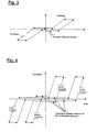
- Fig. 3 shows a flow-force diagram of a pressure valve according to the invention.
- Fig. 4 a flow-force diagram of a conventional pressure valve.
- a characteristic curve is shown during operation of the pressure valve.
- Fig. 3 has a hysteresis curve while Fig. 4 has two horizontally shifted hysteresis curves.
- the characteristic in Fig. 3 runs opposite to the characteristic in Fig. 4 with a flatter rise, wherein the characteristic curve corresponds approximately to a parallelogram, that is to say in the manner of a hysteresis curve.
- two such curves can be seen, both of which have a steeper slope.
- the characteristic curve in Fig. 3 due to the pressure compensation has no fluctuations in the closing forces, that is, the closing forces are constant due to the pressure equalization at all valve-side pressures.
- the power reserve in dynamic behavior of the valve is large, since no additional forces for the safe closing of the armature must be applied to the valve seat of the reset device.
- the forces to be applied by the electromagnet are also lower for opening. From the above results in a generally flatter characteristic curve, which can be better controlled than a steeper characteristic, since with a small deviation in one direction of the diagram, the effects in the other direction of the diagram are significantly lower than with steeper characteristics.
- the better control makes it easier to regulate disturbances or oscillations of the system, so that overall a less interference- and vibration-prone system is realized.
- FIG. 4 Diagram showing the behavior of a non-pressure-relieved system has two mutually shifted curves.
- the characteristic shift results from pre-pressure fluctuations so that a characteristic field (see FIG. 6) arises. This results in several work areas.
Description
Die Erfindung betrifft ein Elektromagnet, insbesondere ein Schalt- oder Proportionalmagnet zum Schalten eines vorgesteuerten Druckventils, umfassend ein Gehäuse zur Aufnahme und zum Schutz der weiteren Elektromagnetkomponenten, mindestens eine in dem Gehäuse angeordnete, elektrisch beaufschlagbare Spule zur Erzeugung eines Magnetfeldes, mindestens ein in dem Magnetfeld angeordneten, linear bewegbar, als Stellglied ausgebildeten Anker mit LK:JS zwei axial gegenüberliegenden Ankerflächen und eine mit dem Anker zusammenwirkende Rückstellvorrichtung, wobei der Anker so ausgebildet ist, dass dieser einen Ventilsitz eines mit dem Elektromagneten zusammenwirkenden Druckventils verschließt oder öffnet.The invention relates to an electromagnet, in particular a switching or proportional solenoid for switching a pilot-operated pressure valve, comprising a housing for receiving and protecting the further solenoid components, at least one arranged in the housing, electrically acted coil for generating a magnetic field, at least one in the magnetic field arranged, linearly movable, designed as an actuator armature with LK: JS two axially opposing armature surfaces and a return device cooperating with the armature, wherein the armature is formed so that it closes or opens a valve seat of a pressure valve cooperating with the electromagnet.
Derartige Elektromagneten kommen üblicherweise als Antriebseinheit von Ventilen zum Einsatz. Beim Einsatz in Ventilen wird allgemein zwischen Schaltmagneten und Proportionalmagneten unterschieden. Insbesondere beim Einsatz in Druckventilen, genauer in Druckregelventilen, welche die Aufgabe haben, den Druck in Druckluftleitungen und - systemen auch bei schwankendem Netz- oder Speisedruck und bei unterschiedlicher Abnahme auf einem konstanten Wert zu halten, werden vorzugsweise Proportionalmagneten eingesetzt. Deshalb kommen gerade auch bei vorgesteuerten Druckregelventilen Proportionalelektromagneten zum Einsatz.Such electromagnets are commonly used as a drive unit of valves. When used in valves, a distinction is generally made between solenoids and proportional solenoids. Especially when used in pressure valves, more precisely in pressure control valves, which have the task of keeping the pressure in compressed air lines and systems at a constant value even with fluctuating mains or feed pressure and with different decreases, proportional solenoids are preferably used. That is why proportional solenoids are also used in pilot-operated pressure control valves.
Allgemein sind Elektromagneten zum Einsatz in Ventilen bekannt. Diese Elektromagneten umfassen ein Gehäuse, welches mindestens eine elektrisch beaufschlagbare Spule zur Erzeugung eines Magnetfeldes umgibt, und einen in dem Magnetfeld bewegbar angeordneten Anker der als Stellglied mit einer einen ventilsitzabdichtenden Fläche ausgebildet ist und mindestens einer Rückstellvorrichtung, welche mit dem Anker zusammenwirkt und eine gegen die ventilsitzabdichtende Fläche wirkende Kraft auf den Anker einbringt.In general, electromagnets are known for use in valves. These electromagnets comprise a housing, which surrounds at least one electrically pressurizable coil for generating a magnetic field, and an armature movably arranged in the magnetic field which is designed as an actuator with a valve seat sealing surface and at least one restoring device, which cooperates with the armature and against the Valve seat sealing surface acting force on the anchor brings.
Bei der bekannten Lösung tritt der Nachteil auf, dass die Rückstellvorrichtung so ausgelegt werden muss, dass zu der für die Rückstellung des Stellglieds ohne Druckbeaufschlagung aufzuwendenden Kraft zusätzlich eine durch die Druckbeaufschlagung erforderliche Kraft von der Rückstellvorrichtung aufgebracht werden muss. Somit ist die Feder größer ausgelegt, als dies eigentlich für die Erzeugung einer zu Abdichtung notwendigen Rückstellkraft erforderlich wäre. Die Feder benötigt somit mehr Bauraum, was insgesamt entweder zu größeren Elektromagneten und somit zu größeren Ventilen oder zu einer suboptimalen Ausnutzung des Bauraums führt, wodurch nicht die größtmögliche Ventilnennweite hergestellt werden kann.In the known solution, the disadvantage arises that the return device must be designed so that in addition to be expended for the provision of the actuator without pressurization force required by the pressurization force from the return device must be applied. Thus, the spring is designed to be larger than would actually be necessary for the generation of a restoring force necessary for sealing. The spring thus requires more space, which in total either to larger electromagnets and thus to larger valves or to a suboptimal Exploitation of the space leads, whereby not the largest possible valve nominal width can be produced.
Aus der
Es ist die Aufgabe der vorliegenden Erfindung einen Elektromagneten der vorstehend beschriebenen Art zu schaffen, der eine Druckentlastung des Ankers beziehungsweise des Stellgliedes bewirkt, so dass die Rückstellvorrichtung optimal auslegbar ist und eine optimale Bauraunausnutzung realisierbar ist.It is the object of the present invention to provide an electromagnet of the type described above, which causes a pressure relief of the armature or of the actuator, so that the return device is optimally interpretable and optimal Bauraunausnutzung can be realized.
Diese Aufgabe wird ausgehend von einem Elektromagneten gemäß dem Oberbegriff des Anspruchs 1 in Verbindung mit dessen kennzeichnenden Merkmalen gelöst. Vorteilhafte Weiterbildungen der Erfindung sind in den abhängigen Ansprüchen angegeben.This object is achieved on the basis of an electromagnet according to the preamble of
Die Erfindung schließt die technische Lehre ein, dass der Anker Mittel zum Druckausgleich bei ventilsitzseitig druckbeaufschlagter erster Ankerfläche aufweist, so dass die LK:hvThe invention includes the technical teaching that the armature has means for pressure equalization at valve seat side pressure-loaded first anchor surface, so that the LK: hv
Rückstellvorrichtung mit einer Kompensationskraft zusammen an einer zweiten, der ersten Ankerfläche entgegengerichteten Ankerfläche wirkt, wodurch die Rückstellvorrichtung nur entsprechend der aufzubringenden Dichtkraft für den Ventilsitz auslegbar ist.Return device cooperates with a compensation force on a second, the first armature surface opposing armature surface, whereby the return device is interpretable only in accordance with the applied sealing force for the valve seat.
Diese Lösung bietet den Vorteil, dass durch den Druckausgleich ein von einer Seite mit Druck beaufschlagter Anker zusätzlich mit einem entgegengerichteten Gegendruck beaufschlagt wird, wodurch die beiden Drücke entsprechend entgegengesetzt wirken und somit ein Druckausgleich geschaffen ist Hierdurch wirkt alleine die Kraft der Rückstellvorrichtung. Diese Rückstellvorrichtung lässt sich so optimal auf die entsprechenden Anforderungen auslegen und dementsprechend lässt sich auch der Bauraum für die Rückstellvorrichtung, damit des Elektromagneten und schließlich des Ventils oder der entsprechenden Vorrichtung, mit der der Elektromagnet zusammenwirkt, auslegen.This solution offers the advantage that an equilibrium pressure applied from one side of the armature is additionally acted upon by an opposing counterpressure, whereby the two pressures act correspondingly opposite and thus a pressure compensation is created by the pressure acting alone the force of the reset device. This reset device can thus optimally interpret the corresponding requirements and accordingly can also be the space for the return device, so that the electromagnet and finally the valve or the corresponding device with which the solenoid cooperates design.
Zudem ändern sich durch die veränderten Kräfteverhältnisse verschiedene Parameter wie zum Beispiel die Ansprechzeit des Ankers, so dass bei Einsatz in einem Regelsystem mit beispielsweise einem Druckregelventil ein stabilerer Regelkreis gegenüber einem Regelkreis mit herkömmlichen Elektromagneten realisiert ist.In addition, changed by the changed balance of power various parameters such as the response time of the armature, so that when used in a control system with For example, a pressure control valve a more stable control loop is realized with respect to a control circuit with conventional electromagnets.
Erfindungsgemäß ist ein Anker in dem Elektromagnet zylindrisch ausgebildet mit zwei Stirnflächen, die axial zueinander angeordnet sind. Eine Stirnfläche ist so ausgebildet, dass diese einen Ventilsitz eines mit dem Elektromagneten zusammenwirkenden Ventils schließt.According to the invention, an armature in the electromagnet is cylindrically formed with two end faces, which are arranged axially to one another. An end face is formed to close a valve seat of a valve cooperating with the solenoid.
Die Rückstellvorrichtung kann als Feder-Speicher-Einheit ausgebildet sein und wirkt gegen den ventilseitigen Druck.The return device may be formed as a spring-storage unit and acts against the valve-side pressure.
Eine weitere, die Erfindung verbessernde Maßnahme sieht vor, dass die Mittel mindestens eine Leitung umfassen, die den ventilseitig an der ersten Ankerfläche anliegenden Druck an eine der ventilseitigen, ersten Ankerfläche entgegenwirkenden zweiten Ankerfläche leitet, so dass ein Gegendruck, der gegen den ventilseitig anliegenden Druck wirkt, realisiert ist. Durch die Weiterleitung des an der ersten Ankerfläche anliegenden Drucks an die zweite Ankerfläche wirkt unabhängig von dem Druckwert auf beiden Ankerseiten im Wesentlichen derselbe Druck. Hierdurch lässt sich auf einfache Weise eine Druckentlastung beziehungsweise ein Druckausgleich realisieren.A further measure improving the invention provides that the means comprise at least one line which directs the pressure applied to the first armature surface on the valve side first armature surface counteracting second armature surface, so that a back pressure against the valve side pressure applied works, is realized. Due to the forwarding of the pressure applied to the first armature surface to the second armature surface, essentially the same pressure acts on both armature sides independently of the pressure value. As a result, a pressure relief or pressure equalization can be realized in a simple manner.
Deshalb sieht eine weitere die Erfindung verbessernde Maßnahme vor, dass die mit dem Gegendruck beaufschlagbare zweite Ankerfläche im Wesentlich so ausgebildet ist, dass diese in axialer Richtung eine im Wesentlichen gleichgroße Fläche aufweist, wie die mit dem Druck beaufschlagte, ventilseitige erste Ankerfläche, um den Druckausgleich des Ankers zu realisieren.Therefore, another measure improving the invention provides that the second armature surface, which can be acted upon by the counter-pressure, is essentially designed such that it has a substantially equal area in the axial direction, such as the pressure-exerted valve-side first armature surface, to equalize the pressure to realize the anchor.
Die erste Ankerfläche ist mit einem Druck p1 beaufschlagt, der auf die erste Ankerfläche mit dem Flächeninhalt oder Flächenquerschnitt A1 wirkt. Dadurch ergibt sich eine erste Kraft F1, die ventilseitig auf den Anker beziehungsweise das Stellglied wirkt. Die Kraft F1 ist in axialer Richtung des Ankers in Richtung zweite Ankerfläche gerichtet.The first armature surface is acted upon by a pressure p 1 which acts on the first armature surface with the surface area or area cross section A 1 . This results in a first force F 1 , the valve side acts on the armature or the actuator. The force F 1 is directed in the axial direction of the armature in the direction of the second armature surface.
Die zweite Ankerfläche ist mit einem Druck p2 beaufschlagt, der auf die zweite Ankerfläche mit dem Flächeninhalt oder Flächenquerschnitt A2 wirkt. Dadurch ergibt sich eine zweite Kraft F2, die auf den Anker beziehungsweise das Stellglied wirkt. Die Kraft F2 ist in axialer Richtung des Ankers entgegengesetzt zur ersten Ankerfläche gerichtet.The second armature surface is acted upon by a pressure p 2, which acts on the second armature surface with the surface area or surface area A 2 . This results in a second force F 2 , which acts on the armature or the actuator. The force F 2 is directed in the axial direction of the armature opposite to the first armature surface.
Zudem wirkt auf die zweite Ankerfläche axial in Richtung erste Ankerfläche die Rückstellkraft FR der Rückstellvorrichtung. Diese entspricht einer notwendigen Abdichtkraft FA die entgegengesetzt zu FR wirkt.In addition, the restoring force F R of the restoring device acts on the second armature surface axially in the direction of the first armature surface. This corresponds to a necessary sealing force F A which acts opposite to F R.
Somit ergibt sich bei Berücksichtigung der vier vorgenannten Größen für die Kräfte in axialer Richtung das Kräfteverhältnis: F1 + FA= F2 + FR.F 1 + F A = F 2 + F R: Thus, the above four variables for the forces in the axial direction of the balance of forces results in consideration.
Wie zuvor beschrieben ergibt sich bei gleichem Druck p = p1 = p2 und bei gleichem Flächeninhalt A = A1 = A2 der Ankerfläche, dass bei nichtwirkendem Magnetfeld die Abdichtkraft FA ausschließlich von der Rückstellkraft FR der Rückstellvorrichtung bestimmt wird. Eine Einwirkung des Drucks ist somit nicht gegeben.As described above, at the same pressure, p = p 1 = p 2 and with the same surface area A = A 1 = A 2 of the armature surface, the sealing force F A is determined exclusively by the restoring force F R of the restoring device when the magnetic field is not active. An effect of the pressure is thus not given.
Eine die Erfindung weiter verbessernde Maßnahme lässt sich dadurch erzielen, dass die Leitung als längs koaxial durch den Anker verlaufende gerade Durchgangsöffnung ausgebildet ist, um den Druckausgleich zu realisieren. Auf diese Weise ist die Leitung in den Anker integriert, wodurch der Elektromagnet klein baut, da kein zusätzlicher Bauraum für ein Leitungssystem benötigt wird. Es wird außerdem kein zusätzliches Material benötigt, was weiterhin den positiven Effekt aufweist, dass der gesamte Elektromagnet leichter baut. Zudem stellt diese Durchgangsöffnung zugleich den kürzesten vorstellbaren Weg zur Realisierung eines erfindungsgemäßen Druckausgleichs dar. Die Durchgangsöffnung ist vorzugsweise als zylindrische Durchgangsbohrung ausgebildet.A further improvement of the invention measure can be achieved in that the line is designed as a longitudinally coaxial extending through the armature straight passage opening to realize the pressure equalization. In this way, the line is integrated into the armature, whereby the electromagnet builds small, since no additional space for a piping system is needed. It also requires no additional material, which further has the positive effect of making the entire electromagnet easier to build. In addition, this passage opening at the same time provides the shortest imaginable way to the realization a pressure equalization according to the invention. The passage opening is preferably formed as a cylindrical through hole.
Als besonders vorteilhaft hat sich herausgestellt, dass der Anker mindestens zweiteilig ausgebildet ist mit einem axial in dem Magnetfeld bewegbarem Vordruckankerteil und einem das Vordruckankerteil zumindest teilweise umgebenden, axial unbewegbar mit dem Vordruckankerteil verbundenen Arbeitsdruckankerteil, somit keine Relativbewegung zwischen Vordruckankerteil und Arbeitsdruckanker möglich ist, wobei Vordruckankerteil und Arbeitsdruckankerteil jeweils mindestens eine Durchgangsöffnung aufweisen, um den Druckausgleich zu realisieren. Auf diese Weise lässt sich auch bei mehreren auch unterschiedlichen Drücken ein Druckausgleich realisieren, wodurch das Einsatzgebiet des Elektromagneten signifikant erweitert ist. So lässt sich beispielsweise der Elektromagnet bei vorgesteuerten Ventilen einsetzen. Denkbar ist analog, dass der Anker mehrteilig ausgebildet ist, wodurch sich bei gleichem Durchmesser von stimseitigem Ventilsitz am Vordruckankerteil und dem Innendurchmesser des Dichtringes unterschiedlichste Druckbeaufschlagungen entsprechend ausgleichen lassen.Particularly advantageous has been found that the armature is formed at least two parts with an axially movable in the magnetic field Vordruckankerteil and the Vordruckankerteil at least partially surrounding axially immovably connected to the Vordruckankerteil Arbeitsdruckankerteil, thus no relative movement between Vordruckankerteil and working pressure anchor is possible, wherein Vordruckankerteil and working pressure anchor each have at least one passage opening to realize the pressure equalization. In this way, a pressure equalization can be realized even at several different pressures, whereby the field of application of the electromagnet is significantly extended. For example, the solenoid can be used with pilot operated valves. It is conceivable analogous that the armature is designed in several parts, which can compensate for the same diameter of stimseitigem valve seat on Vordruckankerteil and the inner diameter of the sealing ring correspondingly different pressurizations accordingly.
Vordruckankerteil und Arbeitsankerteil sind vorzugsweise aus verschiedenen Materialien hergestellt, wobei das Vordruckankerteil aus unmagnetischem Material hergestellt ist und das Arbeitsdruckankerteil aus magnetisch gut leitendem Material wie zum Beispiel Weicheisen hergestellt ist.The pre-pressure anchor part and working anchor part are preferably made of different materials, wherein the pre-pressure anchor part is made of non-magnetic material and the working pressure anchor part is made of magnetically highly conductive material such as soft iron.
Nach einer möglichen Weiterbildung der Erfindung wird vorgeschlagen, dass das Vordruckankerteil zumindest teilweise in der Durchgangsöffnung zum Druckausgleich des Arbeitsdruckankers axial unbewegbar angeordnet ist. Vorzugsweise ist die Durchgangsöffnung des Arbeitsdruckankers zentrisch angeordnet. Die Durchgangsöffnung kann durch zwei zusätzliche axiale Kanäle im Arbeitsdruckanker oder auch durch einen gewindeähnlichen Kanal im Arbeitsdruckankerteil oder außen auf dem Vordruckankerteil ausgebildet sein. Auch das Spiel zwischen der Führungsbuchse und dem Arbeitsdruckankerteil ließe sich als Leitung für den Arbeitsdruck nutzen, um einen Druckausgleich des Arbeitsdruckankers zu realisieren.According to a possible development of the invention it is proposed that the pre-pressure anchor part is arranged at least partially axially immovable in the passage opening for pressure equalization of the working pressure anchor. Preferably, the passage opening of the working pressure armature is arranged centrally. The passage opening can by two additional axial channels in the working pressure armature or by a thread-like channel in the working pressure anchor part or outside on the form anchor part be educated. Also, the game between the guide bush and the working pressure anchor part could be used as a conduit for the working pressure to realize a pressure equalization of the working pressure anchor.
Weiterhin vorteilhaft ist, dass die Rückstellvorrichtung als Druckfeder ausgebildet ist, die in einem zugleich als Druckraum dienenden Freiraum zwischen Gehäuse und Anker angeordnet ist, um eine Federkraft und eine durch den in dem Druckraum herrschenden Gegendruck hervorgerufene Druckkraft auf den Anker zu übertragen. Die Rückstellkraft, die hier als Federkraft ausgebildet ist, bestimmt ausschließlich die Abdichtkraft des Ankers. Dabei wirkt die Federkraft vorzugsweise in axialer Richtung. Die Druckfeder lässt sich platzsparend in dem Freiraum anordnen, so dass ein kleinbauender Elektromagnet realisiert ist. Durch den Druckausgleich ist eine entsprechend klein ausgelegte Feder verwendbar, so dass der Bauraum optimal ausgenutzt ist. Der Durchmesser des Ventilsitzes muss dabei gleich dem Innendurchmesser des Dichtringes auf dem Vordruckankerteil sein.It is also advantageous that the restoring device is designed as a compression spring, which is arranged in a serving as a pressure chamber clearance between the housing and anchor to transmit a spring force and caused by the pressure prevailing in the pressure chamber back pressure force on the armature. The restoring force, which is designed here as a spring force, determines exclusively the sealing force of the armature. The spring force preferably acts in the axial direction. The compression spring can be arranged to save space in the free space, so that a small-sized electromagnet is realized. Due to the pressure equalization a correspondingly small designed spring can be used, so that the space is optimally utilized. The diameter of the valve seat must be equal to the inner diameter of the sealing ring on the Vordruckankerteil.
Eine weitere Aufgabe der vorliegenden Erfindung ist es, ein Druckventil mit optimiertem Bauraum zu schaffen, welches trotz der geringen Abmaße beim Einsatz in einem Regelsystem einen stabilen Regelkreis ermöglicht.Another object of the present invention is to provide a pressure valve with optimized space, which allows a stable control loop despite the small dimensions when used in a control system.
Diese Aufgabe wird ausgehend von einem Druckventil gemäß dem Oberbegriff des Anspruchs in Verbindung mit dessen kennzeichnenden Merkmalen gelöst.This object is achieved on the basis of a pressure valve according to the preamble of the claim in conjunction with its characterizing features.
Die Erfindung schließt weiter die technische Lehre ein, dass ein Druckventil, insbesondere ein vorgesteuertes Proportional-Magnetventil mindestens ein erfindungsgemäßen Elektromagneten nach einem der Ansprüche 1 bis 7 umfasst, um ein druckausgeglichenes Druckventil zu realisieren. Mit dem Einsatz eines erfindungsgemäßen Elektromagneten lässt sich ein Druckventil mit optimiertem Bauraum und stabilen Regelkreis realisieren. Insbesondere lässt sich ein Druckregelventil und bevorzugt ein vordruckgesteuertes Druckregelventil realisieren, welches aufgrund des Druckausgleichs ein geringeres Magnetgewicht und damit verbunden einen stabileren Regelkreis aufweist.The invention further includes the technical teaching that a pressure valve, in particular a pilot-operated proportional solenoid valve comprises at least one electromagnet according to one of
Weitere die Erfindung verbessernde Maßnahmen sind in den Unteransprüchen angegeben oder werden nachstehend gemeinsam mit der Beschreibung eines bevorzugten Ausführungsbeispiels der Erfindung anhand der Figuren näher dargestellt. Es zeigt:
- Fig. 1
- eine Draufsicht eines erfindungsgemäßen Elektromagneten,
- Fig. 2
- einen Schnitt A-A des Elektromagneten nach
Fig. 1 , - Fig. 3
- ein Durchfluss-Kraft-Diagramm, mit der Darstellung des Durchflusses eines Fluids in Abhängigkeit von der vom erfindungsgemäßen Elektromagneten aufzubringenden Kraft und
- Fig. 4
- ein Durchfluss-Kraft-Diagramm nach
Fig. 3 eines herkömmlichen Ventils,
- Fig. 1
- a top view of an electromagnet according to the invention,
- Fig. 2
- a section AA of the electromagnet after
Fig. 1 . - Fig. 3
- a flow-force diagram, showing the flow of a fluid as a function of the force applied by the electromagnet according to the invention and
- Fig. 4
- a flow-force diagram after
Fig. 3 a conventional valve,
Zentrisch in dem Gehäuse ist ein Anker 3 angeordnet. Der Anker 3 ist entlang der Mittelachse des Elektromagneten 3 linear beziehungsweise axial beweglich angeordnet. In
Centric in the housing, an
Weiter ist in dem Gehäuse 2 eine elektrisch beaufschlagbare Spule 6 angeordnet, welche beim durchfließen mit elektrischem Strom ein Magnetfeld ausbildet. Die Spule 6 umgibt die beiden Ankerteile 3a, 3b, so dass diese innerhalb des durch die Spule 6, bei Beaufschlagung mit elektrischem Strom, gebildeten Magnetfelds angeordnet sind. Das Ankerteil 3a ist aus einem mit dem Magnetfeld zusammenwirkenden Material geformt, so dass die Ankerteile 3a und 3b durch das Magnetfeld bewegbar sind. Um die Bewegung des Arbeitsdruckankerteils 3a zu führen, ist eine Führungsbuchse vorgesehen, die das Arbeitsdruckankerteil 3a umgibt.
Das Vordruckankerteil 3b wird durch das Arbeitsdruckankerteil 3a, welches zylindrisch ausgebildet ist und eine Durchgangsöffnung aufweist. Hierzu ist das Arbeitsdruckankerteil 3a fest mit dem Arbeitsdruckankerteil 3b verbunden, so dass zwischen den beiden Arbeitsdruckankerteilen keine Relativbewegung möglich ist. Das Polstück liegt an der Innenseite des Gehäuses 2, genauer des Deckelbereichs des Gehäuses 2 an und bildet einen Freiraum 7, in den das Vordruckankerteil 3b mit einer zweiten Ankerfläche 8b mündet. In dem Freiraum 7 ist eine als Druckfeder ausgebildete Rückstellvorrichtung 9 angeordnet, die mit dem Vordruckankerteil 3b zusammenwirkt. Die Rückstellvorrichtung 9 liegt an der Innenseite des Deckelbereichs des Gehäuses 2 und an einem Absatz des Vordruckankerteils 3b an und wirkt so auf das Vordruckankerteil 3b. Durch die zweite Durchgangsöffnung 4b, das heißt die Durchgangsöffnung, die längs durch das Vordruckankerteil 3b verläuft, ist der Freiraum 7 und die Rückseite O-Rings 10 mit einem Druck p beaufschlagbar, der dem Druck p entspricht, der seitens des Ventils (nicht dargestellt) auf die erste Ankerfläche 5a und die Querschnittsfläche, welche die zweite Durchgangsöffnung 4b umgibt, wirkt. Somit wirkt auf die erste Ankerfläche 5b und die Querschnittsfläche um die zweite Durchgangsöffnung 4b und die Innendurchmesserfläche des O-Ringes 10 b vom Betrag her der gleiche Druck. Die Ankerfläche 5b, die Querschnittsfläche um die zweite Durchgangsöffnung 4b und die Innendurchmesserfläche des O-Rings 10 sind von ihrem Flächeninhalt gleich ausgebildet, so dass auf die Ankerfläche 5b und die Innendurchmesserfläche des O-Rings 10 vom Betrag die gleiche aber entgegengesetzt gerichtete Druckkraft wirkt.
Analog ist zwischen dem Bauteil zur Führung des Vordruckankerteils 3b und der Führungshülse zur Führung des Arbeitsdruckankerteils 3a ein Freiraum 7 ausgebildet, welcher mit einem ventilseitigen Druck pA durch die erste Durchgangsöffnung 4a längs durch das Arbeitsdruckankerteil 3a beaufschlagbar ist. Das Arbeitsdruckankerteil 3a weist eine zweite Ankerfläche 8a auf, die vom Flächeninhalt der ersten Ankerfläche 5a entspricht. Somit wirkt auf beide Ankerflächen 5a, 8a eine vom Betrag gleiche, aber entgegengesetzt gerichtete Druckkraft. Die beiden Freiräume 7 sind mittels eines Dichtrings voneinander abgedichtet. Das Vordruckankerteil 3b ist über eine nichtmetallische O-Ring-Haltescheibe mit dem Bauteil verbunden.Further, in the
The
Similarly, between the component for guiding the
In beiden
In both
Das in
Weiter weist der Verlauf der Kennlinie einen steileren Anstieg als in
- 11
- Elektromagnetelectromagnet
- 22
- Gehäusecasing
- 33
- Ankeranchor
- 3 a3 a
- ArbeitsdruckankerteilWorking pressure armature part
- 3 b3 b
- VordruckankerteilForm anchor part
- 44
- DurchgangsöffnungThrough opening
- 4 a4 a
- erste Durchgangsöffnungfirst passage opening
- 4 b4 b
- zweite Durchgangsöffnungsecond passage opening
- 5 a5 a
- erste Ankerflächefirst anchor surface
- 5 b5 b
- erste Ankerflächefirst anchor surface
- 66
- SpuleKitchen sink
- 77
- Freiraumfree space
- 8 a8 a
- zweite Ankerflächesecond anchor surface
- 8 b8 b
- zweite Ankerflächesecond anchor surface
- 99
- Druckvorrichtungprinting device
- 1010
- O-RingO-ring
Claims (6)
- A solenoid (1) for switching a pilot-controlled pressure valve, comprising a housing (2) for accommodating at least one electric coil (6) for generating a magnetic field, in which a linearly moveable armature (3) is arranged having two separate, axially opposite armature surfaces (5a, 5b; 8a, 8b), and cooperating with a return apparatus (9), wherein the armature (3) closes or opens a valve seat of a pressure valve cooperating with the solenoid (1), wherein the return apparatus (9) acts on the second armature surface (8a, 8b) by exerting a compensation force for pressure compensation at the armature (3), for which purpose the armature (3) has at least a two-part construction, and comprising a pre-pressurizing armature part (3b) axially moveable within the magnetic field, and a working pressure armature part (3a) at least partially surrounding the pre-pressurizing armature part (3b) and connected to the pre-pressurizing armature part (3b) in an axially fixed manner, wherein the pre-pressurizing part (3b) and the working pressure armature part (3a) each have at least one passage (4a, 4b),
characterised in that
the pre-pressurizing armature part (3b) is at least partially arranged in the passage (4a) in an axially fixed manner for pressure compensation of the working pressure armature (3a). - The solenoid (1) according to claim 1,
characterised in that
the means comprise at least one conduit that guides the pressure applied to the armature surface (5a, 5b) on the valve side, to a second armature surface (8a, 8b) acting in an opposed direction to the first armature surface (5a, 5b), so that a counterpressure is realized acting against the pressure applied on the side of the valve. - The solenoid (1) according to claim 1 or 2,
characterised in that
the second armature surface (8a, 8b) to which the counterpressure can be applied is essentially formed in such a way that it has a surface in the axial direction that has essentially the same size as the valve-side first armature surface (5a, 5b) to which the pressure is applied, in order to realize the pressure compensation of the armature (3). - The solenoid (1) according to any one of claims 1 to 3,
characterised in that
the conduit is formed as a straight passage (4) longitudinally and coaxially extending through the armature (3) in order to realize the pressure compensation. - The solenoid (1) according to any one of claims 1 to 4,
characterised in that
the return apparatus (9) is formed as a pressure spring arranged in a free space (7) between the housing (2) and the armature (3) and acting as a pressure cavity to transmit a force resulting from the spring force and the counterpressure present in the free space (7), to the armature (3). - A pressure valve, in particular a pilot-controlled proportional solenoid valve, comprising at least one solenoid (1) according to any one of claims 1 to 7, in order to realize a pressure-compensated pressure valve.
Applications Claiming Priority (2)
| Application Number | Priority Date | Filing Date | Title |
|---|---|---|---|
| DE10348171 | 2003-10-16 | ||
| DE2003148171 DE10348171A1 (en) | 2003-10-16 | 2003-10-16 | Electromagnet and pressure valve with electromagnet for switching a pilot operated pressure valve |
Publications (2)
| Publication Number | Publication Date |
|---|---|
| EP1524462A1 EP1524462A1 (en) | 2005-04-20 |
| EP1524462B1 true EP1524462B1 (en) | 2010-06-23 |
Family
ID=34353441
Family Applications (1)
| Application Number | Title | Priority Date | Filing Date |
|---|---|---|---|
| EP20040105085 Revoked EP1524462B1 (en) | 2003-10-16 | 2004-10-15 | Pressure balanced electromagnetic valve |
Country Status (2)
| Country | Link |
|---|---|
| EP (1) | EP1524462B1 (en) |
| DE (2) | DE10348171A1 (en) |
Families Citing this family (1)
| Publication number | Priority date | Publication date | Assignee | Title |
|---|---|---|---|---|
| CN111173800B (en) * | 2019-12-16 | 2021-09-17 | 河南平高电气股份有限公司 | Electrohydraulic control valve for hydraulic operating mechanism and electromagnetic pilot valve and pilot valve thereof |
Family Cites Families (3)
| Publication number | Priority date | Publication date | Assignee | Title |
|---|---|---|---|---|
| CH624196A5 (en) * | 1977-08-17 | 1981-07-15 | Ernst Franz Voegeli | Solenoid valve |
| DE3925794C2 (en) * | 1989-08-04 | 1996-03-14 | Bosch Gmbh Robert | Solenoid valve |
| US6832748B2 (en) * | 2001-12-05 | 2004-12-21 | Cummins Inc. | Outwardly opening, seat-sealed, force balanced, hydraulic valve and actuator assembly |
-
2003
- 2003-10-16 DE DE2003148171 patent/DE10348171A1/en not_active Withdrawn
-
2004
- 2004-10-15 DE DE200450011302 patent/DE502004011302D1/en active Active
- 2004-10-15 EP EP20040105085 patent/EP1524462B1/en not_active Revoked
Also Published As
| Publication number | Publication date |
|---|---|
| DE502004011302D1 (en) | 2010-08-05 |
| DE10348171A1 (en) | 2005-05-25 |
| EP1524462A1 (en) | 2005-04-20 |
Similar Documents
| Publication | Publication Date | Title |
|---|---|---|
| DE60104248T2 (en) | After both RIchtungen pilot-controlled valve assembly | |
| DE102005058846A1 (en) | Valve modular system with electromagnetically actuated valve | |
| DE3708248A1 (en) | 2-WAY VALVE | |
| DE112009005460B4 (en) | ELECTROMAGNETIC LINEAR VALVE | |
| EP0681128A1 (en) | Solenoid valve | |
| DE112018003806T5 (en) | Shock absorber | |
| EP1409873A1 (en) | Valve block for a control device, particularly for a hydrostatic machine | |
| DE602004006563T2 (en) | Magnetic actuator | |
| DE102019117233A1 (en) | Pressure return piston with annular shoulder | |
| DE2952237A1 (en) | PRESSURE CONTROL VALVE | |
| EP0667459B1 (en) | Electro-proportional solenoid-valve unit | |
| DE4423103C2 (en) | Electromagnetically actuated valve | |
| DE3305092A1 (en) | PRESSURE CONTROL VALVE | |
| DE3329734C2 (en) | ||
| EP0093340A2 (en) | Electropneumatic servo valve for a volume flow or pressure control | |
| DE10305157B4 (en) | Electromagnetic double-acting valve | |
| DE3134065A1 (en) | PRESSURE CONTROL VALVE | |
| DE102014226623A1 (en) | Pressure relief valve and thus equipped hydraulic machine | |
| DE19652410A1 (en) | Electropneumatic valve | |
| EP2813728B1 (en) | Piston slide valve | |
| EP1524462B1 (en) | Pressure balanced electromagnetic valve | |
| DE10030059B4 (en) | control device | |
| DE3430724A1 (en) | REEL ACTUATED HYDRAULIC VALVE | |
| DE19502671A1 (en) | Electromagnetically actuated fluid-flow control valve | |
| EP0135751B1 (en) | Hydraulic device |
Legal Events
| Date | Code | Title | Description |
|---|---|---|---|
| PUAI | Public reference made under article 153(3) epc to a published international application that has entered the european phase |
Free format text: ORIGINAL CODE: 0009012 |
|
| AK | Designated contracting states |
Kind code of ref document: A1 Designated state(s): AT BE BG CH CY CZ DE DK EE ES FI FR GB GR HU IE IT LI LU MC NL PL PT RO SE SI SK TR |
|
| AX | Request for extension of the european patent |
Extension state: AL HR LT LV MK |
|
| 17P | Request for examination filed |
Effective date: 20050923 |
|
| AKX | Designation fees paid |
Designated state(s): DE FR GB IT |
|
| 17Q | First examination report despatched |
Effective date: 20051115 |
|
| GRAP | Despatch of communication of intention to grant a patent |
Free format text: ORIGINAL CODE: EPIDOSNIGR1 |
|
| GRAS | Grant fee paid |
Free format text: ORIGINAL CODE: EPIDOSNIGR3 |
|
| GRAA | (expected) grant |
Free format text: ORIGINAL CODE: 0009210 |
|
| AK | Designated contracting states |
Kind code of ref document: B1 Designated state(s): DE FR GB IT |
|
| REF | Corresponds to: |
Ref document number: 502004011302 Country of ref document: DE Date of ref document: 20100805 Kind code of ref document: P |
|
| PLBI | Opposition filed |
Free format text: ORIGINAL CODE: 0009260 |
|
| 26 | Opposition filed |
Opponent name: PIERBURG GMBH Effective date: 20110322 |
|
| PLAX | Notice of opposition and request to file observation + time limit sent |
Free format text: ORIGINAL CODE: EPIDOSNOBS2 |
|
| REG | Reference to a national code |
Ref country code: DE Ref legal event code: R026 Ref document number: 502004011302 Country of ref document: DE Effective date: 20110322 |
|
| PLBB | Reply of patent proprietor to notice(s) of opposition received |
Free format text: ORIGINAL CODE: EPIDOSNOBS3 |
|
| PGFP | Annual fee paid to national office [announced via postgrant information from national office to epo] |
Ref country code: FR Payment date: 20121113 Year of fee payment: 9 |
|
| RDAF | Communication despatched that patent is revoked |
Free format text: ORIGINAL CODE: EPIDOSNREV1 |
|
| REG | Reference to a national code |
Ref country code: DE Ref legal event code: R103 Ref document number: 502004011302 Country of ref document: DE Ref country code: DE Ref legal event code: R064 Ref document number: 502004011302 Country of ref document: DE |
|
| PGFP | Annual fee paid to national office [announced via postgrant information from national office to epo] |
Ref country code: GB Payment date: 20121023 Year of fee payment: 9 |
|
| PGFP | Annual fee paid to national office [announced via postgrant information from national office to epo] |
Ref country code: DE Payment date: 20121217 Year of fee payment: 9 |
|
| RDAG | Patent revoked |
Free format text: ORIGINAL CODE: 0009271 |
|
| STAA | Information on the status of an ep patent application or granted ep patent |
Free format text: STATUS: PATENT REVOKED |
|
| 27W | Patent revoked |
Effective date: 20130217 |
|
| GBPR | Gb: patent revoked under art. 102 of the ep convention designating the uk as contracting state |
Effective date: 20130217 |
|
| REG | Reference to a national code |
Ref country code: DE Ref legal event code: R107 Ref document number: 502004011302 Country of ref document: DE Effective date: 20130814 |
|
| PGFP | Annual fee paid to national office [announced via postgrant information from national office to epo] |
Ref country code: IT Payment date: 20131029 Year of fee payment: 10 |