EP1524430B1 - Starter-generator with automatically reverting freewheel - Google Patents
Starter-generator with automatically reverting freewheel Download PDFInfo
- Publication number
- EP1524430B1 EP1524430B1 EP20040022895 EP04022895A EP1524430B1 EP 1524430 B1 EP1524430 B1 EP 1524430B1 EP 20040022895 EP20040022895 EP 20040022895 EP 04022895 A EP04022895 A EP 04022895A EP 1524430 B1 EP1524430 B1 EP 1524430B1
- Authority
- EP
- European Patent Office
- Prior art keywords
- hub
- shaft
- pulley
- springs
- spring
- Prior art date
- Legal status (The legal status is an assumption and is not a legal conclusion. Google has not performed a legal analysis and makes no representation as to the accuracy of the status listed.)
- Expired - Lifetime
Links
- 239000007858 starting material Substances 0.000 claims description 32
- 230000008878 coupling Effects 0.000 claims description 15
- 238000010168 coupling process Methods 0.000 claims description 15
- 238000005859 coupling reaction Methods 0.000 claims description 15
- 238000013016 damping Methods 0.000 claims description 6
- 238000002485 combustion reaction Methods 0.000 description 12
- 239000007789 gas Substances 0.000 description 3
- 239000007788 liquid Substances 0.000 description 3
- 238000000034 method Methods 0.000 description 3
- 208000032544 Cicatrix Diseases 0.000 description 1
- 230000007423 decrease Effects 0.000 description 1
- 230000000694 effects Effects 0.000 description 1
- 231100000241 scar Toxicity 0.000 description 1
- 230000037387 scars Effects 0.000 description 1
- 230000035939 shock Effects 0.000 description 1
- 238000011144 upstream manufacturing Methods 0.000 description 1
Images


Classifications
-
- F—MECHANICAL ENGINEERING; LIGHTING; HEATING; WEAPONS; BLASTING
- F02—COMBUSTION ENGINES; HOT-GAS OR COMBUSTION-PRODUCT ENGINE PLANTS
- F02N—STARTING OF COMBUSTION ENGINES; STARTING AIDS FOR SUCH ENGINES, NOT OTHERWISE PROVIDED FOR
- F02N15/00—Other power-operated starting apparatus; Component parts, details, or accessories, not provided for in, or of interest apart from groups F02N5/00 - F02N13/00
- F02N15/02—Gearing between starting-engines and started engines; Engagement or disengagement thereof
- F02N15/022—Gearing between starting-engines and started engines; Engagement or disengagement thereof the starter comprising an intermediate clutch
- F02N15/023—Gearing between starting-engines and started engines; Engagement or disengagement thereof the starter comprising an intermediate clutch of the overrunning type
-
- F—MECHANICAL ENGINEERING; LIGHTING; HEATING; WEAPONS; BLASTING
- F02—COMBUSTION ENGINES; HOT-GAS OR COMBUSTION-PRODUCT ENGINE PLANTS
- F02N—STARTING OF COMBUSTION ENGINES; STARTING AIDS FOR SUCH ENGINES, NOT OTHERWISE PROVIDED FOR
- F02N15/00—Other power-operated starting apparatus; Component parts, details, or accessories, not provided for in, or of interest apart from groups F02N5/00 - F02N13/00
- F02N15/02—Gearing between starting-engines and started engines; Engagement or disengagement thereof
-
- F—MECHANICAL ENGINEERING; LIGHTING; HEATING; WEAPONS; BLASTING
- F02—COMBUSTION ENGINES; HOT-GAS OR COMBUSTION-PRODUCT ENGINE PLANTS
- F02N—STARTING OF COMBUSTION ENGINES; STARTING AIDS FOR SUCH ENGINES, NOT OTHERWISE PROVIDED FOR
- F02N11/00—Starting of engines by means of electric motors
- F02N11/04—Starting of engines by means of electric motors the motors being associated with current generators
Definitions
- the invention relates to a starter with pulley, arranged inside the pulley shaft and a freewheel which has loaded by means of a spring device clamping body, with the features mentioned in the preamble of claim 1.
- Belt-driven starter generators for internal combustion engines of the generic type are known. They are a favored variant for a low-leakage start system, which is used in vehicles with automatic start-stop, because the occurring here tenfold the startup operations of the conventional single-track starter can not be used.
- WO 01/77520 A1 and WO 01/88369 A1 discloses devices for coupling a belt-driven starter generator with an internal combustion engine. These have a planetary gear with a sun gear, wherein the switching takes place at torque reversal active by coupling elements.
- Pulleys with freewheel, shortly belt freewheel disks are also described in the prior art. They have a free-running ring and clamping body with a spring device. These pulleys with freewheel described in the prior art can but are not used for the belt-driven starter generator, since when using the belt-driven starter generator in starter mode, ie as a motor to start an internal combustion engine, the torque in the opposite direction to the torque in generator mode, ie when the engine is running occurs.
- the starter generator according to the invention with the features mentioned in claim 1 offers the advantage over that the function of the known freewheeling pulley is fulfilled in the generator mode and opposite torques are transmitted in the starter operation.
- This is achieved by using a double freewheel in the belt-driven starter generator.
- the double freewheel has pairs of mutually associated clamping body, between which the spring device is arranged.
- the clamping body cooperate with different clamping gaps.
- the clamping bodies between the hub and the pulley are arranged with a control cage, which is coupled to the pulley.
- the coupling of the control cage takes place with the pulley by means of friction elements. Through this coupling, the switching of the double freewheel with torque reversal takes place.
- the advantage of a coupling by means of friction elements is that the coupling is not rigid, but is operatively connected. On the other hand, it is so rigid that with a movement of the pulley, the control cage performs the same movement as the pulley. When the direction of the pulley turns, so does the direction of movement of the control cage around.
- the springs of the spring coupling between shaft and hub have different stiffnesses.
- an angle range is connected upstream, which can transmit only small torques.
- This difference angle arises in particular at the start of the internal combustion engine and results from the non-uniform rotational speed of the internal combustion engine and from the, under its inertial mass uniformly rotating, starter generator. This nonuniformity is considerable only at the beginning of the starting process and decreases with increasing speed of the internal combustion engine.
- the springs are designed as spiral springs. The advantage here is that despite a small space, a large impact force is achieved.
- damping chambers which are filled with at least one medium may also be present. These damping chambers are formed between the driver of the shaft and the inner contour of the hub. They act like throttles. As a medium here gases with different compressibility properties or liquids with different viscosities can be used.
- the clearance angle of the spring coupling can be adjusted, namely by connecting in series of at least two hubs with drivers and associated springs.
- the geometric series connection of the hubs with drivers and associated springs can take place both on the axis of the shaft one behind the other, ie axially, as well as coaxially.
- Coaxial here means annularly arranged around the shaft scars.
- each of the inner hub represents the shaft for the next hub, so that multiple pairs of hub and shaft are realized with springs arranged therebetween. It is possible to increase the clearance angle by using different springs with different stiffness
- FIG. 1 shows an arrangement of a starter generator 1 with a shaft 3, which has a shaft axis 4 and is connected to the starter generator 1.
- the shaft 3 is part of a device 5, of which only a pulley 7 is shown in this figure.
- the pulley 7 is connected by means of a belt 9 with a pulley 11 of an internal combustion engine 15.
- the pulley 11 is connected to the engine 15 through a shaft 13.
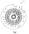
- FIG. 2 is the starter generator 1 according to the invention with the device 5 along the line II of FIG FIG. 1 shown arrangement shown. Identical parts are designated by the same reference numerals. It is going to the description too FIG. 1 directed to avoid repetition.
- the device 5 comprises the pulley 7, the shaft 3 of the starter generator 1 and a hub 19 arranged between the shaft 3 and the pulley 7.
- the shaft 3 has on an outer circumference 21 a driver 23 which is integrally connected to the shaft 3.
- the driver 23 has an almost rectangular base 25, which has almost vertical side surfaces 26 and 26 '. In the figure, only the rectangular base 25 is shown. A geometric dimension of the driver 23 in the direction of the shaft axis 4 can not be seen in the sectional view.
- the hub 19 has an inner contour 29. On the inner contour 29, a driver 31 is formed integrally with the hub 19. Of the driver 31 is also a base 33 shown in the figure.
- the base 33 of the hub 19 has a nearly perpendicular to the inner contour 29 of the hub 19 aligned side surfaces 35 and a nearly parallel to this side surface 35 '.
- a spring 37 is arranged between the side surface 35 'of the driver 31 and the side surface 26 of the driver 23.
- a spring 39 is arranged between the side surface 26 'of the driver 23 and the side surface 35 of the driver 33.
- the springs 37 and 39 have different stiffnesses. Rotates the shaft 3 clockwise, the spring 39 is compressed, the shaft 3 rotates counterclockwise, the spring 37 is compressed. If, however, the hub 19 rotates clockwise, the spring 37 is compressed and when the hub 19 is moved counterclockwise, the spring 39 is compressed.
- the shaft 3 and the hub 19 are thus rotatable relative to each other in accordance with the spring travel 37 and 39. It can be transmitted from the hub 19 on the shaft 3 torques and vice versa.
- Stiffnesses of the springs 37 and 39 is the necessary to transmit the same torque torsional angle of different sizes.
- the distance between the driver 23 and driver 31, which is adjustable by the springs 37 and 39, is referred to as clearance angle 41.
- the hub 19 has an outer contour 43. Between the outer contour 43 of the hub 19 and the pulley 7, a double freewheel 47 is arranged.
- the double freewheel 47 has at least two clamping elements 49 and 51 and a spring device 53 and a control cage 55 arranged between two clamping elements 49 and 51.
- the double freewheel has six of the at least two clamping elements 49 and 51, ie a total of twelve, each pairwise cooperating , Clamping elements.
- the control cage 55 is operatively connected to the pulley 7 via friction elements, not shown here, so that a torque is transmitted. This means that upon rotation of the pulley 7 in one direction, the control cage 55 is rotated in the same direction.
- the clamping elements 49 and 51 of the double freewheel 47 can be used in various embodiments, for example as a roller clamp or balls.
- hubs and shafts with springs in a row.
- the series connection of hubs and shafts can have axially successively connected shafts and hubs. It is also conceivable for hubs and shafts to be switched coaxially, that is to say onion-shaped, one behind the other, wherein an inner hub serves as a shaft for the outer hub.
- the driver 23 of the shaft 3 and the driver 31 of the hub 19 of the clearance angle 41 is formed. It is, as already described, also possible to switch hubs and shafts in succession, so that the resulting clearance angle is composed of the sum of the individual clearance angles between in each case a pair consisting of a hub and a shaft.
- the device 5 is shown in starter mode. Introduced by the shaft 3 right-handed torque, which is symbolized by the arrow 59 is on the soft spring 39, which is shown here in the block pressed state, from the driver 23 of the shaft 3 via the driver 31 of the hub 19 finally on the Hub 19 transferred. If the spring 39 is designed as a soft spring, that is to say with low spring rigidity, large shaft rotation angles and thus large difference angles to the hub 19 are produced even at low torques. The hub 19 begins to rotate, and thus the control cage 55, which is coupled via not shown friction elements with the pulley 7, through the pulley 7 withheld.
- a clamping gap 63 is released and the clamping body 49 transmits the clockwise torques, shown as arrow 59, from the hub 19 to the pulley 7.
- the clamping body 51 now form a self-releasing freewheel. That is, the clamp bodies 51, which are urged by the centrifugal force against the inner wall of the pulley 7, rotate with the pulley 7 as a rigid body, do not transmit moments, and do not make relative movement to the pulley 7. Rotates due to the nonuniformity of the internal combustion engine 15, the torque direction, the hub 19 is accelerated by the spring 39 due to the freewheel closed with clamping body 49.
- the freewheel 41 formed via the clamping bodies 49 opens.
- the freewheel 41 formed via the clamping bodies 51 can now close. It would have been transmitted at this time torques from the pulley 7 via the hub 19 to the shaft 3, which would have led to damage to the shaft 3, if the reversal of the freewheel of the clamping body would not have occurred. Therefore, the clearance angle 41 between the driver 23 and the driver 31 must be selected so that before the closing of the clamp body 51 of the torque input, which was caused by the reversal of the direction of the torque must be completed. It is particularly advantageous if this results in a compensatable by the spring 39 and the clearance angle 41 angular difference, which is greater than / equal to the largest difference angle during the startup process.
- the clearance angle 41 and thus the compensatable angular difference can be increased by hubs with drivers and springs are connected in series.
- series connection can be understood both an axial series connection of hubs and shafts, as well as a coaxial series connection analogous to a onion-like structure.
- coaxial series connection of hubs and shafts each of the outer side of a hub acts as a shaft for the next overlying hub.
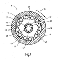
- FIG. 4 the device 5 is shown in the generator mode, ie with the internal combustion engine 15 running.
- a clockwise torque shown as arrow 65, moves the pulley 7 clockwise and tows by means of the friction elements, not shown, the control cage 55 with clockwise rotation.
- clamping gaps 61 are released for the clamping elements 51.
- the clamping elements 51 are moved by the springs 53 in clamping gaps 61 and thus transmit the clockwise torques 65 from the pulley 7 to the hub 19.
- the driver 31 transmits by the spring 37, the clockwise torque on the driver 23 on the shaft 3.
- the clamping body 49 are prevented by the control cage 55 from falling into the nip 63 and are forced outward by the centrifugal force, so that they rotate with the pulley 7 as a rigid body, so transmit no torque. They thus form a low-wear self-lifting freewheel.
- the shaft 3 rotates counterclockwise and the Driver 23 is moved to the driver 31 of the hub 19 and thus transmits the left-handed torque 69 to the hub 19.
- the rotation of the hub 19 in the counterclockwise direction of the clamping body 51 is moved to the clamping body 49 to. Since the pulley 7 is not in motion, the control cages 55 remain at rest and the nip 61 is released.
- the springs 53 press the clamping bodies 49 located in front of the springs 53 into the clamping gaps 63 and thus transmit the torque 69 from the hub 19 to the pulley 7.
- the pulley 7 is thus rotated and tensions the belt 9 between the pulley 7 of the starter generator 1 and pulley 11 of the engine 15 against the negative drag torque of the engine 15, since the pulley 11 is at rest.
Landscapes
- Engineering & Computer Science (AREA)
- Chemical & Material Sciences (AREA)
- Combustion & Propulsion (AREA)
- Mechanical Engineering (AREA)
- General Engineering & Computer Science (AREA)
- Devices For Conveying Motion By Means Of Endless Flexible Members (AREA)
- Connection Of Motors, Electrical Generators, Mechanical Devices, And The Like (AREA)
Description
Die Erfindung betrifft einen Startergenerator mit Riemenscheibe, innerhalb der Riemenscheibe angeordneter Welle und einem Freilauf, der mittels einer Federeinrichtung belasteten Klemmkörper aufweist, mit den im Oberbegriff des Anspruchs 1 genannten Merkmalen.The invention relates to a starter with pulley, arranged inside the pulley shaft and a freewheel which has loaded by means of a spring device clamping body, with the features mentioned in the preamble of claim 1.
Riemengetriebene Startergeneratoren für Verbrennungsmotoren der gattungsgemäßen Art sind bekannt. Sie sind eine favorisierte Variante für ein verschließarmes Startsystem, welches in Fahrzeugen mit Start-Stop-Automatik zum Einsatz kommt, da durch die hierbei auftretende Verzehnfachung der Startvorgänge der konventionelle Einspurstarter nicht mehr verwendet werden kann. In
Riemenscheiben mit Freilauf, kurz Riemenfreilaufscheiben, werden ebenfalls im Stand der Technik beschrieben. Sie weisen einen Freilaufring und Klemmkörper mit einer Federeinrichtung auf. Diese im Stand der Technik beschriebenen Riemenscheiben mit Freilauf können aber für den riemengetriebenen Startergenerator nicht zum Einsatz kommen, da beim Einsatz des riemengetriebenen Startergenerator im Starterbetrieb, also als Motor zum Start eines Verbrennungsmotors, das Drehmoment in entgegengesetzter Richtung zum Drehmoment im Generatorbetrieb, also bei laufendem Verbrennungsmotor, auftritt.Pulleys with freewheel, shortly belt freewheel disks are also described in the prior art. They have a free-running ring and clamping body with a spring device. These pulleys with freewheel described in the prior art can but are not used for the belt-driven starter generator, since when using the belt-driven starter generator in starter mode, ie as a motor to start an internal combustion engine, the torque in the opposite direction to the torque in generator mode, ie when the engine is running occurs.
Aus der
Der erfindungsgemäße Startergenerator mit den im Anspruch 1 genannten Merkmalen bietet dem gegenüber den Vorteil, dass im Generatorbetrieb die Funktion der bekannten Freilaufriemenscheibe erfüllt wird und im Starterbetrieb entgegengesetzte Drehmomente übertragen werden. Dies wird durch den Einsatz eines Doppelfreilaufs im riemengetriebenen Startergenerator erreicht. Der Doppelfreilauf weist paarweise einander zugeordnete Klemmkörper auf, zwischen denen die Federeinrichtung angeordnet ist. Die Klemmkörper wirken mit unterschiedlichen Klemmspalten zusammen. Es ist eine die Welle umgebende Nabe vorgesehen, wobei zwischen Nabe und Welle eine Federkopplung mit mindestens zwei Federn vorgesehen ist. Die Klemmkörper zwischen Nabe und Riemenscheibe sind mit einem Steuerkäfig, der mit der Riemenscheibe gekoppelt ist, angeordnet.The starter generator according to the invention with the features mentioned in claim 1 offers the advantage over that the function of the known freewheeling pulley is fulfilled in the generator mode and opposite torques are transmitted in the starter operation. This is achieved by using a double freewheel in the belt-driven starter generator. The double freewheel has pairs of mutually associated clamping body, between which the spring device is arranged. The clamping body cooperate with different clamping gaps. There is provided a hub surrounding the shaft, wherein between the hub and shaft, a spring coupling is provided with at least two springs. The clamping bodies between the hub and the pulley are arranged with a control cage, which is coupled to the pulley.
Bevorzugt ist vorgesehen, dass die Koppelung des Steuerkäfigs mit der Riemenscheibe mittels Reibelementen erfolgt. Durch diese Kopplung erfolgt die Umschaltung des Doppelfreilaufs bei Drehmomentumkehr. Der Vorteil einer Kopplung mittels Reibelementen liegt darin, dass die Kopplung nicht starr ist, sondern wirkverbunden ist. Sie ist auf der anderen Seite so starr, dass bei einer Bewegung der Riemenscheibe der Steuerkäfig dieselbe Bewegung wie die Riemenscheibe ausführt. Wenn die Richtung der Riemenscheibe sich umdreht, sich damit auch die Bewegungsrichtung des Steuerkäfigs um.It is preferably provided that the coupling of the control cage takes place with the pulley by means of friction elements. Through this coupling, the switching of the double freewheel with torque reversal takes place. The advantage of a coupling by means of friction elements is that the coupling is not rigid, but is operatively connected. On the other hand, it is so rigid that with a movement of the pulley, the control cage performs the same movement as the pulley. When the direction of the pulley turns, so does the direction of movement of the control cage around.
Bevorzugt ist vorgesehen, dass die Federn der Federkopplung zwischen Welle und Nabe unterschiedliche Steifigkeiten aufweisen. Dadurch wird ein Winkelbereich vorgeschaltet, der lediglich kleine Drehmomente übertragen kann. Dadurch stellt sich eine "Lose" ein, wobei die "Lose" einen größeren Winkel aufweist als ein Differenzwinkel zwischen Riemenscheibe und Welle. Dieser Differenzwinkel ergibt sich insbesondere beim Start des Verbrennungsmotors und resultiert aus der ungleichförmigen Drehgeschwindigkeit des Verbrennungsmotors und aus dem, unter seiner trägen Masse gleichförmiger umlaufenden, Startergenerator. Diese Ungleichförmigkeit ist nur zu Beginn des Startvorgangs beachtlich groß und nimmt mit zunehmender Drehzahl des Verbrennungsmotors ab.It is preferably provided that the springs of the spring coupling between shaft and hub have different stiffnesses. As a result, an angle range is connected upstream, which can transmit only small torques. This results in a "loose", wherein the "lots" has a larger angle than a differential angle between the pulley and shaft. This difference angle arises in particular at the start of the internal combustion engine and results from the non-uniform rotational speed of the internal combustion engine and from the, under its inertial mass uniformly rotating, starter generator. This nonuniformity is considerable only at the beginning of the starting process and decreases with increasing speed of the internal combustion engine.
In einem bevorzugten Ausführungsbeispiel der Federkopplung zwischen Nabe und Welle sind die Federn als Spiralfedern ausgebildet. Vorteilhaft ist hierbei, dass trotz kleinem Bauraum eine große Wirkungskraft erreicht wird.In a preferred embodiment of the spring coupling between the hub and the shaft, the springs are designed as spiral springs. The advantage here is that despite a small space, a large impact force is achieved.
Zusätzlich zu der Wirkung der Federn können in einem weiteren bevorzugten Ausführungsbeispiel auch Dämpfungsräume vorhanden sein, die mit mindestens einem Medium gefüllt sind. Diese Dämpfungsräume bilden sich zwischen dem Mitnehmer der Welle und der Innenkontur der Nabe aus. Sie wirken wie Drosseln. Als Medium können hier Gase mit unterschiedlichen Kompressibilitätseigenschaften oder auch Flüssigkeiten mit unterschiedlichen Viskositäten verwendet werden.In addition to the effect of the springs, in a further preferred exemplary embodiment, damping chambers which are filled with at least one medium may also be present. These damping chambers are formed between the driver of the shaft and the inner contour of the hub. They act like throttles. As a medium here gases with different compressibility properties or liquids with different viscosities can be used.
In einem bevorzugten Ausführungsbeispiel kann der Freiwinkel der Federkopplung eingestellt werden, nämlich durch Hintereinanderschaltung von mindestens zwei Naben mit Mitnehmern und zugeordneten Federn. Die geometrische Hintereinanderschaltung der Naben mit Mitnehmern und zugeordneten Federn kann sowohl auf der Achse der Welle hintereinander, also axial, erfolgen, als auch koaxial. Koaxial bedeutet hier ringförmig um die Welle angeordnete Narben. Hierbei stellt jeweils die innenliegende Nabe die Welle für die nächste Nabe dar, sodass mehrere Paare aus Nabe und Welle mit dazwischen angeordneten Federn realisiert sind. Es ist möglich den Freiwinkel durch Verwendung verschiedener Federn mit unterschiedlicher Steifigkeit zu vergrößernIn a preferred embodiment, the clearance angle of the spring coupling can be adjusted, namely by connecting in series of at least two hubs with drivers and associated springs. The geometric series connection of the hubs with drivers and associated springs can take place both on the axis of the shaft one behind the other, ie axially, as well as coaxially. Coaxial here means annularly arranged around the shaft scars. Here, each of the inner hub represents the shaft for the next hub, so that multiple pairs of hub and shaft are realized with springs arranged therebetween. It is possible to increase the clearance angle by using different springs with different stiffness
- Figur 1:FIG. 1:
- Anordnung des erfindungsgemäßen riemengetriebenen Startergenerators und eines Verbrennungsmotors,Arrangement of the belt-driven starter generator according to the invention and an internal combustion engine,
- Figur 2:FIG. 2:
-
Längsschnitt des Startergenerator entlang der Linie I-I aus
Figur 1 in Ruhestellung,Longitudinal section of the starter generator along the line IIFIG. 1 at rest, - Figur 3:FIG. 3:
-
Längsschnitt des Startergenerators entlang der Linie I-I aus
Figur 1 im Starterbetrieb,Longitudinal section of the starter generator along the line IIFIG. 1 in starter mode, - Figur 4:FIG. 4:
-
Längsschnitt des Startergenerators entlang der Linie I-I aus
Figur 1 im Generatorbetrieb.Longitudinal section of the starter generator along the line IIFIG. 1 in generator mode.
In
Die Vorrichtung 5 weist die Riemenscheibe 7, die Welle 3 des Startergenerators 1 und eine zwischen der Welle 3 und der Riemenscheibe 7 angeordnete Nabe 19 auf. Die Welle 3 weist an einem äußeren Umfang 21 einen Mitnehmer 23 auf, der einstückig mit der Welle 3 verbunden ist. Der Mitnehmer 23 weist eine nahezu rechteckige Grundfläche 25 auf, die nahezu senkrechte Seitenflächen 26 und 26' besitzt. In der Figur ist lediglich die rechteckige Grundfläche 25 gezeigt. Eine geometrische Abmessung des Mitnehmers 23 in Richtung der Wellenachse 4 ist in der Schnittdarstellung nicht zu erkennen. Die Nabe 19 weist eine Innenkontur 29 auf. An der Innenkontur 29 ist einstückig mit der Nabe 19 ein Mitnehmer 31 ausgebildet. Von dem Mitnehmer 31 ist ebenfalls eine Grundfläche 33 in der Figur gezeigt. Die Grundfläche 33 der Nabe 19 weist eine nahezu senkrecht zur Innenkontur 29 der Nabe 19 ausgerichtete Seitenflächen 35 und eine zu dieser nahezu parallelen Seitenfläche 35' auf. Zwischen der Seitenfläche 35' des Mitnehmers 31 und der Seitenfläche 26 des Mitnehmers 23 ist eine Feder 37 angeordnet. Zwischen der Seitenfläche 26' des Mitnehmers 23 und der Seitenfläche 35 des Mitnehmers 33 ist eine Feder 39 angeordnet. Die Federn 37 und 39 weisen unterschiedliche Steifigkeiten auf. Dreht sich die Welle 3 rechtsdrehend wird die Feder 39 zusammengedrückt, dreht sich die Welle 3 linksdrehend wird die Feder 37 zusammengedrückt. Dreht sich hingegen die Nabe 19 rechtsdrehend wird die Feder 37 zusammengedrückt und wenn die Nabe 19 sich linksdrehend bewegt wird die Feder 39 zusammengedrückt. Die Welle 3 und die Nabe 19 sind also entsprechend den Federwegen 37 und 39 relativ zueinander verdrehbar. Dabei können von der Nabe 19 auf die Welle 3 Drehmomente übertragen werden und umgekehrt. Durch die unterschiedlichen Steifigkeiten der Federn 37 und 39 ist der zur Übertragung gleicher Drehmomente notwendige Verdrehwinkel unterschiedlich groß. Der Abstand zwischen Mitnehmers 23 und Mitnehmers 31, der durch die Federn 37 und 39 einstellbar ist, wird als Freiwinkel 41 bezeichnet.The
Die Nabe 19 weist eine Außenkontur 43 auf. Zwischen der Außenkontur 43 der Nabe 19 und der Riemenscheibe 7 ist ein Doppelfreilauf 47 angeordnet. Der Doppelfreilauf 47 weist mindestens zwei Klemmelemente 49 und 51 auf sowie ein zwischen zwei Klemmelementen 49 und 51 angeordnete Federeinrichtung 53 und einen Steuerkäfig 55. Im vorliegenden Ausführungsbeispiel weist der Doppelfreilauf sechs der mindestens zwei Klemmelemente 49 und 51 auf, also insgesamt zwölf, jeweils paarweise zusammenwirkende, Klemmelemente. Der Steuerkäfig 55 ist über hier nicht dargestellte Reibelemente mit der Riemenscheibe 7 wirkverbunden, so dass ein Drehmoment übertragen wird. Dies bedeutet, dass bei Drehung der Riemenscheibe 7 in eine Richtung der Steuerkäfig 55 in derselben Richtung mitgedreht wird. Folgt die Belastung des Steuerkäfigs 55 durch die mittels der Nabe 19 beaufschlagten Klemmelemente 49 oder 51 wird der Steuerkäfig 55 durch die mittels Reibelemente geleistete Kopplung mit der Riemenscheibe 7 daran gehindert durch die Nabe 19 gedreht zu werden. Die Klemmelemente 49 und 51 des Doppelfreilaufs 47 können in verschiedenen Ausführungen eingesetzt werden, beispielsweise als Rollenklemmkörper oder Kugeln.The
Es ist auch möglich mehrere Naben und Wellen mit Federn hintereinander zu schalten. Die Hintereinanderschaltung von Naben und Wellen kann axial hintereinander geschaltete Wellen und Naben aufweisen. Denkbar ist es auch Naben und Wellen koaxial, also zwiebelschalenförmig, hintereinander zu schalten, wobei eine innenliegende Nabe als Welle für die außenliegende Nabe dient.It is also possible to switch several hubs and shafts with springs in a row. The series connection of hubs and shafts can have axially successively connected shafts and hubs. It is also conceivable for hubs and shafts to be switched coaxially, that is to say onion-shaped, one behind the other, wherein an inner hub serves as a shaft for the outer hub.
Zwischen den Mitnehmern der Nabe 19 und der Welle 3 werden Räume gebildet, die vorzugsweise mit Medien gefüllt werden, die mehr oder weniger kompressibel sind, und so zu einer zusätzlichen Dämpfung von Stößen und Geräuschen führen. Es ist auch denkbar, dass die Federn durch Räume, die mit Medien gefüllt sind, ersetzt werden, so dass die Einstellung des Freiwinkels durch beispielsweise zwei mit unterschiedlich kompressiblen Gasen gefüllte Räume erfolgt. Es ist auch möglich, dass unterschiedlich große Drosseln durch die Räume ausgebildet werden. Unter Medien können Flüssigkeiten oder auch Gase verstanden werden. Allgemein gesagt können Flüssigkeiten Gegenkräfte aufnehmen und damit eine Dämpfung der Relativbewegung bewirken. Die Dämpfung kann eingestellt werden durch die Wahl des Mediums und dadurch dass die Räume mit mehr oder weniger großen Drosseln zusammenwirken durch die das jeweilige Medium ein- und ausströmt.Between the drivers of the
Zwischen dem Mitnehmer 23 der Welle 3 und dem Mitnehmer 31 der Nabe 19 wird der Freiwinkel 41 ausgebildet. Es ist, wie bereits beschrieben, auch möglich Naben und Wellen hintereinander zu schalten, so dass der resultierende Freiwinkel sich aus der Summe der einzelnen Freiwinkel zwischen jeweils einem Paar, bestehend aus einer Nabe und einer Welle, zusammensetzt.Between the
In
Der Freiwinkel 41 und damit die ausgleichbare Winkeldifferenz, kann vergrößert werden, indem Naben mit Mitnehmern und Federn hintereinander geschaltet werden. Unter Hintereinanderschaltung kann sowohl eine axiale Hintereinanderschaltung von Naben und Wellen verstanden werden, als auch eine koaxiale Hintereinanderschaltung analog einem zwiebelartigem Aufbau. Bei der koaxialen Hintereinanderschaltung von Naben und Wellen fungiert jeweils die Außenseite einer Nabe als Welle für die nächste darüber liegende Nabe.The
In
Vor dem Starten des Verbrennungsmotors 15 ist es notwendig, trotz Einsatz eines Riemenspanners in der Seite des Riemens 9, die zwischen Riemenscheibe 7 und Riemenscheibe 11 liegt, die Riemenspannung in dem Bereich des Riemens 9 der zwischen der Riemenscheibe 7 des Startergenerators 1 und der Riemenscheibe 11 des Verbrennungsmotors 15 liegt, unter Last zu setzten. Hierzu wird die Riemenscheibe 7 des Startergenerators 1 entgegen dem Uhrzeigersinn in Linksrichtung gedreht. Da die Riemenscheibe 11 des Verbrennungsmotors 15 in Ruhe ist, spannt sich der Riemen 9 zwischen Riemenscheibe 7 des Startergenerators 1 und Riemenscheibe 11 des Verbrennungsmotors 15. In der Vorrichtung 5 stellen sich die in
Hierdurch wird eine bessere Verkeilung des Riemens 9 an einen während des Startvorgangs des Verbrennungsmotors 15 lastabgewandten Winkelbereichs der Riemenscheibe 11 des Verbrennungsmotors erreicht. Letztlich lässt sich so ein höheres anfängliches Startmoment übertragen, ohne dass es zu einem Durchrutschen des Riemens 9 kommt.As a result, a better wedging of the
Es ist ferner denkbar die Riemenscheibe 7 zusätzlich auch nur am Verbrennungsmotor 15 vorzusehen.It is also conceivable to additionally provide the
Claims (7)
- Starter alternator with a belt pulley, with a shaft arranged within the belt pulley and with a freewheel which has a clamping body loaded by means of a spring device, the freewheel being designed as a double freewheel, characterized in that the latter has clamping bodies (49, 51) which are assigned to one another in pairs and between which the spring device (53) is arranged and which cooperate with different clamping nips (61, 63), in that at least one hub (19) surrounding the shaft (3) is provided, in that the clamping bodies (49, 51) are arranged between the hub (19) and belt pulley (7) with a control cage (55) coupled to the belt pulley (7), and in that a spring coupling with at least two springs (37, 39) is provided between the hub (19) and shaft (3).
- Starter alternator according to Claim 1, characterized in that coupling between the control cage (55) and belt pulley (7) takes place by means of at least one friction element.
- Starter alternator according to Claims 1 and 2, characterized in that the at least two springs (37, 39) of the spring coupling have different rigidities, at least one first spring (37) acting in the event of a relative movement between the hub (19) and shaft (3), and at least one second spring (39) acting in the opposite direction in the event of a relative movement between the hub (19) and shaft (3).
- Starter alternator according to one of the preceding claims, characterized in that the springs (37, 39) are designed as helical springs.
- Starter alternator according to one of the preceding claims, characterized in that damping spaces filled with at least one medium are present between the drivers (23, 31).
- Starter alternator according to one of the preceding claims, characterized in that a clearance angle (41) between the driver (23) of the shaft (3) and the driver (31) of the hub (19) is determined by the rigidity of the springs (37, 39) of the spring coupling.
- Starter alternator according to one of the preceding claims, characterized in that the clearance angle (41) can be set by means of the series connection of at least two hubs (19) with driver (31) and assigned springs (37, 39).
Applications Claiming Priority (2)
| Application Number | Priority Date | Filing Date | Title |
|---|---|---|---|
| DE10347422 | 2003-10-13 | ||
| DE2003147422 DE10347422A1 (en) | 2003-10-13 | 2003-10-13 | Starter generator with self-switching freewheel |
Publications (3)
| Publication Number | Publication Date |
|---|---|
| EP1524430A2 EP1524430A2 (en) | 2005-04-20 |
| EP1524430A3 EP1524430A3 (en) | 2006-10-25 |
| EP1524430B1 true EP1524430B1 (en) | 2009-12-02 |
Family
ID=34353374
Family Applications (1)
| Application Number | Title | Priority Date | Filing Date |
|---|---|---|---|
| EP20040022895 Expired - Lifetime EP1524430B1 (en) | 2003-10-13 | 2004-09-25 | Starter-generator with automatically reverting freewheel |
Country Status (2)
| Country | Link |
|---|---|
| EP (1) | EP1524430B1 (en) |
| DE (2) | DE10347422A1 (en) |
Families Citing this family (4)
| Publication number | Priority date | Publication date | Assignee | Title |
|---|---|---|---|---|
| DE102009034339A1 (en) * | 2009-07-23 | 2011-01-27 | Bayerische Motoren Werke Aktiengesellschaft | Auxiliary unit drive for internal combustion engine of motor vehicle, has crankshaft for driving auxiliary unit by traction drive, and overhauling device provided between crankshaft and traction drive, where overhauling device is shiftable |
| DE102009035178A1 (en) | 2009-07-29 | 2011-02-10 | Daimler Ag | Free-wheel for starter of internal combustion engine of e.g. passenger car, has free wheel units and coupling elements that are mounted on one of units, and power transmission provided between units over spring element of coupling elements |
| DE102010000999B4 (en) * | 2010-01-19 | 2018-03-01 | Siemens Aktiengesellschaft | Dynamoelectric machine with rotor blocking device |
| DE112012000738A5 (en) * | 2011-02-09 | 2013-11-14 | Schaeffler Technologies AG & Co. KG | Method and device for starting an internal combustion engine |
Family Cites Families (6)
| Publication number | Priority date | Publication date | Assignee | Title |
|---|---|---|---|---|
| FR609501A (en) * | 1926-01-18 | 1926-08-16 | Improvements to elastic couplings | |
| DE635474C (en) * | 1932-12-13 | 1936-09-18 | Zahnradfabrik Friedrichshafen | Coupling device, especially for motor vehicles, with or in the forwards. Backward direction usable clamping bodies |
| US2209459A (en) * | 1938-03-03 | 1940-07-30 | Gen Motors Corp | Overrunning clutch |
| DE19919449B4 (en) * | 1998-05-04 | 2015-10-15 | Schaeffler Technologies AG & Co. KG | drive Windscreen |
| DE19852085C1 (en) * | 1998-11-12 | 2000-02-17 | Daimler Chrysler Ag | Two-stage starting system for internal combustion engine incorporates separate starter motors for low-speed and high-speed cranking |
| DE10253495A1 (en) * | 2001-12-14 | 2003-09-11 | Ina Schaeffler Kg | Free-wheel device for belt-driven starter generator has two axially offset free-wheel devices in annular gap with opposing working principles, direction dependent locking, free-wheel functions |
-
2003
- 2003-10-13 DE DE2003147422 patent/DE10347422A1/en not_active Ceased
-
2004
- 2004-09-25 EP EP20040022895 patent/EP1524430B1/en not_active Expired - Lifetime
- 2004-09-25 DE DE200450010439 patent/DE502004010439D1/en not_active Expired - Lifetime
Also Published As
| Publication number | Publication date |
|---|---|
| DE10347422A1 (en) | 2005-06-02 |
| EP1524430A3 (en) | 2006-10-25 |
| EP1524430A2 (en) | 2005-04-20 |
| DE502004010439D1 (en) | 2010-01-14 |
Similar Documents
| Publication | Publication Date | Title |
|---|---|---|
| DE3703123C2 (en) | Damping device | |
| EP3253980B1 (en) | Decoupler | |
| EP0863330B1 (en) | Mechanical torsional vibration damper | |
| EP0626523A1 (en) | Two-stage flexible coupling | |
| DE3009224C2 (en) | Overload clutch | |
| DE112015001500T5 (en) | Driving force transmission device and a manufacturing method for this device | |
| DE102016209598A1 (en) | Riemenscheibenentkoppler | |
| DE19525842A1 (en) | Torsional vibration damper with variable transmission | |
| DE4122841C2 (en) | Motor starter gear | |
| EP1524430B1 (en) | Starter-generator with automatically reverting freewheel | |
| DE102016211141A1 (en) | Riemenscheibenentkoppler | |
| DE202016003558U1 (en) | Riemenscheibenentkoppler | |
| DE102010045033B4 (en) | Coupling device for coupling two driven shafts with defined phase position and motor vehicle drive with two drive units and such a coupling device | |
| EP3892889A1 (en) | Wave gear drive | |
| DE102015200267B3 (en) | Riemenscheibenentkoppler | |
| DE102004043077B4 (en) | Device for generating a circumferential deformation of an elastic ring gear | |
| DE102019127672A1 (en) | Strain wave gear | |
| DE102015203283A1 (en) | Torque transmission device with tilting minimization in freewheeling unit | |
| CH659867A5 (en) | FREE COUPLING. | |
| DE102006059054B4 (en) | Torsional vibration damper with end shoes | |
| DE102010004579A1 (en) | Valve train for operation of valves of four cylinders of combustion engine, has camshaft with carriers having rotary driving units at front ends, respectively, where driving units of adjacent carriers are engaged in axially movable manner | |
| DE102020109755A1 (en) | Tension wave gear | |
| DE102013216882A1 (en) | Freewheel for use in drive train of motor vehicle, has spring unit comprising multiple preloaded compression springs that are clamped between switching and driving cages in circumferential direction | |
| DE102016200733B4 (en) | Generator pulley decoupler with optimized ramp mechanism to increase the torque capacity | |
| DE102009040002A1 (en) | Shaft-hub connection for transferring torque and power of shaft or pin to rotary hub of motor vehicle, has roller bodies radially movable along chute device, so that radially acting force is generated for clamping shaft and hub |
Legal Events
| Date | Code | Title | Description |
|---|---|---|---|
| PUAI | Public reference made under article 153(3) epc to a published international application that has entered the european phase |
Free format text: ORIGINAL CODE: 0009012 |
|
| AK | Designated contracting states |
Kind code of ref document: A2 Designated state(s): AT BE BG CH CY CZ DE DK EE ES FI FR GB GR HU IE IT LI LU MC NL PL PT RO SE SI SK TR |
|
| AX | Request for extension of the european patent |
Extension state: AL HR LT LV MK |
|
| PUAL | Search report despatched |
Free format text: ORIGINAL CODE: 0009013 |
|
| AK | Designated contracting states |
Kind code of ref document: A3 Designated state(s): AT BE BG CH CY CZ DE DK EE ES FI FR GB GR HU IE IT LI LU MC NL PL PT RO SE SI SK TR |
|
| AX | Request for extension of the european patent |
Extension state: AL HR LT LV MK |
|
| 17P | Request for examination filed |
Effective date: 20070425 |
|
| AKX | Designation fees paid |
Designated state(s): DE FR IT |
|
| 17Q | First examination report despatched |
Effective date: 20070606 |
|
| GRAP | Despatch of communication of intention to grant a patent |
Free format text: ORIGINAL CODE: EPIDOSNIGR1 |
|
| GRAS | Grant fee paid |
Free format text: ORIGINAL CODE: EPIDOSNIGR3 |
|
| GRAA | (expected) grant |
Free format text: ORIGINAL CODE: 0009210 |
|
| AK | Designated contracting states |
Kind code of ref document: B1 Designated state(s): DE FR IT |
|
| REF | Corresponds to: |
Ref document number: 502004010439 Country of ref document: DE Date of ref document: 20100114 Kind code of ref document: P |
|
| PLBE | No opposition filed within time limit |
Free format text: ORIGINAL CODE: 0009261 |
|
| STAA | Information on the status of an ep patent application or granted ep patent |
Free format text: STATUS: NO OPPOSITION FILED WITHIN TIME LIMIT |
|
| 26N | No opposition filed |
Effective date: 20100903 |
|
| PGFP | Annual fee paid to national office [announced via postgrant information from national office to epo] |
Ref country code: IT Payment date: 20140924 Year of fee payment: 11 |
|
| PGFP | Annual fee paid to national office [announced via postgrant information from national office to epo] |
Ref country code: DE Payment date: 20141126 Year of fee payment: 11 Ref country code: FR Payment date: 20140917 Year of fee payment: 11 |
|
| REG | Reference to a national code |
Ref country code: DE Ref legal event code: R119 Ref document number: 502004010439 Country of ref document: DE |
|
| PG25 | Lapsed in a contracting state [announced via postgrant information from national office to epo] |
Ref country code: IT Free format text: LAPSE BECAUSE OF NON-PAYMENT OF DUE FEES Effective date: 20150925 |
|
| REG | Reference to a national code |
Ref country code: FR Ref legal event code: ST Effective date: 20160531 |
|
| PG25 | Lapsed in a contracting state [announced via postgrant information from national office to epo] |
Ref country code: DE Free format text: LAPSE BECAUSE OF NON-PAYMENT OF DUE FEES Effective date: 20160401 |
|
| PG25 | Lapsed in a contracting state [announced via postgrant information from national office to epo] |
Ref country code: FR Free format text: LAPSE BECAUSE OF NON-PAYMENT OF DUE FEES Effective date: 20150930 |