EP1524409B1 - Dispositif de verrouillage d'aube - Google Patents
Dispositif de verrouillage d'aube Download PDFInfo
- Publication number
- EP1524409B1 EP1524409B1 EP04003299A EP04003299A EP1524409B1 EP 1524409 B1 EP1524409 B1 EP 1524409B1 EP 04003299 A EP04003299 A EP 04003299A EP 04003299 A EP04003299 A EP 04003299A EP 1524409 B1 EP1524409 B1 EP 1524409B1
- Authority
- EP
- European Patent Office
- Prior art keywords
- retaining ring
- blade
- retaining
- accordance
- arrangement
- Prior art date
- Legal status (The legal status is an assumption and is not a legal conclusion. Google has not performed a legal analysis and makes no representation as to the accuracy of the status listed.)
- Expired - Fee Related
Links
Images


Classifications
-
- F—MECHANICAL ENGINEERING; LIGHTING; HEATING; WEAPONS; BLASTING
- F01—MACHINES OR ENGINES IN GENERAL; ENGINE PLANTS IN GENERAL; STEAM ENGINES
- F01D—NON-POSITIVE DISPLACEMENT MACHINES OR ENGINES, e.g. STEAM TURBINES
- F01D5/00—Blades; Blade-carrying members; Heating, heat-insulating, cooling or antivibration means on the blades or the members
- F01D5/30—Fixing blades to rotors; Blade roots ; Blade spacers
- F01D5/32—Locking, e.g. by final locking blades or keys
- F01D5/326—Locking of axial insertion type blades by other means
-
- F—MECHANICAL ENGINEERING; LIGHTING; HEATING; WEAPONS; BLASTING
- F01—MACHINES OR ENGINES IN GENERAL; ENGINE PLANTS IN GENERAL; STEAM ENGINES
- F01D—NON-POSITIVE DISPLACEMENT MACHINES OR ENGINES, e.g. STEAM TURBINES
- F01D5/00—Blades; Blade-carrying members; Heating, heat-insulating, cooling or antivibration means on the blades or the members
- F01D5/30—Fixing blades to rotors; Blade roots ; Blade spacers
- F01D5/3007—Fixing blades to rotors; Blade roots ; Blade spacers of axial insertion type
- F01D5/3015—Fixing blades to rotors; Blade roots ; Blade spacers of axial insertion type with side plates
-
- F—MECHANICAL ENGINEERING; LIGHTING; HEATING; WEAPONS; BLASTING
- F05—INDEXING SCHEMES RELATING TO ENGINES OR PUMPS IN VARIOUS SUBCLASSES OF CLASSES F01-F04
- F05D—INDEXING SCHEME FOR ASPECTS RELATING TO NON-POSITIVE-DISPLACEMENT MACHINES OR ENGINES, GAS-TURBINES OR JET-PROPULSION PLANTS
- F05D2260/00—Function
- F05D2260/30—Retaining components in desired mutual position
-
- F—MECHANICAL ENGINEERING; LIGHTING; HEATING; WEAPONS; BLASTING
- F05—INDEXING SCHEMES RELATING TO ENGINES OR PUMPS IN VARIOUS SUBCLASSES OF CLASSES F01-F04
- F05D—INDEXING SCHEME FOR ASPECTS RELATING TO NON-POSITIVE-DISPLACEMENT MACHINES OR ENGINES, GAS-TURBINES OR JET-PROPULSION PLANTS
- F05D2300/00—Materials; Properties thereof
- F05D2300/50—Intrinsic material properties or characteristics
- F05D2300/501—Elasticity
Definitions
- the invention relates to a blade restraint according to the preamble of the main claim.
- the invention relates to a blade restraining device for the axial fixation of blades on a disc of a gas turbine, wherein connected to the blade, provided with a profiled blade root is inserted into an appropriate axial profile of the profile of the disc and axially by means of a split retaining ring is fixed, wherein the retaining ring is at least partially received in a groove of the Schaufelfu ⁇ es.
- a bucket restraint device for example, shows the US 6,234,756 B1 ,
- the DE 18 30 030 U discloses a blade retention device having a retaining ring which has a substantially rectangular cross-section and is inserted in a circumferential annular groove of the disc.
- the annular groove has a radially outer bearing surface for the retaining ring.
- the invention has for its object to provide a blade retaining device of the type mentioned, which is easy to assemble with a simple structure and simple, cost-effective applicability and has a low space requirement.
- the disc is provided with a circumferential annular groove which has an axially inner bearing surface for the retaining ring and that the retaining ring is elastically deformable at least in the axial direction.
- the blade restraining device according to the invention is characterized by a number of significant advantages.
- the blade restraining device according to the invention also allows installation in a multi-stage welded rotor in which at least one stage consists of blades which have an outlet opening in the blade root (micro-turbine).
- the invention enables a favorable introduction of the centrifugal forces below the blade root and thus a low weight of blade and disc. This also extends the life of the entire arrangement.
- the retaining ring can be configured as a sheet metal part, in comparison to the expensive forged parts known from the prior art.
- Another significant advantage results from an easier and faster installation and removal and the resulting cost savings.
- the installation of the blade restraint device according to the invention ensures a high repeatability and thus a high component reliability.
- the annular groove is provided with at least one insertion opening. Through this insertion, the retaining ring can be inserted or removed easily and without damage.
- the retaining ring consists of two or more layers of a metallic material, which are interconnected at one end of the retaining ring. As a result, the elasticity of the retaining ring is considerably increased. This in turn means that the retaining ring can be inserted into the groove and remains free of deformation in this.
- the retaining ring is provided with an anti-rotation device in order to prevent the retaining ring from wandering in the circumferential direction.
- the rotation is preferably formed in the form of a radially directed approach of the retaining ring, which is preferably provided at one end of the retaining ring.
- the retaining ring can be inserted and fixed by means of the rotation.
- the retaining ring has a strip-shaped cross section. By such a rectangular cross-section sufficient penetration of the retaining ring is ensured in the groove of the blade root or the disc.
- the retaining ring according to the invention may be divided in the scope of several segments, for example in six segments.
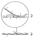
- the Fig. 1 shows a simplified representation of a rotatably mounted disc 2 of a gas turbine engine, to which a plurality of blades 1 are attached. Adjacent stator blades are provided with the reference numeral 10. Incidentally, reference may be made to the general structure of the prior art, so that it can be dispensed with its description.
- the blades 1 each have a blade root 3, which is provided with a profile which is insertable into a profiled axial groove 5 of the disc 2.
- a blade root 3 which is provided with a profile which is insertable into a profiled axial groove 5 of the disc 2.
- the lower portions of the blade roots 3 are each provided with a circumferential groove 6.
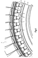
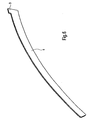
- the blade restraining device further comprises a divided into individual segments retaining ring 4, which is provided at its free end with a radially outwardly facing lug 9 (see in particular Fig. 6 ).
- the annular groove 7 has one or more insertion openings 8, which are realized by an interruption of the abutment leg 11. Through these insertion 8, it is possible to insert the elastically deformable in the axial direction retaining ring 4, as can be seen from the illustrations of FIGS. 2 and 3 results.
- upper disc grooves are also formed on the so-called disc fingers 12 (not shown), then the upper disc grooves would also have to be provided with corresponding insertion openings.
- the retaining ring 4 After the retaining ring 4 has been threaded, this snaps by its elasticity in the grooves 6 and 7 and is thus secured.
- This spring elasticity is caused in particular by the multi-layered design of the retaining ring 4.
- the retaining ring 4 consists of two or more layers, which are all connected at one end, for example, welded.
- the Versch discloseen can be done, for example, at the end at which the rotation is formed by means of the approach 9.
Landscapes
- Engineering & Computer Science (AREA)
- Mechanical Engineering (AREA)
- General Engineering & Computer Science (AREA)
- Turbine Rotor Nozzle Sealing (AREA)
- Structures Of Non-Positive Displacement Pumps (AREA)
Claims (8)
- Dispositif de verrouillage d'aubes (1) destiné à la fixation axiale d'aubes (1) sur un disque (2), comprenant un disque (2), des aubes (1) et un anneau de maintien segmenté (4), sachant qu'un pied d'aube (3) relié à l'aube (1) et doté d'un profil est introduit dans une gorge axiale (5) du disque (2) adaptée au profil, et est fixé dans le sens axial au moyen de l'anneau de maintien segmenté (4), que l'anneau de maintien (4) est logé au moins partiellement dans une gorge (6) du pied d'aube (3), que le disque (2) est muni d'une gorge annulaire circonférentielle (7) qui présente une surface d'appui radiale intérieure pour l'anneau de maintien (4) et que l'anneau de maintien (4) est déformable par élasticité au moins dans le sens axial, caractérisé en ce que l'anneau de maintien (4) est constitué de deux ou plusieurs couches qui sont reliées entre elles à une extrémité de l'anneau de maintien (4).
- Dispositif de verrouillage d'aubes selon la revendication n° 1, caractérisé en ce que la gorge annulaire (7) est munie d'au moins un orifice d'insertion (8).
- Dispositif de verrouillage d'aubes selon la revendication n° 1 ou n° 2, caractérisé en ce qu'est prévu un dispositif antirotation pour l'anneau de maintien (4).
- Dispositif de verrouillage d'aubes selon la revendication n° 3, caractérisé en ce que le dispositif antirotation comprend un talon (9) de l'anneau de maintien (4), qui est orienté dans le sens radial.
- Dispositif de verrouillage d'aubes selon une des revendications n° 3 ou n° 4, caractérisé en ce que le dispositif antirotation est prévu sur une extrémité de l'anneau de maintien (4).
- Dispositif de verrouillage d'aubes selon une des revendications n° 1 à n° 5, caractérisé en ce que l'anneau de maintien (4) a une section transversale lamellée.
- Dispositif de verrouillage d'aubes selon une des revendications n° 1 à n° 6, caractérisé en ce que l'anneau de maintien (4) est divisé en segments dans le sens circonférentiel.
- Dispositif de verrouillage d'aubes selon la revendication n° 7, caractérisé en ce que sont prévus six segments.
Applications Claiming Priority (2)
| Application Number | Priority Date | Filing Date | Title |
|---|---|---|---|
| DE10348198A DE10348198A1 (de) | 2003-10-16 | 2003-10-16 | Schaufelrückhaltevorrichtung |
| DE10348198 | 2003-10-16 |
Publications (3)
| Publication Number | Publication Date |
|---|---|
| EP1524409A2 EP1524409A2 (fr) | 2005-04-20 |
| EP1524409A3 EP1524409A3 (fr) | 2007-01-24 |
| EP1524409B1 true EP1524409B1 (fr) | 2011-08-10 |
Family
ID=34353443
Family Applications (1)
| Application Number | Title | Priority Date | Filing Date |
|---|---|---|---|
| EP04003299A Expired - Fee Related EP1524409B1 (fr) | 2003-10-16 | 2004-02-13 | Dispositif de verrouillage d'aube |
Country Status (3)
| Country | Link |
|---|---|
| US (1) | US7244105B2 (fr) |
| EP (1) | EP1524409B1 (fr) |
| DE (1) | DE10348198A1 (fr) |
Cited By (1)
| Publication number | Priority date | Publication date | Assignee | Title |
|---|---|---|---|---|
| US10876429B2 (en) | 2019-03-21 | 2020-12-29 | Pratt & Whitney Canada Corp. | Shroud segment assembly intersegment end gaps control |
Families Citing this family (12)
| Publication number | Priority date | Publication date | Assignee | Title |
|---|---|---|---|---|
| DE102004016977B4 (de) * | 2004-04-07 | 2006-11-23 | Mtu Aero Engines Gmbh | Rotor für eine Turbomaschine |
| US8105041B2 (en) * | 2005-09-07 | 2012-01-31 | Siemens Aktiengesellschaft | Arrangement for axially securing rotating blades in a rotor, sealing element for such an arrangement, and use of such an arrangement |
| DE102006054154B4 (de) * | 2006-11-16 | 2014-03-13 | Man Diesel & Turbo Se | Abgasturbolader |
| US8221083B2 (en) | 2008-04-15 | 2012-07-17 | United Technologies Corporation | Asymmetrical rotor blade fir-tree attachment |
| US8162615B2 (en) * | 2009-03-17 | 2012-04-24 | United Technologies Corporation | Split disk assembly for a gas turbine engine |
| FR2951224B1 (fr) * | 2009-10-13 | 2011-12-09 | Turbomeca | Roue de turbine equipee d'un jonc de retenue axiale verrouillant des pales par rapport a un disque |
| US9051845B2 (en) | 2012-01-05 | 2015-06-09 | General Electric Company | System for axial retention of rotating segments of a turbine |
| JP5675674B2 (ja) * | 2012-02-29 | 2015-02-25 | 三菱重工業株式会社 | タービン動翼の抜け止め構造およびこれを備えた回転機械 |
| US9140136B2 (en) | 2012-05-31 | 2015-09-22 | United Technologies Corporation | Stress-relieved wire seal assembly for gas turbine engines |
| US9366145B2 (en) | 2012-08-24 | 2016-06-14 | United Technologies Corporation | Turbine engine rotor assembly |
| US9790803B2 (en) | 2013-03-08 | 2017-10-17 | United Technologies Corporation | Double split blade lock ring |
| US10724384B2 (en) * | 2016-09-01 | 2020-07-28 | Raytheon Technologies Corporation | Intermittent tab configuration for retaining ring retention |
Family Cites Families (5)
| Publication number | Priority date | Publication date | Assignee | Title |
|---|---|---|---|---|
| DE1830030U (de) * | 1961-03-04 | 1961-04-27 | Gen Electric | Sicherung der schaufeln in den laeufern von turbinen, kompressoren od. dgl. |
| US3656865A (en) * | 1970-07-21 | 1972-04-18 | Gen Motors Corp | Rotor blade retainer |
| FR2603333B1 (fr) * | 1986-09-03 | 1990-07-20 | Snecma | Rotor de turbomachine comportant un moyen de verrouillage axial et d'etancheite d'aubes montees dans des brochages axiaux du disque et procede de montage |
| GB2258273B (en) * | 1991-08-02 | 1994-08-10 | Ruston Gas Turbines Ltd | Rotor blade locking arrangement |
| GB9517369D0 (en) * | 1995-08-24 | 1995-10-25 | Rolls Royce Plc | Bladed rotor |
-
2003
- 2003-10-16 DE DE10348198A patent/DE10348198A1/de not_active Withdrawn
-
2004
- 2004-02-13 EP EP04003299A patent/EP1524409B1/fr not_active Expired - Fee Related
- 2004-05-11 US US10/842,448 patent/US7244105B2/en not_active Expired - Fee Related
Cited By (1)
| Publication number | Priority date | Publication date | Assignee | Title |
|---|---|---|---|---|
| US10876429B2 (en) | 2019-03-21 | 2020-12-29 | Pratt & Whitney Canada Corp. | Shroud segment assembly intersegment end gaps control |
Also Published As
| Publication number | Publication date |
|---|---|
| DE10348198A1 (de) | 2005-05-12 |
| US7244105B2 (en) | 2007-07-17 |
| EP1524409A2 (fr) | 2005-04-20 |
| US20050084376A1 (en) | 2005-04-21 |
| EP1524409A3 (fr) | 2007-01-24 |
Similar Documents
| Publication | Publication Date | Title |
|---|---|---|
| EP1457640B1 (fr) | Redresseur tubulaire de vortex pour turbine à gaz et sa structure de support | |
| EP1714006B1 (fr) | Systeme amortisseur pour aubes directrices | |
| EP1524409B1 (fr) | Dispositif de verrouillage d'aube | |
| EP0906514B1 (fr) | Rotor pour une turbomachine avec des pales a monter dans des rainures et pales pour un rotor | |
| EP1584793B1 (fr) | Dispositif pour la fixation axiale d'aubes de turbine | |
| WO2007028703A1 (fr) | Systeme de retenue axiale de d'aubes mobiles dans un rotor et utilisation dudit systeme | |
| EP1650405A1 (fr) | Rotor d'une turbomachine, notamment rotor d'une turbine à gaz | |
| EP3999717B1 (fr) | Élément intermédiaire pour une connexion aube-disque de rotor pour le rotor d'une turbomachine, rotor pour une turbomachine et turbomachine | |
| EP1728972B1 (fr) | Dispositif de verrouillage d'une aube de turbine | |
| DE19828817C2 (de) | Rotor für eine Turbomaschine | |
| DE102008016329A1 (de) | Anordnung zum Auswuchten eines Rotors | |
| EP1840338B1 (fr) | Arrangement pour la fermeture axiale des palettes d'une turbine dans un rotor et gasturbine avec un tel arrangement | |
| EP1657404B1 (fr) | Rotor d'une turbomachine, notamment rotor d'une turbine à gaz | |
| EP1860291B1 (fr) | Paroi intermédiaire pour silencieux | |
| DE102010031213A1 (de) | Rotor einer Turbomaschine | |
| EP3379037B1 (fr) | Étanchéité sur une bague intérieure d'une couronne d'aubes directrices | |
| DE102016215807A1 (de) | Innenring für einen Leitschaufelkranz einer Strömungsmaschine | |
| WO2011018072A2 (fr) | Turbomachine | |
| EP3176385B1 (fr) | Boitier de stator pour une turbomachine et turbomachine comprenant un boitier de stator | |
| EP1350924B1 (fr) | Attachement des éléments de stator dans une turbine à gaz | |
| DE19823157A1 (de) | Einrichtung zur Befestigung der Laufschaufeln axial durchströmter Turbomaschinen | |
| WO2003100220A1 (fr) | Dispositif de securite axial pour aubes mobiles | |
| WO2005017320A1 (fr) | Rotor pour turbine a gaz, et turbine a gaz | |
| DE19757188A1 (de) | Einrichtung zur Befestigung der Laufschaufeln einstufiger Axialturbinen | |
| WO2003038240A1 (fr) | Dispositif d'arret pour des aubes mobiles de turbomachines a ecoulement axial |
Legal Events
| Date | Code | Title | Description |
|---|---|---|---|
| PUAI | Public reference made under article 153(3) epc to a published international application that has entered the european phase |
Free format text: ORIGINAL CODE: 0009012 |
|
| AK | Designated contracting states |
Kind code of ref document: A2 Designated state(s): AT BE BG CH CY CZ DE DK EE ES FI FR GB GR HU IE IT LI LU MC NL PT RO SE SI SK TR |
|
| AX | Request for extension of the european patent |
Extension state: AL LT LV MK |
|
| PUAL | Search report despatched |
Free format text: ORIGINAL CODE: 0009013 |
|
| AK | Designated contracting states |
Kind code of ref document: A3 Designated state(s): AT BE BG CH CY CZ DE DK EE ES FI FR GB GR HU IE IT LI LU MC NL PT RO SE SI SK TR |
|
| AX | Request for extension of the european patent |
Extension state: AL LT LV MK |
|
| RIN1 | Information on inventor provided before grant (corrected) |
Inventor name: MOELLER, TIM |
|
| 17P | Request for examination filed |
Effective date: 20070403 |
|
| 17Q | First examination report despatched |
Effective date: 20070604 |
|
| AKX | Designation fees paid |
Designated state(s): DE FR GB |
|
| GRAP | Despatch of communication of intention to grant a patent |
Free format text: ORIGINAL CODE: EPIDOSNIGR1 |
|
| GRAS | Grant fee paid |
Free format text: ORIGINAL CODE: EPIDOSNIGR3 |
|
| GRAA | (expected) grant |
Free format text: ORIGINAL CODE: 0009210 |
|
| AK | Designated contracting states |
Kind code of ref document: B1 Designated state(s): DE FR GB |
|
| REG | Reference to a national code |
Ref country code: GB Ref legal event code: FG4D Free format text: NOT ENGLISH |
|
| REG | Reference to a national code |
Ref country code: DE Ref legal event code: R096 Ref document number: 502004012768 Country of ref document: DE Effective date: 20111013 |
|
| PLBE | No opposition filed within time limit |
Free format text: ORIGINAL CODE: 0009261 |
|
| STAA | Information on the status of an ep patent application or granted ep patent |
Free format text: STATUS: NO OPPOSITION FILED WITHIN TIME LIMIT |
|
| 26N | No opposition filed |
Effective date: 20120511 |
|
| REG | Reference to a national code |
Ref country code: DE Ref legal event code: R097 Ref document number: 502004012768 Country of ref document: DE Effective date: 20120511 |
|
| REG | Reference to a national code |
Ref country code: DE Ref legal event code: R082 Ref document number: 502004012768 Country of ref document: DE Representative=s name: HOEFER & PARTNER, DE |
|
| REG | Reference to a national code |
Ref country code: DE Ref legal event code: R082 Ref document number: 502004012768 Country of ref document: DE Representative=s name: HOEFER & PARTNER, DE Effective date: 20130402 Ref country code: DE Ref legal event code: R081 Ref document number: 502004012768 Country of ref document: DE Owner name: ROLLS-ROYCE DEUTSCHLAND LTD & CO KG, DE Free format text: FORMER OWNER: ROLLS-ROYCE DEUTSCHLAND LTD & CO KG, 15827 BLANKENFELDE, DE Effective date: 20130402 Ref country code: DE Ref legal event code: R081 Ref document number: 502004012768 Country of ref document: DE Owner name: ROLLS-ROYCE DEUTSCHLAND LTD & CO KG, DE Free format text: FORMER OWNER: ROLLS-ROYCE DEUTSCHLAND LTD & CO KG, 15827 BLANKENFELDE, DE Effective date: 20110819 Ref country code: DE Ref legal event code: R082 Ref document number: 502004012768 Country of ref document: DE Representative=s name: HOEFER & PARTNER PATENTANWAELTE MBB, DE Effective date: 20130402 |
|
| PGFP | Annual fee paid to national office [announced via postgrant information from national office to epo] |
Ref country code: FR Payment date: 20140317 Year of fee payment: 11 |
|
| PGFP | Annual fee paid to national office [announced via postgrant information from national office to epo] |
Ref country code: GB Payment date: 20140227 Year of fee payment: 11 |
|
| PGFP | Annual fee paid to national office [announced via postgrant information from national office to epo] |
Ref country code: DE Payment date: 20140327 Year of fee payment: 11 |
|
| REG | Reference to a national code |
Ref country code: DE Ref legal event code: R119 Ref document number: 502004012768 Country of ref document: DE |
|
| GBPC | Gb: european patent ceased through non-payment of renewal fee |
Effective date: 20150213 |
|
| REG | Reference to a national code |
Ref country code: FR Ref legal event code: ST Effective date: 20151030 |
|
| PG25 | Lapsed in a contracting state [announced via postgrant information from national office to epo] |
Ref country code: DE Free format text: LAPSE BECAUSE OF NON-PAYMENT OF DUE FEES Effective date: 20150901 Ref country code: GB Free format text: LAPSE BECAUSE OF NON-PAYMENT OF DUE FEES Effective date: 20150213 |
|
| PG25 | Lapsed in a contracting state [announced via postgrant information from national office to epo] |
Ref country code: FR Free format text: LAPSE BECAUSE OF NON-PAYMENT OF DUE FEES Effective date: 20150302 |