EP1524365A1 - Low noise emission railway rail - Google Patents
Low noise emission railway rail Download PDFInfo
- Publication number
- EP1524365A1 EP1524365A1 EP03078290A EP03078290A EP1524365A1 EP 1524365 A1 EP1524365 A1 EP 1524365A1 EP 03078290 A EP03078290 A EP 03078290A EP 03078290 A EP03078290 A EP 03078290A EP 1524365 A1 EP1524365 A1 EP 1524365A1
- Authority
- EP
- European Patent Office
- Prior art keywords
- rail
- perforations
- railway
- running surface
- perforation
- Prior art date
- Legal status (The legal status is an assumption and is not a legal conclusion. Google has not performed a legal analysis and makes no representation as to the accuracy of the status listed.)
- Withdrawn
Links
Images


Classifications
-
- E—FIXED CONSTRUCTIONS
- E01—CONSTRUCTION OF ROADS, RAILWAYS, OR BRIDGES
- E01B—PERMANENT WAY; PERMANENT-WAY TOOLS; MACHINES FOR MAKING RAILWAYS OF ALL KINDS
- E01B5/00—Rails; Guard rails; Distance-keeping means for them
- E01B5/02—Rails
-
- E—FIXED CONSTRUCTIONS
- E01—CONSTRUCTION OF ROADS, RAILWAYS, OR BRIDGES
- E01B—PERMANENT WAY; PERMANENT-WAY TOOLS; MACHINES FOR MAKING RAILWAYS OF ALL KINDS
- E01B19/00—Protection of permanent way against development of dust or against the effect of wind, sun, frost, or corrosion; Means to reduce development of noise
- E01B19/003—Means for reducing the development or propagation of noise
-
- E—FIXED CONSTRUCTIONS
- E01—CONSTRUCTION OF ROADS, RAILWAYS, OR BRIDGES
- E01B—PERMANENT WAY; PERMANENT-WAY TOOLS; MACHINES FOR MAKING RAILWAYS OF ALL KINDS
- E01B5/00—Rails; Guard rails; Distance-keeping means for them
- E01B5/02—Rails
- E01B5/08—Composite rails; Compound rails with dismountable or non-dismountable parts
Definitions
- the invention relates to a low noise emission railway rail for guiding a wheel of a rail-guided vehicle, e.g. train or tram.
- Railway rails are commonly known and comprise a body having a running surface for cooperation of the wheel and a non-running surface.
- the rail comprises a longitudinally extending bar, having a cross section being built up of a foot portion that is connected via a web portion to a head portion, the running surface being formed by a part of the surface of the head portion, while the remainder of the surface of the head portion, and the surface of the web portion and the foot portion forms the non-running surface.
- the railway rails are usually incorporated in a rail track, comprising two substantially parallel rails supported on a base body, e.g. a track bed supporting a row of transverse sleepers that support the rails or continues support structure.
- a problem associated with rail-guided vehicles is that they generate noise as they are guided along the rails.
- a significant component of this noise is the rolling noise that is generated by rolling of the wheels along the running surface.
- the rolling noise is generated in substantially similar amounts by the vibrating wheels and by the vibrating track.
- noise reducing measures comprise additional elements that increase the need for inspection and maintenance.
- the invention aims to provide a rail with which the rolling noise generated by the rail can be reduced with minimal consequences for installation, costs, inspection and maintenance of the track.
- the railway rail is thereto provided with a plurality of perforations extending through the body from one part of the non-running surface to another part of the non-running surface, the average distance between two adjacent perforations being less than twice the diameter of the smallest enclosing circle of the cross sectional profile of the rail.
- the function of a perforation is to partly cancel the dynamic pressure difference in the surrounding medium, that arises from the dynamic movement of the rail body, by connecting regions of high dynamic pressure to regions of low dynamic pressure. This pressure cancelling reduces the ability of the rail body to generate sound waves in the surrounding medium.
- the rail By providing a rail with such perforations, a reduction in noise level of up to 10-15 dB can be achieved compared to an identical rail without perforations.
- the sound reducing effect of such a rail applied in a track system in combination with a train or tram strongly depends on the other components of the system as well.
- the reduction of the sound generated by the system may be as high as 5-10 dB.
- the rail comprises no additional elements, the need for inspection and maintenance can be the same as for normal rail without sound reducing perforations.
- the rail is also suitable as a direct replacement or retrofit of existing rails without any additional installation effort.
- the smallest enclosing circle of the rail profile is defined herein as the smallest circle in which the cross sectional profile that is normal to the longitudinal axis of the rail can be fully enclosed.
- the average distance between two adjacent perforations is comprised between 5 and 80 mm.
- the diameter of an average perforation is more than a tenth of the length of the perforation channel. This allows for a robust rail having high dampening characteristics.
- the distance between two adjacent perforations is the distance from the boundary of one perforation to the boundary of the next nearest perforation over the external surface of the body.
- the amount of rolling noise generated by the rail is reduced further when the average distance between any perforation and the nearest external boundary of the profile is less than 80 mm.
- the distance between any perforation and the external boundary is the distance from the boundary of the perforation to the external boundary of the profile as measured in the projection plane perpendicular to the axial centre line of the perforation channel.
- the distance as defined herein may be zero, which corresponds to a perforation that forms a notch.
- the railway rail comprises a profiled, longitudinally extending bar having a cross section being built up of a foot portion and a head portion that is connected via a web portion and wherein the head portion comprises the running surface.
- perforations preferably extend through the web portion, e.g. transversely between outer surfaces of the web portion.
- perforations extend between outer surfaces of the foot portion.
- the perforations are preferably free, but may be at least partially filled with an air permeable, solid material, e.g. a porous material.
- the invention also relates to a railway track, comprising at least two substantially parallel rails, supported on a base body.
- the invention further relates to a method of reducing the capacity of a rail to generate rolling noise, the method comprising a step of providing a body portion of the rail with perforations.
- perforations may e.g. be provided by drilling, milling or punching, but may also be provided by casting or rolling in foreign objects e.g. core portions, in the body portion and by subsequent removal of the core portions.
- the invention shall be elucidated using an example that is shown in a drawing. In the drawing.
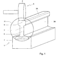
- Fig. 1 shows a railway rail 1 for guiding a wheel of a train.
- the rail 1 comprises a body 2 having a running surface 3A for cooperation with the corresponding running surface 4 of a wheel 5. The remainder of the outer surface of the body 2 forms the non-running surface 3B.
- the rail 1 forms part of a railway track comprising two substantially parallel rails being supported by a support body.
- the rails may be conventionally supported by a support body (not shown) on which a row of sleepers is provided that extend transversely to the rails and at the end of which the rails are connected by means of a clamp connection.
- the rails may be supported in other ways, e.g. by a base body provided with at least two recessed channels in each of which a rail is received such that the running surface of the rail lies free.
- the rail 1 comprises a profiled, longitudinally extending bar having a cross section built up of a foot portion 7 that is connected to a head portion 9 via a web portion 8.
- the remainder of the outer surface of the body 2 that forms the non-running surface 3B is formed by the rest of the outer surface of the head portion 9, the outer surface of the web portion 8 and the outer surface of the foot portion 7.
- the body 2 of the rail 1 is provided with a plurality of perforations 10, each perforation 10 extending through the body from one part of the non-running surface 3B to another part of the non-running surface 3B.
- the web portion 8 is provided with perforations 10a that extend substantially transversely to the longitudinal axis of the rail 1, i.e. in the direction of the width of the body 2.
- the perforations 10b in the foot portion 7 of the rail extend substantially transversely to the web portion 8, i.e. in the direction of the height of the body 2.
- the average distance (D1) between two adjacent perforations is less than twice the diameter of the smallest enclosing circle 11 of the cross-section that is normal to the longitudinal axis of the rail 1.
- the average distance D1 is preferably less than twice the maximum of the height (H) or the width (W) of the body 2.
- the average distance D2 between any perforation and the external boundary is comprised between 5 and 80 mm.
- the medium present in the perforations and surrounding the rail is air.
- the rail 1 has been produced by rolling of a steel bar. During rolling, the perforations have been provided by rolling foreign objects, e.g. thorns, spikes or core portions into the steel bar.
- foreign objects e.g. thorns, spikes or core portions into the steel bar.
- the perforations in the web portion are disposed near the neutral line for bending of the profile about an axis perpendicular to it's longitudinal axes.
- the perforations are distributed at spaced intervals about the length of the profile, such that any cross section of the profile normal to the longitudinal axis coincides with no more than one perforation.
- FIG. 3 another embodiment of the rail is shown in which the perforations are in the form of notches and have a distance D2 equal to zero. Such notches may be used together with perorations that have a distance greater than zero.
- the rail may e.g. comprise a large number of perforations having a small diameter and/or smaller number of perforations having a larger diameter.
- the perforations may have a circular cross-section, but may also have a cross-section of different or deferring shape. Perforations need not be holes, but may e.g. also be formed as notches. Perforations may be filled with an air permeable structure. Further, perforations in the rail may be formed by composing the body of the rail out of sub bodies. Also, perforations may be provided by using a porous material rather than a solid material. Many such variations will be apparent to the skilled man and are within the scope of the invention as defined in the following claims.
Landscapes
- Engineering & Computer Science (AREA)
- Architecture (AREA)
- Civil Engineering (AREA)
- Structural Engineering (AREA)
- Mechanical Engineering (AREA)
- Railway Tracks (AREA)
Abstract
Railway rail (1) for guiding a wheel of a rail guided vehicle, said rail comprising a body (2) having a running surface (3A) for cooperation with a wheel to be guided and non-running surface (3B) provided with a plurality of perforations (10) extending from one part of the non-running surface to another part of the non-running surface, the average distance (D1) between two adjacent perforations being less than twice the diameter of the smallest enclosing circle (11) of the cross sectional profile normal to the longitudinal axis of the rail. <IMAGE>
Description
The invention relates to a low noise emission railway rail for guiding
a wheel of a rail-guided vehicle, e.g. train or tram.
Railway rails are commonly known and comprise a body having a
running surface for cooperation of the wheel and a non-running surface.
Generally, the rail comprises a longitudinally extending bar, having
a cross section being built up of a foot portion that is connected via a web
portion to a head portion, the running surface being formed by a part of the
surface of the head portion, while the remainder of the surface of the head
portion, and the surface of the web portion and the foot portion forms the non-running
surface. The railway rails are usually incorporated in a rail track,
comprising two substantially parallel rails supported on a base body, e.g. a
track bed supporting a row of transverse sleepers that support the rails or
continues support structure.
A problem associated with rail-guided vehicles is that they generate
noise as they are guided along the rails. A significant component of this noise
is the rolling noise that is generated by rolling of the wheels along the running
surface. The rolling noise is generated in substantially similar amounts by the
vibrating wheels and by the vibrating track.
In the state of the art, a large number of noise-reducing measures to
the wheels and tracks have been proposed. With respect to noise reduction of
the track, these measures comprise rail dampers, rail clamps, alternative track
beds and alternative rail profiles.
Although some of these measures are effective, many are too
expensive and too costly to install for widespread application. In addition,
many noise reducing measures comprise additional elements that increase the
need for inspection and maintenance.
The invention aims to provide a rail with which the rolling noise
generated by the rail can be reduced with minimal consequences for
installation, costs, inspection and maintenance of the track. According the
invention, the railway rail is thereto provided with a plurality of perforations
extending through the body from one part of the non-running surface to
another part of the non-running surface, the average distance between two
adjacent perforations being less than twice the diameter of the smallest
enclosing circle of the cross sectional profile of the rail. The function of a
perforation is to partly cancel the dynamic pressure difference in the
surrounding medium, that arises from the dynamic movement of the rail body,
by connecting regions of high dynamic pressure to regions of low dynamic
pressure. This pressure cancelling reduces the ability of the rail body to
generate sound waves in the surrounding medium. By providing a rail with
such perforations, a reduction in noise level of up to 10-15 dB can be achieved
compared to an identical rail without perforations. The sound reducing effect
of such a rail applied in a track system in combination with a train or tram
strongly depends on the other components of the system as well. With the
perforated rails, the reduction of the sound generated by the system may be as
high as 5-10 dB. As the rail comprises no additional elements, the need for
inspection and maintenance can be the same as for normal rail without sound
reducing perforations. Further, the rail is also suitable as a direct replacement
or retrofit of existing rails without any additional installation effort.
The smallest enclosing circle of the rail profile is defined herein as
the smallest circle in which the cross sectional profile that is normal to the
longitudinal axis of the rail can be fully enclosed.
Preferably, the average distance between two adjacent perforations
is comprised between 5 and 80 mm. Preferably, the diameter of an average
perforation is more than a tenth of the length of the perforation channel. This
allows for a robust rail having high dampening characteristics. As defined
herein, the distance between two adjacent perforations is the distance from the
boundary of one perforation to the boundary of the next nearest perforation
over the external surface of the body.
The amount of rolling noise generated by the rail is reduced further
when the average distance between any perforation and the nearest external
boundary of the profile is less than 80 mm. As defined herein, the distance
between any perforation and the external boundary is the distance from the
boundary of the perforation to the external boundary of the profile as
measured in the projection plane perpendicular to the axial centre line of the
perforation channel. The distance as defined herein may be zero, which
corresponds to a perforation that forms a notch.
Preferably, the railway rail comprises a profiled, longitudinally
extending bar having a cross section being built up of a foot portion and a head
portion that is connected via a web portion and wherein the head portion
comprises the running surface. In such a profile, perforations preferably
extend through the web portion, e.g. transversely between outer surfaces of the
web portion. As an alternative or in addition, it is preferred that perforations
extend between outer surfaces of the foot portion.
The perforations are preferably free, but may be at least partially
filled with an air permeable, solid material, e.g. a porous material.
The invention also relates to a railway track, comprising at least two
substantially parallel rails, supported on a base body.
The invention further relates to a method of reducing the capacity of
a rail to generate rolling noise, the method comprising a step of providing a
body portion of the rail with perforations. Such perforations may e.g. be
provided by drilling, milling or punching, but may also be provided by casting
or rolling in foreign objects e.g. core portions, in the body portion and by
subsequent removal of the core portions.
The invention shall be elucidated using an example that is shown in
a drawing. In the drawing.
The drawings are schematic representations of a preferred
embodiment and are given as non-limiting examples. In the drawings,
identical or corresponding parts are denoted with the same reference
numerals.
Fig. 1 shows a railway rail 1 for guiding a wheel of a train. The rail 1
comprises a body 2 having a running surface 3A for cooperation with the
corresponding running surface 4 of a wheel 5. The remainder of the outer
surface of the body 2 forms the non-running surface 3B. In this example, the
rail 1 forms part of a railway track comprising two substantially parallel rails
being supported by a support body. The rails may be conventionally supported
by a support body (not shown) on which a row of sleepers is provided that
extend transversely to the rails and at the end of which the rails are connected
by means of a clamp connection. Alternatively, the rails may be supported in
other ways, e.g. by a base body provided with at least two recessed channels in
each of which a rail is received such that the running surface of the rail lies
free.
Referring to fig. 2 it is shown that the rail 1 comprises a profiled,
longitudinally extending bar having a cross section built up of a foot portion 7
that is connected to a head portion 9 via a web portion 8. The remainder of the
outer surface of the body 2 that forms the non-running surface 3B is formed by
the rest of the outer surface of the head portion 9, the outer surface of the web
portion 8 and the outer surface of the foot portion 7. The body 2 of the rail 1 is
provided with a plurality of perforations 10, each perforation 10 extending
through the body from one part of the non-running surface 3B to another part
of the non-running surface 3B. In the example, the web portion 8 is provided
with perforations 10a that extend substantially transversely to the
longitudinal axis of the rail 1, i.e. in the direction of the width of the body 2.
The perforations 10b in the foot portion 7 of the rail extend substantially
transversely to the web portion 8, i.e. in the direction of the height of the body
2.
The average distance (D1) between two adjacent perforations is less
than twice the diameter of the smallest enclosing circle 11 of the cross-section
that is normal to the longitudinal axis of the rail 1. The average distance D1 is
preferably less than twice the maximum of the height (H) or the width (W) of
the body 2.
The average distance D2 between any perforation and the external
boundary is comprised between 5 and 80 mm. The medium present in the
perforations and surrounding the rail is air.
The rail 1 has been produced by rolling of a steel bar. During rolling,
the perforations have been provided by rolling foreign objects, e.g. thorns,
spikes or core portions into the steel bar.
Preferably, the perforations in the web portion are disposed near the
neutral line for bending of the profile about an axis perpendicular to it's
longitudinal axes. Preferably, the perforations are distributed at spaced
intervals about the length of the profile, such that any cross section of the
profile normal to the longitudinal axis coincides with no more than one
perforation.
In fig. 3 another embodiment of the rail is shown in which the
perforations are in the form of notches and have a distance D2 equal to zero.
Such notches may be used together with perorations that have a distance
greater than zero.
In fig. 4A to fig. 5D graphs are given in which the level or rolling
noise that is generated by the normal profile as shown in fig. 1 is compared to
the level of rolling noise generated by a perforated rail for a wheel being rolled
along the rail at typical speed. These are illustrative for a situation in which
the average distance between perforations D1 is approximately 40 mm and the
percentage of perforated area is about 10% and the rail profile is based on the
UIC60 profile, a very common rail and widely used profile. These examples are
given as non-limiting examples and illustrate the type and magnitude of effect
that is achieved. As a function of frequency the effect can be as large as about
15 dB. The sound level integrated over all frequency bands is given in the
legend to the graphs, as so called A-weighted levels. The graphs differ in the
running speed they represent, 50 or 100 km/h, and in the wheel running
surface condition, smooth or rough.
The invention is not limited to the preferred embodiment described
above. The rail may e.g. comprise a large number of perforations having a
small diameter and/or smaller number of perforations having a larger
diameter. The perforations may have a circular cross-section, but may also
have a cross-section of different or deferring shape. Perforations need not be
holes, but may e.g. also be formed as notches. Perforations may be filled with
an air permeable structure. Further, perforations in the rail may be formed by
composing the body of the rail out of sub bodies. Also, perforations may be
provided by using a porous material rather than a solid material. Many such
variations will be apparent to the skilled man and are within the scope of the
invention as defined in the following claims.
Claims (10)
- Railway rail for guiding a wheel of a rail guided vehicle, said rail comprising a body having a running surface for cooperation with a wheel to be guided and non-running surface provided with a plurality of perforations extending from one part of the non-running surface to another part of the non-running surface, the average distance between two adjacent perforations being less than twice the diameter of the smallest enclosing circle of the cross sectional profile normal to the longitudinal axis of the rail.
- Railway rail according to claim 1, wherein the average distance D1 is comprised between 5 and 80 mm.
- Railway rail according to claim 1 or 2, wherein the diameter of an average perforation is more than a tenth of the length of the perforation channel.
- Railway rail according to any of the proceeding claims, wherein the average distance D2 between any perforation and the nearest external boundary is less than 80 mm.
- Railway way according to claim 4, wherein the average distance D2 between any perforation and the external boundary is smaller than 50 mm.
- Railway rail according to any of the preceding claims, wherein the rail comprises a profiled, longitudinally extending bar, having a cross section that is built up of a foot portion that is connected to a head portion via a web portion.
- Railway track, comprising at least two substantially parallel disposed rail 1 according to any of the preceding claims, the rails being supported by a base body.
- Railway track according to claim 7, wherein the base body is provided with at least two recessed channels in each of which a rail is received such that the running surface of the rail lies free.
- Method of reducing the capacity of a railway rail to generate rolling noise, comprising the step of perforating a body portion of the rail such that a plurality of perforations is formed, the average distance between two adjacent perforations being less than twice the diameter of the smallest enclosing circle of the rail cross sectional profile of the rail normal to the longitudinal axis of the rail.
- Method according to claim 9, wherein the perforations are provided by rolling core portions into a steel bar.
Priority Applications (3)
| Application Number | Priority Date | Filing Date | Title |
|---|---|---|---|
| EP03078290A EP1524365A1 (en) | 2003-10-17 | 2003-10-17 | Low noise emission railway rail |
| EP04793657A EP1680548A1 (en) | 2003-10-17 | 2004-10-18 | Low noise emission railway rail |
| PCT/NL2004/000732 WO2005035873A1 (en) | 2003-10-17 | 2004-10-18 | Low noise emission railway rail |
Applications Claiming Priority (1)
| Application Number | Priority Date | Filing Date | Title |
|---|---|---|---|
| EP03078290A EP1524365A1 (en) | 2003-10-17 | 2003-10-17 | Low noise emission railway rail |
Publications (1)
| Publication Number | Publication Date |
|---|---|
| EP1524365A1 true EP1524365A1 (en) | 2005-04-20 |
Family
ID=34354533
Family Applications (2)
| Application Number | Title | Priority Date | Filing Date |
|---|---|---|---|
| EP03078290A Withdrawn EP1524365A1 (en) | 2003-10-17 | 2003-10-17 | Low noise emission railway rail |
| EP04793657A Withdrawn EP1680548A1 (en) | 2003-10-17 | 2004-10-18 | Low noise emission railway rail |
Family Applications After (1)
| Application Number | Title | Priority Date | Filing Date |
|---|---|---|---|
| EP04793657A Withdrawn EP1680548A1 (en) | 2003-10-17 | 2004-10-18 | Low noise emission railway rail |
Country Status (2)
| Country | Link |
|---|---|
| EP (2) | EP1524365A1 (en) |
| WO (1) | WO2005035873A1 (en) |
Cited By (2)
| Publication number | Priority date | Publication date | Assignee | Title |
|---|---|---|---|---|
| WO2023178393A1 (en) * | 2022-03-24 | 2023-09-28 | Akira Bonk Paulo | Improvements to a railway rail profile |
| US12630981B2 (en) | 2022-03-24 | 2026-05-19 | Paulo Akira Bonk | Railroad rail profile |
Citations (3)
| Publication number | Priority date | Publication date | Assignee | Title |
|---|---|---|---|---|
| DE262330C (en) * | ||||
| DE140056C (en) * | ||||
| US1546753A (en) * | 1925-01-08 | 1925-07-21 | Angelo F Ruggiero | Railway rail |
Family Cites Families (1)
| Publication number | Priority date | Publication date | Assignee | Title |
|---|---|---|---|---|
| JP3789065B2 (en) * | 1999-11-16 | 2006-06-21 | 財団法人鉄道総合技術研究所 | Railway rails and railway tracks |
-
2003
- 2003-10-17 EP EP03078290A patent/EP1524365A1/en not_active Withdrawn
-
2004
- 2004-10-18 WO PCT/NL2004/000732 patent/WO2005035873A1/en not_active Ceased
- 2004-10-18 EP EP04793657A patent/EP1680548A1/en not_active Withdrawn
Patent Citations (3)
| Publication number | Priority date | Publication date | Assignee | Title |
|---|---|---|---|---|
| DE262330C (en) * | ||||
| DE140056C (en) * | ||||
| US1546753A (en) * | 1925-01-08 | 1925-07-21 | Angelo F Ruggiero | Railway rail |
Cited By (3)
| Publication number | Priority date | Publication date | Assignee | Title |
|---|---|---|---|---|
| WO2023178393A1 (en) * | 2022-03-24 | 2023-09-28 | Akira Bonk Paulo | Improvements to a railway rail profile |
| JP2025509056A (en) * | 2022-03-24 | 2025-04-11 | ボンク,パウロ アキラ | Improvements in railway rail profiles |
| US12630981B2 (en) | 2022-03-24 | 2026-05-19 | Paulo Akira Bonk | Railroad rail profile |
Also Published As
| Publication number | Publication date |
|---|---|
| WO2005035873A1 (en) | 2005-04-21 |
| EP1680548A1 (en) | 2006-07-19 |
Similar Documents
| Publication | Publication Date | Title |
|---|---|---|
| Thompson et al. | Experimental validation of the TWINS prediction program for rolling noise, part 2: results | |
| Kurzweil | Ground-borne noise and vibration from underground rail systems | |
| US6027034A (en) | Superstructure construction | |
| CA2180589A1 (en) | In-train wheel changing method & device | |
| JP3626078B2 (en) | Vehicle body elastic vibration preventing method and vehicle body structure | |
| WO2005035873A1 (en) | Low noise emission railway rail | |
| EP0013313A1 (en) | Railway rail | |
| KR20220071996A (en) | sturcture of railway for mountain railways | |
| EP1327024B1 (en) | A railway wheel/rail noise and wear reduction arrangement | |
| WO2004091936A1 (en) | Gage-changing wheel, associated rail and gage-changing system using the same | |
| KR20220115648A (en) | Curved section travelling system for mountain railways | |
| JP3838913B2 (en) | Crossing frog | |
| EP1321577B1 (en) | Under-ballast damping device for railroads | |
| US5842422A (en) | Railway track | |
| US6170755B1 (en) | Reduced radiated-noise rail | |
| KR100696981B1 (en) | Tilting vehicle wheel face | |
| JPH0235102A (en) | Soundproof rail for railways | |
| US20040026526A1 (en) | Railway wheel/rail noise and wear reduction arrangement | |
| KR200330297Y1 (en) | Conical Axle Spring of Bogie for Railroad Car_ | |
| JPH1150401A (en) | Tie pad for track | |
| GB2236343A (en) | Concrete channel for railway track | |
| SE464711B (en) | Rail | |
| KR101063948B1 (en) | Noise blocking device for wheels for railway vehicles | |
| JP7075903B2 (en) | Railroad vehicle aerodynamic noise reduction structure | |
| JPH11247104A (en) | Rail joint track pad |
Legal Events
| Date | Code | Title | Description |
|---|---|---|---|
| PUAI | Public reference made under article 153(3) epc to a published international application that has entered the european phase |
Free format text: ORIGINAL CODE: 0009012 |
|
| AK | Designated contracting states |
Kind code of ref document: A1 Designated state(s): AT BE BG CH CY CZ DE DK EE ES FI FR GB GR HU IE IT LI LU MC NL PT RO SE SI SK TR |
|
| AX | Request for extension of the european patent |
Extension state: AL LT LV MK |
|
| AKX | Designation fees paid | ||
| REG | Reference to a national code |
Ref country code: DE Ref legal event code: 8566 |
|
| STAA | Information on the status of an ep patent application or granted ep patent |
Free format text: STATUS: THE APPLICATION IS DEEMED TO BE WITHDRAWN |
|
| 18D | Application deemed to be withdrawn |
Effective date: 20051021 |