EP1524105B1 - Lightweight material and method of production - Google Patents
Lightweight material and method of production Download PDFInfo
- Publication number
- EP1524105B1 EP1524105B1 EP04024769A EP04024769A EP1524105B1 EP 1524105 B1 EP1524105 B1 EP 1524105B1 EP 04024769 A EP04024769 A EP 04024769A EP 04024769 A EP04024769 A EP 04024769A EP 1524105 B1 EP1524105 B1 EP 1524105B1
- Authority
- EP
- European Patent Office
- Prior art keywords
- resin
- layer
- honeycomb
- composite material
- lightweight composite
- Prior art date
- Legal status (The legal status is an assumption and is not a legal conclusion. Google has not performed a legal analysis and makes no representation as to the accuracy of the status listed.)
- Not-in-force
Links
- 238000000034 method Methods 0.000 title description 47
- 238000004519 manufacturing process Methods 0.000 title description 13
- 239000003562 lightweight material Substances 0.000 title description 2
- 239000010410 layer Substances 0.000 claims description 143
- 229920005989 resin Polymers 0.000 claims description 104
- 239000011347 resin Substances 0.000 claims description 104
- 239000000463 material Substances 0.000 claims description 72
- 239000002131 composite material Substances 0.000 claims description 69
- 239000012876 carrier material Substances 0.000 claims description 64
- 239000012790 adhesive layer Substances 0.000 claims description 55
- 239000002657 fibrous material Substances 0.000 claims description 53
- 239000007788 liquid Substances 0.000 claims description 32
- 239000004744 fabric Substances 0.000 claims description 10
- 229910052751 metal Inorganic materials 0.000 claims description 8
- 239000002184 metal Substances 0.000 claims description 8
- 229920003023 plastic Polymers 0.000 claims description 7
- 239000004033 plastic Substances 0.000 claims description 7
- 239000011087 paperboard Substances 0.000 claims description 5
- 229910052782 aluminium Inorganic materials 0.000 claims description 4
- XAGFODPZIPBFFR-UHFFFAOYSA-N aluminium Chemical compound [Al] XAGFODPZIPBFFR-UHFFFAOYSA-N 0.000 claims description 4
- 238000009827 uniform distribution Methods 0.000 claims description 3
- 240000007182 Ochroma pyramidale Species 0.000 claims description 2
- 239000000123 paper Substances 0.000 claims description 2
- 239000004411 aluminium Substances 0.000 claims 1
- 238000009954 braiding Methods 0.000 claims 1
- 239000011148 porous material Substances 0.000 claims 1
- 241000264877 Hippospongia communis Species 0.000 description 48
- 239000000835 fiber Substances 0.000 description 31
- 239000003822 epoxy resin Substances 0.000 description 20
- 229920000647 polyepoxide Polymers 0.000 description 20
- 239000006260 foam Substances 0.000 description 15
- 238000009745 resin transfer moulding Methods 0.000 description 13
- 239000002313 adhesive film Substances 0.000 description 11
- 239000011162 core material Substances 0.000 description 11
- 239000004925 Acrylic resin Substances 0.000 description 9
- 229920000178 Acrylic resin Polymers 0.000 description 9
- 239000004593 Epoxy Substances 0.000 description 9
- 239000011888 foil Substances 0.000 description 9
- 229920001225 polyester resin Polymers 0.000 description 9
- 239000004645 polyester resin Substances 0.000 description 9
- 229920001567 vinyl ester resin Polymers 0.000 description 9
- 238000002347 injection Methods 0.000 description 8
- 239000007924 injection Substances 0.000 description 8
- -1 for example Substances 0.000 description 7
- ISWSIDIOOBJBQZ-UHFFFAOYSA-N phenol group Chemical group C1(=CC=CC=C1)O ISWSIDIOOBJBQZ-UHFFFAOYSA-N 0.000 description 7
- 239000005011 phenolic resin Substances 0.000 description 7
- 238000009755 vacuum infusion Methods 0.000 description 7
- 238000010438 heat treatment Methods 0.000 description 6
- 239000000203 mixture Substances 0.000 description 6
- 239000000758 substrate Substances 0.000 description 6
- 239000006261 foam material Substances 0.000 description 5
- 229920000728 polyester Polymers 0.000 description 5
- KXGFMDJXCMQABM-UHFFFAOYSA-N 2-methoxy-6-methylphenol Chemical compound [CH]OC1=CC=CC([CH])=C1O KXGFMDJXCMQABM-UHFFFAOYSA-N 0.000 description 4
- 229920000784 Nomex Polymers 0.000 description 4
- 239000004763 nomex Substances 0.000 description 4
- 229920001568 phenolic resin Polymers 0.000 description 4
- 239000004800 polyvinyl chloride Substances 0.000 description 4
- 229920000915 polyvinyl chloride Polymers 0.000 description 4
- 229920001169 thermoplastic Polymers 0.000 description 4
- 239000004416 thermosoftening plastic Substances 0.000 description 4
- 239000002759 woven fabric Substances 0.000 description 4
- 239000004760 aramid Substances 0.000 description 3
- 229920006231 aramid fiber Polymers 0.000 description 3
- 239000011111 cardboard Substances 0.000 description 3
- 238000009826 distribution Methods 0.000 description 3
- 230000000694 effects Effects 0.000 description 3
- 238000009413 insulation Methods 0.000 description 3
- 230000035515 penetration Effects 0.000 description 3
- 238000001721 transfer moulding Methods 0.000 description 3
- 239000004697 Polyetherimide Substances 0.000 description 2
- 239000004743 Polypropylene Substances 0.000 description 2
- BLRPTPMANUNPDV-UHFFFAOYSA-N Silane Chemical compound [SiH4] BLRPTPMANUNPDV-UHFFFAOYSA-N 0.000 description 2
- 239000000853 adhesive Substances 0.000 description 2
- 230000001070 adhesive effect Effects 0.000 description 2
- 238000010276 construction Methods 0.000 description 2
- 239000004745 nonwoven fabric Substances 0.000 description 2
- 229920001601 polyetherimide Polymers 0.000 description 2
- 229920000642 polymer Polymers 0.000 description 2
- 229920001155 polypropylene Polymers 0.000 description 2
- 229920002635 polyurethane Polymers 0.000 description 2
- 239000004814 polyurethane Substances 0.000 description 2
- 238000011417 postcuring Methods 0.000 description 2
- 229910000077 silane Inorganic materials 0.000 description 2
- 229920006268 silicone film Polymers 0.000 description 2
- 239000012815 thermoplastic material Substances 0.000 description 2
- RNFJDJUURJAICM-UHFFFAOYSA-N 2,2,4,4,6,6-hexaphenoxy-1,3,5-triaza-2$l^{5},4$l^{5},6$l^{5}-triphosphacyclohexa-1,3,5-triene Chemical compound N=1P(OC=2C=CC=CC=2)(OC=2C=CC=CC=2)=NP(OC=2C=CC=CC=2)(OC=2C=CC=CC=2)=NP=1(OC=1C=CC=CC=1)OC1=CC=CC=C1 RNFJDJUURJAICM-UHFFFAOYSA-N 0.000 description 1
- NIXOWILDQLNWCW-UHFFFAOYSA-M Acrylate Chemical compound [O-]C(=O)C=C NIXOWILDQLNWCW-UHFFFAOYSA-M 0.000 description 1
- 229910000906 Bronze Inorganic materials 0.000 description 1
- 229920000049 Carbon (fiber) Polymers 0.000 description 1
- RYGMFSIKBFXOCR-UHFFFAOYSA-N Copper Chemical compound [Cu] RYGMFSIKBFXOCR-UHFFFAOYSA-N 0.000 description 1
- 229920000271 Kevlar® Polymers 0.000 description 1
- 239000004952 Polyamide Substances 0.000 description 1
- 239000004698 Polyethylene Substances 0.000 description 1
- 229910000831 Steel Inorganic materials 0.000 description 1
- 238000004026 adhesive bonding Methods 0.000 description 1
- 238000004873 anchoring Methods 0.000 description 1
- 230000015572 biosynthetic process Effects 0.000 description 1
- 239000010974 bronze Substances 0.000 description 1
- 229910052799 carbon Inorganic materials 0.000 description 1
- 239000004917 carbon fiber Substances 0.000 description 1
- 239000000919 ceramic Substances 0.000 description 1
- 150000001875 compounds Chemical class 0.000 description 1
- 239000004035 construction material Substances 0.000 description 1
- 229910052802 copper Inorganic materials 0.000 description 1
- 239000010949 copper Substances 0.000 description 1
- KUNSUQLRTQLHQQ-UHFFFAOYSA-N copper tin Chemical compound [Cu].[Sn] KUNSUQLRTQLHQQ-UHFFFAOYSA-N 0.000 description 1
- 238000004132 cross linking Methods 0.000 description 1
- 238000005520 cutting process Methods 0.000 description 1
- 230000001419 dependent effect Effects 0.000 description 1
- 230000009977 dual effect Effects 0.000 description 1
- 229920001971 elastomer Polymers 0.000 description 1
- 239000000806 elastomer Substances 0.000 description 1
- 239000011152 fibreglass Substances 0.000 description 1
- 239000003063 flame retardant Substances 0.000 description 1
- 230000004907 flux Effects 0.000 description 1
- 239000003365 glass fiber Substances 0.000 description 1
- 239000006262 metallic foam Substances 0.000 description 1
- 238000012986 modification Methods 0.000 description 1
- 230000004048 modification Effects 0.000 description 1
- 230000000149 penetrating effect Effects 0.000 description 1
- 230000002093 peripheral effect Effects 0.000 description 1
- 230000000704 physical effect Effects 0.000 description 1
- 229920002239 polyacrylonitrile Polymers 0.000 description 1
- 229920002647 polyamide Polymers 0.000 description 1
- 239000004417 polycarbonate Substances 0.000 description 1
- 229920000515 polycarbonate Polymers 0.000 description 1
- 229920006267 polyester film Polymers 0.000 description 1
- 229920000573 polyethylene Polymers 0.000 description 1
- 229920006254 polymer film Polymers 0.000 description 1
- 229920001296 polysiloxane Polymers 0.000 description 1
- 239000004810 polytetrafluoroethylene Substances 0.000 description 1
- 229920001343 polytetrafluoroethylene Polymers 0.000 description 1
- 238000002360 preparation method Methods 0.000 description 1
- 238000003672 processing method Methods 0.000 description 1
- 229920006395 saturated elastomer Polymers 0.000 description 1
- 239000007787 solid Substances 0.000 description 1
- 239000010959 steel Substances 0.000 description 1
- 239000002023 wood Substances 0.000 description 1
Images


Classifications
-
- B—PERFORMING OPERATIONS; TRANSPORTING
- B32—LAYERED PRODUCTS
- B32B—LAYERED PRODUCTS, i.e. PRODUCTS BUILT-UP OF STRATA OF FLAT OR NON-FLAT, e.g. CELLULAR OR HONEYCOMB, FORM
- B32B3/00—Layered products comprising a layer with external or internal discontinuities or unevennesses, or a layer of non-planar form; Layered products having particular features of form
- B32B3/26—Layered products comprising a layer with external or internal discontinuities or unevennesses, or a layer of non-planar form; Layered products having particular features of form characterised by a particular shape of the outline of the cross-section of a continuous layer; characterised by a layer with cavities or internal voids ; characterised by an apertured layer
- B32B3/266—Layered products comprising a layer with external or internal discontinuities or unevennesses, or a layer of non-planar form; Layered products having particular features of form characterised by a particular shape of the outline of the cross-section of a continuous layer; characterised by a layer with cavities or internal voids ; characterised by an apertured layer characterised by an apertured layer, the apertures going through the whole thickness of the layer, e.g. expanded metal, perforated layer, slit layer regular cells B32B3/12
-
- B—PERFORMING OPERATIONS; TRANSPORTING
- B32—LAYERED PRODUCTS
- B32B—LAYERED PRODUCTS, i.e. PRODUCTS BUILT-UP OF STRATA OF FLAT OR NON-FLAT, e.g. CELLULAR OR HONEYCOMB, FORM
- B32B3/00—Layered products comprising a layer with external or internal discontinuities or unevennesses, or a layer of non-planar form; Layered products having particular features of form
- B32B3/10—Layered products comprising a layer with external or internal discontinuities or unevennesses, or a layer of non-planar form; Layered products having particular features of form characterised by a discontinuous layer, i.e. formed of separate pieces of material
- B32B3/12—Layered products comprising a layer with external or internal discontinuities or unevennesses, or a layer of non-planar form; Layered products having particular features of form characterised by a discontinuous layer, i.e. formed of separate pieces of material characterised by a layer of regularly- arranged cells, e.g. a honeycomb structure
-
- B—PERFORMING OPERATIONS; TRANSPORTING
- B32—LAYERED PRODUCTS
- B32B—LAYERED PRODUCTS, i.e. PRODUCTS BUILT-UP OF STRATA OF FLAT OR NON-FLAT, e.g. CELLULAR OR HONEYCOMB, FORM
- B32B7/00—Layered products characterised by the relation between layers; Layered products characterised by the relative orientation of features between layers, or by the relative values of a measurable parameter between layers, i.e. products comprising layers having different physical, chemical or physicochemical properties; Layered products characterised by the interconnection of layers
- B32B7/04—Interconnection of layers
- B32B7/12—Interconnection of layers using interposed adhesives or interposed materials with bonding properties
Definitions
- the invention relates to a lightweight composite material according to the preamble of claim 1. Furthermore, the invention relates to a method according to the preamble of claim 27 for producing such a lightweight composite material.
- Flat lightweight composite materials of the type mentioned are known and come in a variety of technical applications, such as aerospace, shipbuilding or motor vehicle construction, used.
- a carrier or core material in the known composite materials also called composites or composite material, preferably flat, preformed or deformable lightweight materials, such as foam, from low density wood or materials with honeycomb structures used.
- a cover layer on at least one of the surfaces of the carrier material.
- cover layers for example, films or fiber composite material layers are used, which are later attached to the flat side of the carrier material, for example by gluing.
- a disadvantage of the known lightweight composite materials and the process for their preparation is that in the production of the known composite materials, the formation of fiber composites, which consist of embedded in resins fiber material, at most on the support material is very limited possible if the carrier material is an open Foam or honeycomb structure is used.
- the fiber composites must first be manufactured separately from the carrier material, for example in the form of so-called prepregs, i. resin-preimpregnated fabrics or scrims, and may be joined to the substrate in a further process step.
- prepregs i. resin-preimpregnated fabrics or scrims
- a composite material which is formed from a honeycomb-like carrier material, applied to the flat side of the carrier material, held by an adhesive layer on the carrier material, resin-impermeable separating layer and a cured on the release layer cover layer, which consists of a embedded in a resin fleece or fiber material.
- an adhesive film is first applied to the release layer.
- the separating layer provided with the adhesive film is glued to the flat side of the carrier material with the aid of the adhesive layer so that the honeycomb open to the flat side of the carrier material are as completely closed as possible.
- the nonwoven or fibrous material is placed on the release liner, the entire assembly is placed in a mold, and the nonwoven or fibrous material is resin impregnated by the RTM process, the Separating layer prevents penetration of the resin into the honeycomb structure of the carrier material.
- the EP 1 281 505 A1 discloses a composite material and a method for its production.
- two adhesive layers serving as release layers are applied to a base material, namely a first adhesive layer of high viscosity resin and an impermeable second adhesive layer applied thereto.
- a fleece or fiber material is placed on these two adhesive layers.
- the assembly of backing material, adhesive layers, and flux or fiber material undergoes a first heat treatment in a closed mold to react the resins of the adhesive layers, the first adhesive layer being firmly bonded to the backing material and the second adhesive layer, while the second adhesive layer firmly connected to the underside of the nonwoven or fibrous material.
- the mold is evacuated and the nonwoven or fiber material impregnated with a resin which is injected under a pressure of 2 to 3 bar in the mold.
- a process is described wherein a cover layer of resin-embedded nonwoven or fibrous material is applied to a honeycomb substrate using the RTM process to produce a composite material.
- a first layer of a cured film is applied to the substrate and cured within the mold.
- an intermediate layer in the form of a prepreg material is applied to the cured release layer, which is also cured in the mold.
- a preform made of fiber material is placed on this intermediate layer, which is impregnated in the mold with resin by means of the RTM process.
- the DE 36 25 534 A1 discloses a flame retardant building board in sandwich construction, which has a honeycomb-like support material, on its flat sides in each case an intermediate layer of fiber material and an outer layer, which is likewise made of a fiber material, are applied, wherein the intermediate layer with an epoxy resin-based resin and the outer layer with a Phenol resin-based resin are impregnated. Between the intermediate layer and the outer layer, a thin aluminum foil is further applied, which should serve as a thermal insulation to the intermediate layer in case of fire.
- the EP 1 162 058 A1 discloses a two-layer lightweight composite material consisting of a core material and a resin-impregnated cover layer disposed thereon, the core material having flow channels for distributing the resin.
- the cover layer is applied directly to the core material so that the resin must completely penetrate the cover layer to reach the region of the flow channels. Although the resin is distributed on the core material through the flow channels, there is no uniform distribution of the resin over the cover layer.
- the invention solves the problem by a lightweight composite material having the features of claim 1.
- the invention is based on an essential idea, through the use of a resin-impermeable separating layer which is provided between the carrier material and the cover layer, methods, in particular industrially applied processing methods, with which a cover layer of a resin-impregnated fiber or honeycomb material directly on the support - or core material can be produced to make open porous carrier materials, such as open honeycomb structures or open-cell foam usable.
- the liquid resin can not penetrate into the carrier material during the production of the cover layer and at least partially fills it. Rather, the resin in which the fiber or honeycomb material is embedded, to form the cover layer directly on the support material cure, so that too Vietnameseplane surface courses of the carrier material can be provided in a simple and elegant way with a formed as a composite cover layer. It is also possible that the per se impermeable release material has holes through which the resin can penetrate at selected locations for anchoring in the carrier material.
- flow channels and / or openings are provided according to a further essential idea of the invention in the carrier material and / or in the separating layer and / or in the fiber or honeycomb material of the cover layer to be formed.
- the resin can be selectively distributed by the flow channels and / or openings, whereby the flow behavior of the resin is improved at the top and bottom of the fiber or nonwoven material.
- the openings are filled with resin, so that after hardening of the resin, additional resin channels, which possibly protrude into the core material, are formed, by which the composite material is given additional stability and rigidity.
- the flow channels and / or openings are preferably arranged relative to one another such that a predetermined flow behavior or a predefined flow front of the liquid resin in the fiber or honeycomb material and / or in the carrier material can be set.
- a fibrous or honeycomb material in which the flow channels are formed on at least one of the flat sides of the fibrous or honeycomb material, or to use a separating layer at whose flat side facing the fibrous or honeycomb material Fliesskanäle are formed. This ensures that the liquid resin particularly evenly distributed between the abutting flat sides of the release layer and the fiber or honeycomb material and the resin forms a particularly good bond between the fiber or honeycomb material and the release layer after curing.
- the flow channels are preferably embossed into the relevant flat side.
- the flow channels are formed on the relevant flat side of the honeycomb material.
- the flow channels preferably run in a honeycomb-like structure, whereby the liquid resin can be specifically diverted.
- the honeycomb-like structure may also run irregularly in accordance with a predetermined pattern, so that a defined flow behavior of the liquid resin can be predetermined in a targeted manner.
- openings defined in the surface of the carrier material and / or the surface of the separating layer preferably in the form of perforations, which run normal to the flat side of the carrier material or of the separating layer. This allows the resin to penetrate through the openings in the carrier material, whereby the flow behavior of the resin is improved at the top and bottom of the fiber or honeycomb material. Furthermore, the openings fill with resin, so that after hardening of the resin in addition resin channels are formed by the core material, which give the finished composite material increased stability and rigidity.
- a flat carrier material the two flat sides of which are provided as surfaces in the manner according to the invention with a separating layer and a covering layer. This ensures that the carrier material is closed by both flat sides and is formed as a sandwich material.
- the separating layer is preferably formed from a polymer film which is applied to the surface of the carrier material.
- a film is particularly suitable a film of a thermoplastic material, since it is easy to work with and can be adapted to the surface course with relatively little effort.
- a release layer in a particularly preferred embodiment of the composite material according to the invention, it is proposed to use as a release layer a woven fabric, a scrim, a braid, a knitted fabric, a knitted fabric or a fleece.
- the thickness of the separating layer is in this case dimensioned such that the liquid resin optionally penetrates into the separating layer during the production of the covering layer, but does not pass through the latter to the carrier material.
- the release layer is through the resin with the fiber material of the cover layer connected as soon as the resin has hardened. This results in a particularly good connection of the cover layer with the release layer.
- the woven fabric, scrim, braid, knitted fabric or nonwoven fabric is preferably made of a thermoplastic material or a fiber material, wherein the plastic or fiber material preferably has at least approximately the same physical properties with regard to the modulus of elasticity or the temperature-dependent expansion coefficients as the fiber material of the cover layer.
- the release layer of a material which has completely or partially dissolved after the curing of the resin.
- both the release layer in the form of a film and the separating layer of plastics in the form of a woven fabric, scrim, braid, knitted fabric, knitted fabric or nonwoven are all polymers to be processed into films or fibers.
- Particularly preferred polymers are polyesters, polyethylene, polyvinyl chloride, polypropylene, polyamide, polycarbonate, polyacrylic, polyacrylonitrile, polytetrafluoroethylene or mixtures of these plastics.
- a foam layer or a foam sheet serves as a release layer, a foam layer or a foam sheet.
- the foam layer or foam sheet can evenly cling to the surface of the substrate.
- the foam layer or foam film leads to increased thermal insulation in the composite material according to the invention.
- the foam material of the foam layer or the foam film can be closed-pored or open-pored.
- the foam layer or the foam film can be made of all materials to be processed into foams.
- it is made of polyurethane, linear or crosslinked polyvinyl chloride, polyetherimide, polymethacrylimide, a phenolic resin, an epoxy resin or a mixture of at least two of the aforementioned plastics.
- a metal foil preferably of aluminum, steel, bronze or copper
- Even a thin lead foil is suitable as a release layer.
- the use of a metal foil as a separating layer ensures that the composite material according to the invention has a shielding effect, for example against electromagnetic waves, so that the separating layer fulfills a dual function, namely its use according to the invention, penetration of liquid resin into which the carrier material is prevented, and on the other hand its effect as a shield.
- the release layer In order to secure the release layer to the carrier material, it is proposed to provide a first adhesive layer between the release layer and the carrier material.
- the adhesive layer is applied for example in the form of an adhesive film on the carrier material.
- the release layer for example, a release fabric, placed on the adhesive film and glued to it.
- an adhesive layer between the release layer and the cover layer.
- this adhesive layer the fiber material with which the cover layer is to be formed can be kept in a defined position prior to the application of the liquid resin to the release layer.
- this adhesive layer serves as additional bonding possibility between release layer and cover layer.
- the adhesive layer or layers are preferably formed as an adhesive film based on an epoxy resin, a polyester resin, a phenol resin, a vinyl ester resin, an acrylic resin, an acrylate adhesive or a silane.
- adhesive films which are formed on the basis of a mixture of at least two of the aforementioned resins.
- the foil on the front side and, if appropriate, back side must be provided in advance with an adhesive film.
- the fibrous material for the cover layer is preferably a woven fabric, a scrim, a braid, a knitted fabric, a knit fabric, a nonwoven or a hybrid material, since this type of fiber material can be uniformly soaked by the liquid resin and after curing of the resin of the cover layer, depending on used system combination, a high mechanical strength and at the same time gives excellent elastic properties.
- materials which comprise glass fibers, carbon fibers, aramid fibers, ceramic fibers, metal fibers and / or metal wires are preferably used for these types of fiber material.
- materials based on thermoplastics or elastomers are also used for these types of fiber material.
- the resin material in which the fibrous material is embedded it is preferable to use an epoxy resin, a polyester resin, a phenol resin, a vinyl ester resin, an acrylic resin, a silane or a mixture of at least two of these resins because these resins are easy to process and cure relatively quickly.
- the support material has a preferably uniform, possibly also resin-impregnated honeycomb structure. Due to the uniform honeycomb structure, a particularly high mechanical strength is achieved, in particular in the longitudinal direction of the individual honeycombs with a low specific weight.
- the honeycombs preferably run with their longitudinal directions approximately perpendicular to the release and cover layer.
- the honeycomb structure may be formed of metal, preferably of aluminum.
- honeycomb structures of paper or cardboard are proposed as a carrier material. These honeycomb structures formed of paper or paperboard can additionally be reinforced with fibers.
- honeycomb structures made of paper or cardboard are particularly preferred the composite material according to the invention is used, in which the paper or cardboard material is supplemented with aramid fibers, in particular Nomex® fibers or Kevlar® fibers, polyester fibers, PVC fibers, polyacrylic fibers, polypropylene fibers or a mixture of at least two of these types of fibers.
- the honeycomb structures may optionally be additionally impregnated with resin.
- the honeycomb structure may be made of a plastic material.
- a filling material for example microballoons, to be filled in the honeycomb structure.
- foam material instead of a honeycomb structure as the carrier material.
- the use of foam material as a carrier material is particularly advantageous if the composite material should have a high thermal insulation effect.
- the foam material here is preferably made of polyurethane, linear or crosslinked polyvinyl chloride, polyetherimide, polymethacrylimide, phenolic resin, epoxy resin or mixtures thereof.
- foamed metal foam materials it is also conceivable to use foamed metal foam materials.
- a lightweight composite material according to the invention is proposed, in which the carrier material is made of balsa wood.
- the invention relates to a method for producing a lightweight composite material, in particular a method for producing a lightweight composite material, as has been described above.
- the composite material to be produced by the method according to the invention is intended to comprise a lightweight support material, a cover layer made of a fibrous or honeycomb material embedded in a resin material on at least one of the surfaces of the support material, and a resin-impermeable release layer disposed between the support material and the cover layer.
- the release layer is first applied to the surface of the support material to be coated. Subsequently, the fiber or honeycomb material of the cover layer is applied to the release layer. The fiber or honeycomb material is then impregnated with a liquid resin, which is used to form the Curing layer on the release layer, wherein the formed on the fiber or honeycomb material, on the release layer and / or the carrier material flow channels and / or openings cause a uniform distribution of the resin.
- the resulting arrangement of carrier material, separating layer and fiber material is used in a closed space in a particularly preferred embodiment variant.
- the liquid resin is passed, which penetrates into the fiber material applied to the release layer.
- the separating layer prevents the liquid resin from penetrating into the carrier material.
- the liquid resin in order to accelerate the penetration of the liquid resin into the fiber material, it is proposed in a particularly preferred variant of the method according to the invention to introduce the liquid resin under pressure into the enclosed space.
- the liquid resin can be conveyed into the closed space at a pressure in the range of about 0.2 to 8 bar.
- the pressure may be higher if the mold withstands the delivery pressure.
- the enclosed space is formed by a fixed shape from at least two molded parts whose inner contours correspond to the later outer contour of the finished component.
- the arrangement of carrier material, release layer and fiber material is placed in the open mold, the mold is then closed and filled the liquid resin under pressure into the mold. After curing of the resin, the outer contour of the composite material corresponds to the shape predetermined by the mold. To harden the resin, the mold is heated at least in sections.
- a negative pressure in the closed mold which preferably corresponds to an approximately 55 to 95 percent vacuum. Subsequently, the liquid resin is passed with a slight overpressure in the closed mold.
- the enclosed space is formed by a film under which the arrangement is positioned.
- the air in the enclosed space under the film in which the arrangement is located is then pumped off, so that under the film, a negative pressure is generated.
- This preferably corresponds to an approximately 55 to 95 percent vacuum.
- the resin is passed under ambient pressure under the film.
- the separating layer does not adhere sufficiently to the surface of the carrier material, or if the separating layer is not provided with an additional adhesive layer, it is also proposed to apply an adhesive layer to the flat side of the carrier material prior to the application of the separating layer to which the separating layer is in turn applied.
- the closed space is placed under reduced or elevated pressure.
- a corresponding overpressure is generated in the mold, which is for example about 2 bar.
- a vacuum film the negative pressure is maintained under the film over a predetermined period.
- an adhesive layer 14 is applied to the two flat sides of a carrier material 12, in the present case a honeycomb structure saturated with phenolic resin, which is reinforced with aramid fibers, in particular Nomex® fibers.
- the adhesive layer 14 is an epoxy resin adhesive layer, which is positioned by hand on the respective flat side of the carrier material 12. In the adhesive layer 14 openings (not shown) are formed at different locations whose function will be explained later.
- a second process step which in Fig. 2 is shown, the two adhesive sheets 14 are heated briefly with a Schu Kunststofffön until the surface is tacky. Subsequently, a release layer 16 which has been surface-cleaned beforehand is applied to each adhesive layer 14 and bonded to the adhesive layer.
- a polyester film is used in the present case.
- a plurality of openings L are also formed, which are aligned with the openings formed on the adhesive layers 14 to form a flow opening.
- a further adhesive layer 18 is applied to each of the two separating layers 16, which is for example an epoxy resin adhesive layer, which is placed by hand on the respective release layer 16, wherein in the adhesive layer openings (not shown) are formed, which are aligned with the openings L in the release layer 16. Subsequently, the adhesive layers 18 are heated as far with a Schubuchfön until their surfaces are sticky.
- Fig. 4 the underside of a fibrous material 20 made of a polyester nonwoven fabric is shown.
- the underside of the fiber material 20 is in this case provided with honeycomb to each other running flow channels F, which are formed in the bottom.
- Fig. 5 shows a fourth method step, in which the fiber material 20 is placed on the two adhesive layers 18 and bonded to the adhesive layers 18.
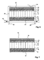
- a vacuum film 24 for example a silicone film or an elastomeric film, as in FIG Fig. 6 is shown, which is sealed at its edges by a peripheral seal 26 from the environment.
- a reusable silicone film or a silicone cover can also be used.
- a vacuum is generated under the vacuum film 24, which corresponds approximately to a 75 to 90 percent vacuum, as indicated by the arrow 28.
- a liquid resin 32 for example an epoxy resin, is introduced under the vacuum film 24, as indicated by the arrow.
- the liquid resin 32 penetrates into the fiber material 20 held on the two flat sides, flows along the flow channels F formed on the lower sides of the fiber material 20 (cf. Fig. 4 ) and impregnates the fiber material 20.
- the flow channels F cause by their course a defined flow front of the resin 32 within the fiber material 20, wherein in particular the two separating layers 16 prevent the Resin 32 penetrates into the honeycomb structures of the substrate 12. Only at the locations of the separating layer at which the openings L are formed can the liquid resin 32 also penetrate into the honeycomb structure of the carrier material 12, which results in defined resin compounds in the carrier material 12 after curing.
- vacuum is maintained below the vacuum film 24 at room temperature, corresponding to about 75 to 95 percent vacuum, which further accelerates the curing of the resin 32. This process is referred to as cold curing.
- the assembly 22 after cold curing is subjected to two post-curing steps in which the assembly 22 is first heat treated in an oven for about 2 hours at about 80 ° C. Subsequently, the assembly 22 is through-hardened over a period of about 1 hour at about 120 ° C. It should be noted, however, that the duration of the post cure depends on the resin used.
- the lightweight composite 10 is completed as shown in FIG Fig. 7 is shown, in which the fibrous material 20 embedded in the cured resin 32 forms, as a fiber composite material, in each case the cover layer 34, which is firmly connected to the carrier material 12 via the adhesive layer 18, the separating layer 16 and the adhesive layer 14.
- Table 1 two embodiments, which were manufactured according to the method described above example support material first adhesive layer Interface second adhesive layer fiber material resin first example honeycomb epoxy resin PES film epoxy resin PES fleece (polyester) epoxy Nomex second example honeycomb epoxy resin PES film epoxy resin GF-scrim (fiberglass) epoxy Nomex
- the previously described vacuum film 24 is used, under which a negative pressure is generated, which corresponds to an approximately 55 to 95 percent vacuum.
- the liquid resin 32 is passed under the vacuum film 24, wherein the negative pressure acting in the closed space 30 under the vacuum film 24 draws the resin 32 into the fiber material 20.
- a solid counter-mold is used, which is closed by means of a negative pressure corresponding to about 55 to 95 percent vacuum.
- the liquid resin 32 is injected into the mold with a slight overpressure.
- RTM process Resin Transfer Molding
- high-quality composite materials can be produced that have a smooth visible surface on both sides.
- the assembly 22 is placed between a rigid lower mold and a rigid upper mold and the two molds are closed.
- liquid resin 32 is injected into the closed mold at a pressure of about 0.2 to 8 bar.
- Table 2 below lists again the various process parameters which are set in the various processes for producing the composite material according to the invention.
- Table 2 Process parameters for the different processes process parameters attitude Temperature during vacuum infusion from room temperature to about 140 ° C Temperature at the vacuum injection from room temperature to about 140 ° C Temperature in the RTM process from room temperature to about 140 ° C Pressure during vacuum infusion corresponds to about 55 to 95% vacuum Pressure during vacuum injection corresponds to about 55 to 95% vacuum Pressure in the RTM process about 0.2 to 8 bar Filling pressure of the resin in the vacuum infusion ambient pressure Filling pressure of the resin during the vacuum injection low overpressure Filling pressure of the resin in the RTM process about 0.2 to 8 bar Temperature for curing from room temperature to 200 ° C Pressure for curing during vacuum infusion corresponds to about 75 to 95% vacuum Pressure for curing during the vacuum injection corresponds to about 75 to 95% vacuum Pressure for curing in the RTM process about 1.5 to 2.0 bar
- the separating layer 16 can optionally also be designed such that it can simultaneously serve both as a separating layer 16 and as an adhesive layer 14 to the carrier material 12 and as an adhesive layer 18 to the fiber material 20 ( see the fifth example).
- the separating layer 16 may also be formed in the form of a thin metal foil.
Description
Die Erfindung betrifft ein Leichtbau-Verbundmaterial gemäß dem Oberbegriff des Anspruchs 1. Des weiteren betrifft die Erfindung ein Verfahren gemäß dem Oberbegriff des Anspruchs 27 zur Herstellung eines derartigen Leichtbau-Verbundmaterials.The invention relates to a lightweight composite material according to the preamble of claim 1. Furthermore, the invention relates to a method according to the preamble of claim 27 for producing such a lightweight composite material.
Flächige Leichtbau-Verbundmaterialien der eingangs genannten Art sind bekannt und kommen in verschiedensten technischen Anwendungsbereichen, wie der Luft- und Raumfahrt, dem Schiffs- oder Kraftfahrzeugbau, zum Einsatz.Flat lightweight composite materials of the type mentioned are known and come in a variety of technical applications, such as aerospace, shipbuilding or motor vehicle construction, used.
Als Träger- oder Kernmaterial werden bei den bekannten Verbundmaterialien, auch Verbundwerkstoffe bzw. Materialverbund genannt, vorzugsweise flächige, vorgeformte oder verformbare Leichtbaumaterialien, beispielsweise aus Schaumstoff, aus Hölzern mit geringer Dichte oder Materialien mit Wabenstrukturen, verwendet. Um diese Leichtbaumaterialien für die Herstellung von Sandwich-Bauteilen einzusetzen, ist es üblich, an zumindest einer der Oberflächen des Trägermaterials eine Deckschicht vorzusehen. Hierdurch wird die Festigkeit des Verbundmaterials erhöht, während das Verbundmaterial selbst ein geringes Gewicht aufweist, so dass die Vorteile einer Sandwichstruktur (Verhältnis Festigkeit / Gewicht) genutzt werden können. Als Deckschichten werden beispielsweise Folien oder Faserverbundwerkstoffschichten verwendet, die an der Flachseite des Trägermaterials, beispielsweise durch Kleben, nachträglich befestigt werden.As a carrier or core material in the known composite materials, also called composites or composite material, preferably flat, preformed or deformable lightweight materials, such as foam, from low density wood or materials with honeycomb structures used. In order to use these lightweight construction materials for the production of sandwich components, it is customary to provide a cover layer on at least one of the surfaces of the carrier material. As a result, the strength of the composite material is increased, while the composite material itself has a low weight, so that the advantages of a sandwich structure (strength / weight ratio) can be used. As cover layers, for example, films or fiber composite material layers are used, which are later attached to the flat side of the carrier material, for example by gluing.
Nachteilig an den bekannten Leichtbau-Verbundmaterialien sowie den Verfahren zu deren Herstellung ist, dass bei der Herstellung der bekannten Verbundmaterialien die Ausbildung von Faserverbundwerkstoffen, welche aus in Harzen eingebettetem Fasermaterial bestehen, unmittelbar auf das Trägermaterial allenfalls sehr eingeschränkt möglich ist, wenn als Trägermaterial eine offene Schaumstoff- oder Wabenstruktur verwendet wird.A disadvantage of the known lightweight composite materials and the process for their preparation is that in the production of the known composite materials, the formation of fiber composites, which consist of embedded in resins fiber material, at most on the support material is very limited possible if the carrier material is an open Foam or honeycomb structure is used.
Die Faserverbundwerkstoffe müssen vielmehr zunächst getrennt vom Trägermaterial gefertigt werden, beispielsweise in Form sogenannter Prepregs, d.h. mit Harz preimpregnierte Gewebe oder Gelege, und können erst in einem weiteren Verfahrensschritt mit dem Trägermaterial verbunden werden. Dies ist insbesondere von Nachteil, wenn die Oberfläche des flächigen Trägermaterials nicht plan verläuft, sondern, wie beispielsweise bei Bootskörpern, einen dreidimensionalen Verlauf zeigt.Rather, the fiber composites must first be manufactured separately from the carrier material, for example in the form of so-called prepregs, i. resin-preimpregnated fabrics or scrims, and may be joined to the substrate in a further process step. This is particularly disadvantageous if the surface of the sheet-like support material is not flat, but, as for example in hulls, shows a three-dimensional course.
So sind als bekannte Verfahren für diesen Anwendungsbereich das Vakuuminfusionsverfahren, das Vakuuminjektionsverfahren, das RTM-Verfahren (RTM = Resin Transfer Moulding) sowie Abwandlungen von diesen Verfahren zu nennen, denen gemeinsam ist, unter Einsatz von Druck, d.h. Unterdruck oder Überdruck, flüssiges Harz in zum Beispiel ein Faser- oder Vliesmaterial einzubringen, das bereits auf dem mit der Deckschicht zu versehenen Trägermaterial platziert ist. Bisher werden diese bekannten Verfahren zur Herstellung von Verbundmaterialien dann eingesetzt, wenn das Träger- oder Kernmaterial an den mit der Deckschicht zu versehenen Oberflächen keine offene Struktur aufweist, oder Voll-Laminate ohne Kernmaterialien hergestellt werden sollen. Aus dem Stand der Technik sind jedoch auch Anwendungen bekannt, bei denen offene Träger- oder Kernmaterialien mit Hilfe des RTM-Verfahrens oder des Vakuuminjektionsverfahrens zur Herstellung von Verbundmaterialien mit einer Deckschicht aus in Harz eingebettetem Vlies- oder Fasermaterial beschichtet werden.Thus, as known methods for this field of application, mention may be made of the vacuum infusion method, the vacuum injection method, the RTM method (Resin Transfer Molding), as well as modifications of these methods, which are common, using pressure, i. Underpressure or overpressure, liquid resin in, for example, introduce a fiber or nonwoven material, which is already placed on the substrate to be provided with the cover layer. So far, these known methods for producing composite materials are used when the carrier or core material on the surfaces to be provided with the cover layer does not have an open structure, or full laminates are to be produced without core materials. However, there are also known in the prior art applications where open carrier or core materials are coated with a top layer of resin-embedded nonwoven or fibrous material by the RTM process or the vacuum injection process to produce composite materials.
So ist aus der
Die
In der
Die
Die
Es ist Aufgabe der Erfindung, ein Leichtbau-Verbundmaterial bzw. ein Verfahren zur Herstellung eines Leichtbau-Verbundmaterials anzugeben, bei dem bzw. durch dessen Einsatz eine verglichen mit dem Stand der Technik bessere Verteilung des Harzes im Faser- oder Vliesmaterial gegeben ist.It is an object of the invention to provide a lightweight composite material or a method for producing a lightweight composite material in which or by its use is given a comparison with the prior art better distribution of the resin in the fiber or nonwoven material.
Die Erfindung löst die Aufgabe durch ein Leichtbau-Verbundmaterial mit den Merkmalen nach Anspruch 1.The invention solves the problem by a lightweight composite material having the features of claim 1.
Der Erfindung liegt als ein wesentlicher Gedanke zugrunde, durch den Einsatz einer harzundurchlässigen Trennschicht, welche zwischen dem Trägermaterial und der Deckschicht vorgesehen wird, Verfahren, insbesondere industriell angewendete Verarbeitungsverfahren, mit denen eine Deckschicht aus einem mit Harz getränkten Faser- oder Wabenmaterial unmittelbar auf dem Träger- oder Kernmaterial erzeugt werden kann, für offenporige Trägermaterialien, wie offene Wabenstrukturen oder offenporige Schaumstoffe verwendbar zu machen.The invention is based on an essential idea, through the use of a resin-impermeable separating layer which is provided between the carrier material and the cover layer, methods, in particular industrially applied processing methods, with which a cover layer of a resin-impregnated fiber or honeycomb material directly on the support - or core material can be produced to make open porous carrier materials, such as open honeycomb structures or open-cell foam usable.
Mit Hilfe der harzundurchlässigen Trennschicht, die zwischen dem eigentlichen Trägermaterial und der Deckschicht angeordnet ist, wird bei der Herstellung des erfindungsgemäßen Verbundmaterials erreicht, dass das flüssige Harz bei der Fertigung der Deckschicht nicht in das Trägermaterial eindringen kann und dieses zumindest teilweise ausfüllt. Vielmehr kann das Harz, in dem das Faser- oder Wabenmaterial eingebettet ist, zur Ausbildung der Deckschicht unmittelbar auf dem Trägermaterial aushärten, so dass auch nichtplane Oberflächenverläufe des Trägermaterials auf einfache und elegante Weise mit einer als Verbundmaterial ausgebildeten Deckschicht versehen werden können. Es ist auch möglich, dass das an sich undurchlässige Trennmaterial Lochbohrungen aufweist, durch die das Harz an ausgewählten Stellen zur Verankerung in das Trägermaterial eindringen kann.With the aid of the resin-impermeable separating layer, which is arranged between the actual carrier material and the cover layer, it is achieved in the production of the composite material according to the invention that the liquid resin can not penetrate into the carrier material during the production of the cover layer and at least partially fills it. Rather, the resin in which the fiber or honeycomb material is embedded, to form the cover layer directly on the support material cure, so that too nichtplane surface courses of the carrier material can be provided in a simple and elegant way with a formed as a composite cover layer. It is also possible that the per se impermeable release material has holes through which the resin can penetrate at selected locations for anchoring in the carrier material.
Um eine verbesserte Verteilung des Harzes bei Anwendung der bekannten Verfahren zu ermöglichen, sind gemäß einem weiteren wesentlichen Gedanken der Erfindung im Trägermaterial und/oder in der Trennschicht und/oder in dem Faser- oder Wabenmaterial der auszubildenden Deckschicht Fliesskanäle und/oder Öffnungen vorgesehen. Auf diese Weise kann das Harz durch die Fliesskanäle und/oder Öffnungen gezielt verteilt werden, wodurch das Fließverhalten des Harzes an der Ober- und Unterseite des Faser- oder Vliesmaterials verbessert wird. Ferner füllen sich die Öffnungen, sofern vorgesehen, mit Harz, so dass nach dem Aushärten des Harzes zusätzlich Harzkanäle, die in das Kernmaterial gegebenenfalls hineinragen, ausgebildet sind, durch die dem Verbundmaterial eine zusätzliche Stabilität und Steifigkeit gegeben wird.In order to enable an improved distribution of the resin when using the known methods, flow channels and / or openings are provided according to a further essential idea of the invention in the carrier material and / or in the separating layer and / or in the fiber or honeycomb material of the cover layer to be formed. In this way, the resin can be selectively distributed by the flow channels and / or openings, whereby the flow behavior of the resin is improved at the top and bottom of the fiber or nonwoven material. Further, if provided, the openings are filled with resin, so that after hardening of the resin, additional resin channels, which possibly protrude into the core material, are formed, by which the composite material is given additional stability and rigidity.
Die Fliesskanäle und/oder Öffnungen sind hierbei vorzugsweise derart zueinander angeordnet, dass ein vorgegebenes Fliessverhalten oder eine vordefinierte Fliessfront des flüssigen Harzes im Faser- oder Wabenmaterial und/oder im Trägermaterial eingestellt werden kann.In this case, the flow channels and / or openings are preferably arranged relative to one another such that a predetermined flow behavior or a predefined flow front of the liquid resin in the fiber or honeycomb material and / or in the carrier material can be set.
Weitere Vorteile der vorliegenden Erfindung werden aus der nachfolgenden Beschreibung, den Zeichnungen sowie den Unteransprüchen ersichtlich.Further advantages of the present invention will become apparent from the following description, drawings and subclaims.
So wird bei einer besonders bevorzugten Ausführungsform des erfindungsgemäßen Verbundmaterials vorgeschlagen, ein Faser- oder Wabenmaterials, bei dem die Fliesskanäle an mindestens einer der Flachseiten des Faser- oder Wabenmaterials ausgebildet sind, oder eine Trennschicht einzusetzen, an deren dem Faser- oder Wabenmaterial zugewandten Flachseite die Fliesskanäle ausgebildet sind. Hierdurch wird erreicht, dass sich das flüssige Harz zwischen den aneinander anliegenden Flachseiten der Trennschicht und des Faser- oder Wabenmaterials besonders gleichmäßig verteilt und das Harz nach dem Aushärten eine besonders gute Verbindung zwischen dem Faser- oder Wabenmaterial und der Trennschicht bildet.Thus, in a particularly preferred embodiment of the composite material according to the invention, it is proposed to use a fibrous or honeycomb material in which the flow channels are formed on at least one of the flat sides of the fibrous or honeycomb material, or to use a separating layer at whose flat side facing the fibrous or honeycomb material Fliesskanäle are formed. This ensures that the liquid resin particularly evenly distributed between the abutting flat sides of the release layer and the fiber or honeycomb material and the resin forms a particularly good bond between the fiber or honeycomb material and the release layer after curing.
Wird ein fasermaterial verwendet, sind die Fliesskanäle in die betreffende Flachseite vorzugsweise eingeprägt. Wird dagegen ein Wabenmaterial für die Deckschicht verwendet, sind die Fliesskanäle an der betreffenden Flachseite des Wabenmaterials ausgeformt.If a fiber material is used, the flow channels are preferably embossed into the relevant flat side. In contrast, if a honeycomb material is used for the cover layer, the flow channels are formed on the relevant flat side of the honeycomb material.
Um eine möglichst gleichmäßige Verteilung des flüssigen Harzes sicherzustellen, verlaufen die Fliesskanäle vorzugsweise in einer wabenartigen Struktur, wodurch das flüssige Harz gezielt umgeleitet werden kann. Die wabenartige Struktur kann hierbei gegebenenfalls auch unregelmäßig entsprechend einem vorgegebenen Muster verlaufen, so dass ein definiertes Fliessverhalten des flüssigen Harzes gezielt vorgegeben werden kann.In order to ensure the most uniform possible distribution of the liquid resin, the flow channels preferably run in a honeycomb-like structure, whereby the liquid resin can be specifically diverted. If appropriate, the honeycomb-like structure may also run irregularly in accordance with a predetermined pattern, so that a defined flow behavior of the liquid resin can be predetermined in a targeted manner.
Des weiteren wird vorgeschlagen, in der Oberfläche des Trägermaterials und/oder der Oberfläche der Trennschicht definierte Öffnungen, vorzugsweise in Form von Lochbohrungen vorzusehen, die normal zur Flachseite des Trägermaterials oder der Trennschicht verlaufen. Hierdurch kann das Harz durch die Öffnungen in das Trägermaterial eindringen, wodurch das Fließverhalten des Harzes an der Ober- und Unterseite des Faser- oder Wabenmaterials verbessert wird. Ferner füllen sich die Öffnungen mit Harz, so dass nach dem Aushärten des Harzes zusätzlich Harzkanäle durch das Kernmaterial gebildet sind, die dem fertigen Verbundmaterial eine erhöhte Stabilität und Steifigkeit verleihen.Furthermore, it is proposed to provide openings defined in the surface of the carrier material and / or the surface of the separating layer, preferably in the form of perforations, which run normal to the flat side of the carrier material or of the separating layer. This allows the resin to penetrate through the openings in the carrier material, whereby the flow behavior of the resin is improved at the top and bottom of the fiber or honeycomb material. Furthermore, the openings fill with resin, so that after hardening of the resin in addition resin channels are formed by the core material, which give the finished composite material increased stability and rigidity.
Bei einer weiteren bevorzugten Ausführungsform des erfindungsgemäßen Verbundmaterials wird vorgeschlagen, ein flaches Trägermaterial einzusetzen, dessen beide Flachseiten als Oberflächen in erfindungsgemäßer Weise mit einer Trennschicht und einer Deckschicht versehen werden. Hierdurch wird erreicht, dass das Trägermaterial von beiden Flachseiten her verschlossen ist und als Sandwich-Material ausgebildet wird. Es ist jedoch auch denkbar, nur eine der beiden Flachseiten mit dem erfindungsgemäßen Schichtaufbau zu versehen, während die andere Flachseite in herkömmlicher Weise versiegelt ist, beispielsweise durch Verwendung einer aufgeklebten Folie.In a further preferred embodiment of the composite material according to the invention, it is proposed to use a flat carrier material, the two flat sides of which are provided as surfaces in the manner according to the invention with a separating layer and a covering layer. This ensures that the carrier material is closed by both flat sides and is formed as a sandwich material. However, it is also conceivable to provide only one of the two flat sides with the layer structure according to the invention, while the other flat side is sealed in a conventional manner, for example by using a glued foil.
Die Trennschicht ist vorzugsweise aus einer Polymerfolie gebildet, welche auf die Oberfläche des Trägermaterials aufgebracht ist. Als Folie eignet sich insbesondere eine Folie aus einem thermoplastischen Kunststoff, da diese einfach zu verarbeiten ist und mit vergleichsweise geringem Aufwand an den Oberflächenverlauf angepaßt werden kann.The separating layer is preferably formed from a polymer film which is applied to the surface of the carrier material. As a film is particularly suitable a film of a thermoplastic material, since it is easy to work with and can be adapted to the surface course with relatively little effort.
Um eine besonders gute Verbindung der Deckschicht mit der Trennschicht zu erreichen, wird bei einer besonders bevorzugten Ausführungsform des erfindungsgemäßen Verbundmaterials vorgeschlagen, als Trennschicht ein Gewebe, ein Gelege, ein Geflecht, ein Gewirk, ein Gestrick oder ein Vlies einzusetzen. Die Dicke der Trennschicht ist hierbei so bemessen, dass das flüssige Harz beim Erzeugen der Deckschicht zwar gegebenenfalls in die Trennschicht eindringt, durch diese jedoch nicht bis zum Trägermaterial gelangt. Auf diese Weise ist die Trennschicht durch das Harz mit dem Fasermaterial der Deckschicht verbunden, sobald das Harz ausgehärtet ist. Hierdurch ergibt sich eine besonders gute Verbindung der Deckschicht mit der Trennschicht.In order to achieve a particularly good connection of the cover layer with the release layer, in a particularly preferred embodiment of the composite material according to the invention, it is proposed to use as a release layer a woven fabric, a scrim, a braid, a knitted fabric, a knitted fabric or a fleece. The thickness of the separating layer is in this case dimensioned such that the liquid resin optionally penetrates into the separating layer during the production of the covering layer, but does not pass through the latter to the carrier material. In this way, the release layer is through the resin with the fiber material of the cover layer connected as soon as the resin has hardened. This results in a particularly good connection of the cover layer with the release layer.
Das Gewebe, Gelege, Geflecht, Gewirk, Gestrick oder Vlies ist vorzugsweise aus einem thermoplastischen Kunststoff oder einem Fasermaterial gefertigt ist, wobei das Kunststoffoder Fasermaterial bevorzugt zumindest annähernd dieselben physikalischen Eigenschaften hinsichtlich des Elastizitätsmoduls oder der temperaturabhängigen Ausdehnungskoeffizienten hat, wie das Fasermaterial der Deckschicht.The woven fabric, scrim, braid, knitted fabric or nonwoven fabric is preferably made of a thermoplastic material or a fiber material, wherein the plastic or fiber material preferably has at least approximately the same physical properties with regard to the modulus of elasticity or the temperature-dependent expansion coefficients as the fiber material of the cover layer.
Gegebenenfalls ist es auch denkbar, die Trennschicht aus einem Material auszubilden, das sich nach dem Aushärten des Harzes ganz oder teilweise aufgelöst hat.Optionally, it is also conceivable to form the release layer of a material which has completely or partially dissolved after the curing of the resin.
Des weiteren ist es denkbar, sowohl die als Folie ausgebildete Trennschicht als auch die als Gewebe, Gelege, Geflecht, Gewirk, Gestrick oder Vlies ausgebildete Trennschicht aus Kunststoffen zu fertigen. Als Material hierfür eignen sich alle zu Folien oder Fasern zu verarbeitende Polymere. Besonders bevorzugt sind als Polymere Polyester, Polyethylen, Polyvinylchlorid, Polypropylen, Polyamid, Polycarbonat, Polyacryl, Polyacrylnitril, Polytetrafluorethylen oder Gemische aus diesen Kunststoffen.Furthermore, it is conceivable to manufacture both the release layer in the form of a film and the separating layer of plastics in the form of a woven fabric, scrim, braid, knitted fabric, knitted fabric or nonwoven. Suitable materials for this are all polymers to be processed into films or fibers. Particularly preferred polymers are polyesters, polyethylene, polyvinyl chloride, polypropylene, polyamide, polycarbonate, polyacrylic, polyacrylonitrile, polytetrafluoroethylene or mixtures of these plastics.
Bei einer alternativen Ausführungsform dient als Trennschicht eine Schaumstofflage oder eine Schaumstofffolie. Auch hier besteht, ähnlich wie bei der glatten Folie, der Vorteil, dass sich die Schaumstofflage oder Schaumstofffolie an die Oberfläche des Trägermaterials gleichmäßig anschmiegen kann. Des weiteren besteht darüber hinaus der Vorteil, dass die Schaumstofflage oder Schaumstofffolie zu einer erhöhten Wärmedämmung beim erfindungsgemäßen Verbundmaterial führt. Das Schaumstoffmaterial der Schaumstofflage oder der Schaumstofffolie kann dabei geschlossenporig oder auch offenporig ausgebildet sein.In an alternative embodiment serves as a release layer, a foam layer or a foam sheet. Again, there is, similar to the smooth film, the advantage that the foam layer or foam sheet can evenly cling to the surface of the substrate. Furthermore, there is the additional advantage that the foam layer or foam film leads to increased thermal insulation in the composite material according to the invention. The foam material of the foam layer or the foam film can be closed-pored or open-pored.
Die Schaumstofflage oder die Schaumstofffolie kann aus allen zu Schäumen zu verarbeitenden Materialien gefertigt sein. Bevorzug ist sie aus Polyurethan, linearem oder vernetztem Polyvinylchlorid, Polyetherimid, Polymethacrylimid, einem Phenolharz, einem Epoxidharz oder aus einem Gemisch von zumindest zwei der zuvor genannten Kunststoffe gefertigt.The foam layer or the foam film can be made of all materials to be processed into foams. Preferably it is made of polyurethane, linear or crosslinked polyvinyl chloride, polyetherimide, polymethacrylimide, a phenolic resin, an epoxy resin or a mixture of at least two of the aforementioned plastics.
Des weiteren wird bei einer weiteren Ausführungsform des erfindungsgemäßen Verbundmaterials vorgeschlagen, als Trennschicht eine Metallfolie, vorzugsweise aus Aluminium, Stahl, Bronze oder Kupfer, einzusetzen. Auch eine dünne Bleifolie ist als Trennschicht geeignet. Durch den Einsatz einer Metallfolie als Trennschicht wird erreicht, dass das erfindungsgemäße Verbundmaterial eine abschirmende Wirkung beispielsweise gegenüber elektromagnetischen Wellen aufweist, so dass die Trennschicht eine Doppelfunktion erfüllt, nämlich einerseits ihre erfindungsgemäße Verwendung, ein Eindringen von flüssigem Harz in die das Trägermaterial zu verhindern, und andererseits ihre Wirkung als Abschirmung.Furthermore, in a further embodiment of the composite material according to the invention, it is proposed to use a metal foil, preferably of aluminum, steel, bronze or copper, as the separating layer. Even a thin lead foil is suitable as a release layer. The use of a metal foil as a separating layer ensures that the composite material according to the invention has a shielding effect, for example against electromagnetic waves, so that the separating layer fulfills a dual function, namely its use according to the invention, penetration of liquid resin into which the carrier material is prevented, and on the other hand its effect as a shield.
Um die Trennschicht am Trägermaterial zu befestigen, wird vorgeschlagen, zwischen der Trennschicht und dem Trägermaterial eine erste Klebeschicht vorzusehen. Die Klebeschicht wird beispielsweise in Form einer Klebefolie auf dem Trägermaterial aufgebracht. Anschließend wird die Trennschicht, beispielsweise ein Trenngewebe, auf die Klebefolie aufgelegt und mit dieser verklebt.In order to secure the release layer to the carrier material, it is proposed to provide a first adhesive layer between the release layer and the carrier material. The adhesive layer is applied for example in the form of an adhesive film on the carrier material. Subsequently, the release layer, for example, a release fabric, placed on the adhesive film and glued to it.
Des weiteren wird vorgeschlagen, zusätzlich oder alternativ auch zwischen der Trennschicht und der Deckschicht eine Klebeschicht vorzusehen. Mit dieser Klebeschicht kann das Fasermaterial, mit dem die Deckschicht gebildet werden soll, vor dem Aufbringen des flüssigen Harzes an der Trennschicht in einer definierten Lage gehalten werden. Außerdem dient diese Klebeschicht als zusätzliche Verklebungsmöglichkeit zwischen Trennschicht und Deckschicht.Furthermore, it is proposed to additionally or alternatively also provide an adhesive layer between the release layer and the cover layer. With this adhesive layer, the fiber material with which the cover layer is to be formed can be kept in a defined position prior to the application of the liquid resin to the release layer. In addition, this adhesive layer serves as additional bonding possibility between release layer and cover layer.
Die Klebeschicht bzw. die Klebeschichten sind vorzugsweise als ein Klebefilm auf Basis eines Epoxidharzes, eines Polyesterharzes, eines Phenolharzes, eines Vinylesterharzes, eines Acrylharzes, eines Acrylatklebstoffes oder eines Silans ausgebildet. Es können jedoch auch Klebefilme eingesetzt werden, die auf Basis eines Gemisches von mindestens zwei der zuvor genannten Harze gebildet sind.The adhesive layer or layers are preferably formed as an adhesive film based on an epoxy resin, a polyester resin, a phenol resin, a vinyl ester resin, an acrylic resin, an acrylate adhesive or a silane. However, it is also possible to use adhesive films which are formed on the basis of a mixture of at least two of the aforementioned resins.
Um den Herstellungsprozeß zu vereinfachen, wird ferner vorgeschlagen, die Klebeschicht bzw. die Klebeschichten bereits vorab auf der Trennschicht vorzusehen, da auf diese Weise ein getrenntes Aufbringen der Klebeschichten von der Trennschicht entfallen kann.In order to simplify the manufacturing process, it is further proposed to provide the adhesive layer or the adhesive layers in advance on the release layer, since in this way a separate application of the adhesive layers from the release layer can be dispensed with.
So wird beispielsweise vorgeschlagen, wenn als Trennschicht eine Kunststoff- oder Metallfolie zum Einsatz kommt, die Folie an der Vorder- und gegebenenfalls Rückseite vorab mit einem Klebefilm zu versehen.Thus, it is proposed, for example, if a plastic or metal foil is used as the release layer, the foil on the front side and, if appropriate, back side must be provided in advance with an adhesive film.
Als Fasermaterial für die Deckschicht dient vorzugsweise ein Gewebe, ein Gelege, ein Geflecht, ein Gewirk, ein Gestrick, ein Vlies oder ein Hybridmaterial, da diese Art Fasermaterial vom flüssigen Harz gleichmäßig durchtränkt werden kann und nach dem Aushärten des Harzes der Deckschicht, je nach verwendeter Systemkombination, eine hohe mechanische Festigkeit bei gleichzeitig hervorragenden elastischen Eigenschaften verleiht.As the fibrous material for the cover layer is preferably a woven fabric, a scrim, a braid, a knitted fabric, a knit fabric, a nonwoven or a hybrid material, since this type of fiber material can be uniformly soaked by the liquid resin and after curing of the resin of the cover layer, depending on used system combination, a high mechanical strength and at the same time gives excellent elastic properties.
Um die mechanischen Eigenschaften des Fasermaterials gezielt zu beeinflussen, werden für diese Arten von Fasermaterial vorzugsweise Materialien verwendet, die Glasfasern, Carbon-Fasern, Aramid-Fasern, Keramik-Fasern, Metall-Fasern und/oder Metalldrähte aufweisen. Alternativ werden für diese Arten von Fasermaterial auch Materialien eingesetzt, welche auf thermoplastischen Kunststoffen oder Elastomeren basieren.In order to influence the mechanical properties of the fiber material in a targeted manner, materials which comprise glass fibers, carbon fibers, aramid fibers, ceramic fibers, metal fibers and / or metal wires are preferably used for these types of fiber material. Alternatively, materials based on thermoplastics or elastomers are also used for these types of fiber material.
Als Harzmaterial, in dem das Fasermaterial eingebettet ist, wird vorzugsweise ein Epoxidharz, ein Polyesterharz, ein Phenolharz, ein Vinylesterharz, ein Acrylharz, ein Silan oder ein Gemisch mindestens zwei dieser Harze verwendet, da diese Harze gut verarbeitbar sind und vergleichsweise schnell aushärten.As the resin material in which the fibrous material is embedded, it is preferable to use an epoxy resin, a polyester resin, a phenol resin, a vinyl ester resin, an acrylic resin, a silane or a mixture of at least two of these resins because these resins are easy to process and cure relatively quickly.
Bei einer besonders bevorzugten Ausführungsform des erfindungsgemäßen Verbundmaterials weist das Trägermaterial eine vorzugsweise gleichmäßige, gegebenenfalls auch harzgetränkte Wabenstruktur auf. Durch die gleichmäßige Wabenstruktur wird eine besonders hohe mechanische Festigkeit insbesondere in Längsrichtung der einzelnen Waben bei geringem spezifischen Gewicht erreicht. Die Waben verlaufen hierbei vorzugsweise mit ihren Längsrichtungen etwa lotrecht zur Trenn- und Deckschicht.In a particularly preferred embodiment of the composite material according to the invention, the support material has a preferably uniform, possibly also resin-impregnated honeycomb structure. Due to the uniform honeycomb structure, a particularly high mechanical strength is achieved, in particular in the longitudinal direction of the individual honeycombs with a low specific weight. The honeycombs preferably run with their longitudinal directions approximately perpendicular to the release and cover layer.
Die Wabenstruktur kann aus Metall, vorzugsweise aus Aluminium, gebildet sein. Für Einsatzzwecke, bei denen das Gewicht des Verbundmaterials im Vordergrund steht, werden Wabenstrukturen aus Papier oder Pappe als Trägermaterial vorgeschlagen. Diese aus Papier oder Pappe gebildeten Wabenstrukturen können zusätzlich mit Fasern verstärkt sein. So werden besonders bevorzugt Wabenstrukturen aus Papier oder Pappe für das erfindungsgemäße Verbundmaterial eingesetzt, bei denen das Papier- oder Pappmaterial mit Aramid-Fasern, insbesondere Nomex®-Fasern oder Kevlar®-Fasern, Polyesterfasern, PVC-Fasern Polyacrylfasern, Polypropylenfasern oder einem Gemisch aus mindestens zwei dieser Faserarten ergänzt ist. Die Wabenstrukturen können gegebenenfalls zusätzlich mit Harz getränkt sein. Des weiteren kann die Wabenstruktur aus einem Kunststoffmaterial gefertigt sein. Ferner ist es denkbar, dass in die Wabenstruktur ein Füllmaterial, beispielsweise Mikroballons, gefüllt ist.The honeycomb structure may be formed of metal, preferably of aluminum. For applications in which the weight of the composite material is in the foreground, honeycomb structures of paper or cardboard are proposed as a carrier material. These honeycomb structures formed of paper or paperboard can additionally be reinforced with fibers. Thus honeycomb structures made of paper or cardboard are particularly preferred the composite material according to the invention is used, in which the paper or cardboard material is supplemented with aramid fibers, in particular Nomex® fibers or Kevlar® fibers, polyester fibers, PVC fibers, polyacrylic fibers, polypropylene fibers or a mixture of at least two of these types of fibers. The honeycomb structures may optionally be additionally impregnated with resin. Furthermore, the honeycomb structure may be made of a plastic material. Furthermore, it is conceivable for a filling material, for example microballoons, to be filled in the honeycomb structure.
Zusätzlich wird vorgeschlagen, anstelle einer Wabenstruktur als Trägermaterial ein vorzugsweise offenporiges Schaumstoffmaterial einzusetzen. Die Verwendung von Schaumstoffmaterial als Trägermaterial ist besonders dann von Vorteil, wenn das Verbundmaterial eine hohe Wärmedämmwirkung aufweisen soll. Das Schaumstoffmaterial ist hierbei vorzugsweise aus Polyurethan, linearem oder vernetztem Polyvinylchlorid, Polyetherimid, Polymethacrylimid, Phenolharz, Epoxidharz oder Gemischen derselben gefertigt. Es ist jedoch auch denkbar, aus Metall aufgeschäumte Schaumstoffmaterialien zu verwenden.In addition, it is proposed to use a preferably open-cell foam material instead of a honeycomb structure as the carrier material. The use of foam material as a carrier material is particularly advantageous if the composite material should have a high thermal insulation effect. The foam material here is preferably made of polyurethane, linear or crosslinked polyvinyl chloride, polyetherimide, polymethacrylimide, phenolic resin, epoxy resin or mixtures thereof. However, it is also conceivable to use foamed metal foam materials.
Ferner wird ein erfindungsgemäßes Leichtbau-Verbundmaterial vorgeschlagen, bei dem das Trägermaterial aus Balsa-Holz gefertigt ist.Furthermore, a lightweight composite material according to the invention is proposed, in which the carrier material is made of balsa wood.
Gemäß einem zweiten Aspekt betrifft die Erfindung ein Verfahren zur Herstellung eines Leichtbau-Verbundmaterials, insbesondere ein Verfahren zur Herstellung eines Leichtbau-Verbundmaterials, wie es zuvor beschrieben worden ist. So soll das mit dem erfindungsgemäßen Verfahren herzustellende Verbundmaterial ein Leichtbau-Trägermaterial, eine auf mindestens einer der Oberflächen des Trägermaterials vorgesehene Deckschicht aus einem in einem Harzmaterial eingebetteten Faser- oder Wabenmaterial und eine zwischen dem Trägermaterial und der Deckschicht angeordnete harzundurchlässige Trennschicht aufweisen.According to a second aspect, the invention relates to a method for producing a lightweight composite material, in particular a method for producing a lightweight composite material, as has been described above. Thus, the composite material to be produced by the method according to the invention is intended to comprise a lightweight support material, a cover layer made of a fibrous or honeycomb material embedded in a resin material on at least one of the surfaces of the support material, and a resin-impermeable release layer disposed between the support material and the cover layer.
Zur Herstellung dieses Verbundmaterials wird zunächst auf die zu beschichtende Oberfläche des Trägermaterials die Trennschicht aufgebracht. Anschließend wird auf die Trennschicht das Faser- oder Wabenmaterial der Deckschicht aufgebracht. Das Faser- oder Wabenmaterial wird anschließend mit einem flüssigen Harz getränkt, das zur Bildung der Deckschicht auf der Trennschicht aushärtet, wobei die am Faser- oder Wabenmaterial, an der Trennschicht und/oder dem Trägermaterial ausgebildeten Fliesskanäle und/oder Öffnungen eine gleichmäßige Verteilung des Harzes bewirken.To produce this composite material, the release layer is first applied to the surface of the support material to be coated. Subsequently, the fiber or honeycomb material of the cover layer is applied to the release layer. The fiber or honeycomb material is then impregnated with a liquid resin, which is used to form the Curing layer on the release layer, wherein the formed on the fiber or honeycomb material, on the release layer and / or the carrier material flow channels and / or openings cause a uniform distribution of the resin.
Zum Tränken des Fasermaterials mit dem flüssigen Harz wird bei einer besonders bevorzugten Ausführungsvariante die sich ergebende Anordnung aus Trägermaterial, Trennschicht und Fasermaterial in einen abgeschlossenen Raum eingesetzt. In den abgeschlossenen Raum wird das flüssige Harz geleitet, das in das auf der Trennschicht aufgebrachte Fasermaterial eindringt. Die Trennschicht verhindert dabei, dass das flüssige Harz in das Trägermaterial eindringt. Sobald das flüssige Harz zumindest soweit ausgehärtet ist, dass sich die Gestalt der Deckschicht, die aus dem in dem ausgehärteten Harz eingebetteten Faser- oder Vliesmaterial gebildet ist, nicht mehr ändert, kann das Verbundmaterial dem abgeschlossenen Raum entnommen werden.For impregnating the fiber material with the liquid resin, the resulting arrangement of carrier material, separating layer and fiber material is used in a closed space in a particularly preferred embodiment variant. In the closed space, the liquid resin is passed, which penetrates into the fiber material applied to the release layer. The separating layer prevents the liquid resin from penetrating into the carrier material. Once the liquid resin has cured at least to the extent that the shape of the cover layer, which is formed from the fiber or nonwoven material embedded in the cured resin, no longer changes, the composite material can be removed from the enclosed space.
Um das Eindringen des flüssigen Harzes in das Fasermaterial zu beschleunigen, wird bei einer besonders bevorzugten Variante des erfindungsgemäßen Verfahrens vorgeschlagen, das flüssige Harz unter Druck in den abgeschlossenen Raum einzubringen. Das flüssige Harz kann hierzu mit einem Druck in einem Bereich von etwa 0,2 bis 8 bar in den abgeschlossenen Raum gefördert werden. Der Druck kann jedoch auch höher sein, wenn die Form dem Förderdruck standhält.In order to accelerate the penetration of the liquid resin into the fiber material, it is proposed in a particularly preferred variant of the method according to the invention to introduce the liquid resin under pressure into the enclosed space. For this purpose, the liquid resin can be conveyed into the closed space at a pressure in the range of about 0.2 to 8 bar. However, the pressure may be higher if the mold withstands the delivery pressure.
Der abgeschlossene Raum wird bei einer Variante des Verfahrens, insbesondere wenn das Verfahren zur Massenfertigung von Verbundmaterialien eingesetzt werden soll, durch eine feste Form aus mindestens zwei Formteilen gebildet, deren Innenkonturen der späteren Außenkontur des fertigen Bauteils entsprechen. Die Anordnung aus Trägermaterial, Trennschicht und Fasermaterial wird in die offene Form eingelegt, die Form anschließend geschlossen und das flüssige Harz unter Druck in die Form eingefüllt. Nach dem Aushärten des Harzes entspricht die Außenkontur des Verbundmaterials der durch die Form vorgegebenen Gestalt. Zum Aushärten des Harzes wird die Form zumindest abschnittsweise erwärmt.In a variant of the method, in particular if the method is to be used for the mass production of composite materials, the enclosed space is formed by a fixed shape from at least two molded parts whose inner contours correspond to the later outer contour of the finished component. The arrangement of carrier material, release layer and fiber material is placed in the open mold, the mold is then closed and filled the liquid resin under pressure into the mold. After curing of the resin, the outer contour of the composite material corresponds to the shape predetermined by the mold. To harden the resin, the mold is heated at least in sections.
Alternativ ist es auch möglich, in der geschlossenen Form einen Unterdruck zu erzeugen, der vorzugsweise einem etwa 55- bis 95-prozentigen Vakuum entspricht. Anschließend wird das flüssige Harz mit geringem Überdruck in die geschlossene Form geleitet.Alternatively, it is also possible to generate a negative pressure in the closed mold, which preferably corresponds to an approximately 55 to 95 percent vacuum. Subsequently, the liquid resin is passed with a slight overpressure in the closed mold.
Bei einer alternativen Variante des erfindungsgemäßen Verfahrens wird der abgeschlossene Raum durch eine Folie gebildet, unter der die Anordnung positioniert wird. Die Luft in dem abgeschlossenen Raum unter der Folie, in dem sich die Anordnung befindet, wird anschließend abgepumpt, so dass unter der Folie ein Unterdruck erzeugt wird. Dieser entspricht vorzugsweise einem etwa 55- bis 95-prozentigen Vakuum. Anschließend wird das Harz mit Umgebungsdruck unter die Folie geleitet.In an alternative variant of the method according to the invention, the enclosed space is formed by a film under which the arrangement is positioned. The air in the enclosed space under the film in which the arrangement is located is then pumped off, so that under the film, a negative pressure is generated. This preferably corresponds to an approximately 55 to 95 percent vacuum. Subsequently, the resin is passed under ambient pressure under the film.
Alternativ ist es auch möglich, die komplette Anordnung aus Trägermaterial, Trennschicht und Fasermaterial zum Tränken des Fasermaterials mit flüssigem Harz in ein Harzbad zumindest abschnittsweise einzutauchen, sofern das Trägermaterial, beispielsweise eine Wabenstruktur, an den Stellen, an den es in das Harzbad eingetaucht wird, nach außen hin durch die Trennschicht abgedeckt ist.Alternatively, it is also possible to immerse the complete arrangement of carrier material, separating layer and fiber material for impregnating the fiber material with liquid resin in a resin bath at least in sections, provided that the carrier material, for example a honeycomb structure, at the points where it is immersed in the resin bath, is covered by the separating layer to the outside.
Haftet die Trennschicht nicht in ausreichendem Maß an der Oberfläche des Trägermaterials an, oder ist die Trennschicht mit keiner zusätzlichen Klebeschicht versehen, wird ferner vorgeschlagen, vor dem Aufbringen der Trennschicht auf die Flachseite des Trägermaterials eine Klebeschicht aufzubringen, auf welche wiederum die Trennschicht aufgelegt wird.If the separating layer does not adhere sufficiently to the surface of the carrier material, or if the separating layer is not provided with an additional adhesive layer, it is also proposed to apply an adhesive layer to the flat side of the carrier material prior to the application of the separating layer to which the separating layer is in turn applied.
In entsprechender Weise wird bei einer weiteren Variante des erfindungsgemäßen Verfahrens vorgeschlagen, vor dem Aufbringen des die Deckschicht bildenden Fasermaterials auf die Trennschicht eine Klebeschicht aufzubringen, auf welche wiederum das Fasermaterial aufgebracht wird.In a corresponding manner, in a further variant of the method according to the invention, it is proposed to apply an adhesive layer to the release layer before applying the covering material to the release layer, to which in turn the fiber material is applied.
Um eine möglichst gleichmäßige und schnelle Aushärtung des flüssigen Harzes zu erreichen, wird bei einer besonders bevorzugten Variante des erfindungsgemäßen Verfahrens der abgeschlossene Raum unter Unter- oder Überdruck gesetzt. Dies ist einerseits möglich in dem bei Verwendung einer geschlossenen Form in der Form ein entsprechender Überdruck erzeugt wird, der beispielsweise bei etwa 2 bar liegt. Wird dagegen eine Vakuumfolie verwendet, wird der Unterdruck unter der Folie über einen vorgegebenen Zeitraum aufrechterhalten.In order to achieve the most uniform and rapid curing of the liquid resin, in a particularly preferred variant of the process according to the invention the closed space is placed under reduced or elevated pressure. This is possible, on the one hand, in which, when a closed mold is used, a corresponding overpressure is generated in the mold, which is for example about 2 bar. Becomes on the other hand uses a vacuum film, the negative pressure is maintained under the film over a predetermined period.
Um das bereits ausgehärtete Harz nachzuhärten, wird ferner vorgeschlagen, die Anordnung aus Trägermaterial, Trennschicht und Fasermaterial nach dem Aushärten des Harzes einer Wärmebehandlung zu unterziehen, bei der die Anordnung über einen vorgegebenen Zeitraum auf eine Temperatur in einem Bereich von etwa 50°C bis 200°C erwärmt wird. Hierdurch wird das Aushärten des Harzes weiter beschleunigt. In Abhängigkeit von dem jeweils verwendeten Harz kann es durch die zusätzliche Wärmebehandlung noch zu einer weiteren Vernetzung des Harzes kommen, wodurch die Festigkeit des als Deckschicht dienenden Faserverbundmaterials weiter erhöht wird.In order to postcure the already cured resin, it is further proposed to subject the assembly of carrier material, release layer and fiber material after curing of the resin to a heat treatment, wherein the arrangement over a predetermined period of time to a temperature in a range of about 50 ° C to 200 ° C is heated. As a result, the curing of the resin is further accelerated. Depending on the particular resin used, the additional heat treatment may result in further crosslinking of the resin, which further increases the strength of the fiber composite material used as cover layer.
Um das Nachhärten gezielt auf das jeweilige Harz einzustellen, wird ferner, je nach verwendeter Materialkombination, vorgeschlagen, die Wärmebehandlung in zwei Schritten zu vollziehen, wobei die Anordnung in dem ersten Wärmebehandlungsschritt über einen vorgegebenen ersten Zeitraum auf eine Temperatur von etwa 50°C bis 90°C und in dem zweiten Wärmebehandlungsschritt über einen vorgegebenen zweiten Zeitraum auf eine Temperatur von etwa 100°C bis 200°C erwärmt wird.In order to adjust the postcuring specifically to the particular resin, it is further proposed, depending on the combination of materials used, to carry out the heat treatment in two steps, wherein the arrangement in the first heat treatment step over a predetermined first period to a temperature of about 50 ° C to 90 ° C and in the second heat treatment step over a predetermined second period of time to a temperature of about 100 ° C to 200 ° C is heated.
Nachfolgend wird der Erfindung anhand einer Verfahrensvariante unter Bezugnahme auf die beigefügte Zeichnung näher erläutert. Darin zeigt:
- Fig. 1
- einen ersten Schritt des erfindungsgemäßen Verfahrens in schematischer, geschnittener Darstellung, in dem auf ein Trägermaterial beidseitig Klebefilme aufgebracht werden;
- Fig. 2
- einen zweiten Schritt des erfindungsgemäßen Verfahrens in schematischer, geschnittener Darstellung, in dem auf die Klebefilme beidseitig eine Trennfolie aufgebracht wird;
- Fig. 3
- einen dritten Schritt des erfindungsgemäßen Verfahrens in schematischer, geschnittener Darstellung, in dem auf jede Trennfolie ein zweiter Klebefilm aufgebracht wird;
- Fig. 4
- eine Unteransicht eines Fasermaterials in Form eines Polyestervlieses, an dessen Unterseite wabenförmige Fliesskanäle ausgebildet sind;
- Fig. 5
- einen vierten Schritt des erfindungsgemäßen Verfahrens in schematischer, geschnittener Darstellung, in dem auf die beiden Klebefilme jeweils das Fasermaterial aufgebracht wird;
- Fig. 6
- einen fünften Schritt des erfindungsgemäßen Verfahrens in schematischer, geschnittener Darstellung, in dem die Anordnung aus Trägermaterial, Klebeschichten, Trennfolien und Fasermaterial unter eine Vakuumfolie gelegt und ein flüssiges Harz eingefüllt wird; und
- Fig. 7
- eine geschnittene Darstellung des fertigen Verbundmaterials.
- Fig. 1
- a first step of the method according to the invention in a schematic, sectional representation, in which adhesive films are applied on both sides of a carrier material;
- Fig. 2
- a second step of the method according to the invention in a schematic, sectional view, in which a release film is applied to the adhesive films on both sides;
- Fig. 3
- a third step of the method according to the invention in a schematic, sectional view, in which a second adhesive film is applied to each release film;
- Fig. 4
- a bottom view of a fiber material in the form of a polyester fleece, formed on the underside honeycomb flow channels;
- Fig. 5
- a fourth step of the method according to the invention in a schematic, sectional view, in which the respective fiber material is applied to the two adhesive films;
- Fig. 6
- a fifth step of the method according to the invention in a schematic, sectional view, in which the arrangement of carrier material, adhesive layers, release films and fiber material placed under a vacuum foil and a liquid resin is filled; and
- Fig. 7
- a sectional view of the finished composite material.
In den
In dem in
In einem zweiten Verfahrensschritt, der in
In einem dritten Verfahrensschritt, der in
In
Die so gebildete Anordnung 22 aus Trägermaterial 12, Klebeschichten 14, Trennschichten 16, Klebeschichten 18 und Fasermaterial 20 wird anschließend von einer Vakuumfolie 24, beispielsweise einer Silikonfolie oder einer Elastomerfolie, bedeckt, wie in
Das flüssige Harz 32 dringt in das an den beiden Flachseiten gehaltene Fasermaterial 20 ein, strömt entlang der an den Unterseiten des Fasermaterials 20 jeweils ausgebildeten Fliesskanäle F (vgl.
Sobald das flüssige Harz 32 ausgehärtet ist, wird unter der Vakuumfolie 24 bei Raumtemperatur ein Unterdruck aufrechterhalten, der einem etwa 75- bis 95-prozentigem Vakuum entspricht, durch den das Aushärten des Harzes 32 weiter beschleunigt wird. Dieser Vorgang wird als Kaltaushärten bezeichnet.Once the
Nach einem vorgegebenen Zeitraum von beispielsweise 12 Stunden wird die Anordnung 22 nach dem Kaltaushärten zwei Nachhärteschritten unterzogen, in denen die Anordnung 22 zunächst in einem Ofen über einen Zeitraum von 2 Stunden bei etwa 80°C warmbehandelt wird. Anschließend wird die Anordnung 22 über einen Zeitraum von etwa 1 Stunde bei etwa 120°C durchgehärtet. Es ist jedoch zu bemerken, dass die Dauer der Nachhärtung vom verwendeten Harz abhängig ist.After a predetermined period of, for example, 12 hours, the
Nach dem Durchhärten ist das Leichtbau-Verbundmaterial 10 fertiggestellt, wie es in
In der nachfolgenden Tabelle 1 sind die verwendeten Materialien nochmals aufgelistet, wobei auch eine abgewandelte Ausführungsform aufgeführt ist.
Die beiden beschriebenen Ausführungsbeispiele stellen nur zwei Varianten einer Vielzahl von möglichen Kombinationen der verschiedenen Materialien dar. Des weiteren kann zwischen den verschiedenen Verfahren, nämlich dem Vakuuminfusionsverfahren, dem Vakuuminjektionsverfahren oder dem RTM-Verfahren (RTM = Resin Transfer Moulding) unterschieden werden, welche zur Herstellung des erfindungsgemäßen Verbundmaterials eingesetzt werden können.The two embodiments described represent only two variants of a large number of possible combinations of the different materials. Furthermore, a distinction can be made between the various methods, namely the vacuum infusion method, the vacuum injection method or the RTM method (RTM = Resin Transfer Molding) of the composite material according to the invention can be used.
So wird beim Vakuuminfusionsverfahren die zuvor beschriebene Vakuumfolie 24 eingesetzt, unter der ein Unterdruck erzeugt wird, welcher einem etwa 55-bis 95-prozentigem Vakuum entspricht.Thus, in the vacuum infusion process, the previously described
Das flüssige Harz 32 wird unter die Vakuumfolie 24 geleitet, wobei der in dem abgeschlossenen Raum 30 unter der Vakuumfolie 24 wirkende Unterdruck das Harz 32 in das Fasermaterial 20 zieht.The
Beim Vakuuminjektionsverfahren wird anstelle der Vakuumfolie eine feste Gegenform verwendet, die mit Hilfe eines Unterdrucks, welcher einem etwa 55- bis 95-prozentigem Vakuum entspricht, verschlossen wird. Das flüssige Harz 32 wird mit einem geringem Überdruck in die Form injiziert wird.In the vacuum injection process, instead of the vacuum film, a solid counter-mold is used, which is closed by means of a negative pressure corresponding to about 55 to 95 percent vacuum. The
Mit dem RTM-Verfahren (Resin Transfer Moulding) können qualitativ sehr hochwertige Verbundmaterialien gefertigt werden, die beidseitig eine glatte Sichtoberfläche haben. Bei dem RTM-Verfahren wird die Anordnung 22 zwischen eine steife Unterform und eine steife Oberform gelegt und die beiden Formen verschlossen.With the RTM process (Resin Transfer Molding), high-quality composite materials can be produced that have a smooth visible surface on both sides. In the RTM process, the
Anschließend wird das flüssige Harz 32 mit einem Druck von etwa 0,2 bis 8 bar in die geschlossene Form eingespritzt.Subsequently, the
In der nachfolgenden Tabelle 2 sind die verschiedenen Verfahrensparameter, welche bei den verschiedenen Verfahren zur Herstellung des erfindungsgemäßen Verbundmaterials eingestellt werden, nochmals aufgelistet.
Die angegebenen Werte stellen Erfahrungswerte dar, die jedoch vom jeweils zu fertigenden Bauteil abhängig sind. In der Tabelle 3 sind weitere Kombinationen von Materialien unterschiedlicher erfindungsgemäßer Verbundmaterialien aufgelistet, die sich als besonders vorteilhaft herausgestellt haben.
Gelege,
Gewebe,
Schnittmatte
oder
Endlosmatte
Phenol-,
Vinylester-,
Polyester-,
oder
Acrylharz
Gelege,
Gewebe,
Schnittmatte oder
Endlosmatte
Phenol-,
Vinylester-,
Polyester-,
oder
Acrylharz
Gelege,
Gewebe,
Schnittmatte
oder Endlosmatte
Phenol-,
Vinylester-,
Polyester-,
oder
Acrylharz
Gelege,
Gewebe,
Schnittmatte
oder
Endlosmatte
Phenol-,
Vinylester-,
Polyester-,
oder Acrylharz
Phenol-,
Vinylester-,
Polyester-,
oder
Acrylharz
Gelege,
Gewebe,
Schnittmatte
oder
Endlosmatte
Phenol-,
Vinylester-,
Polyester-,
oder
Acrylharz
Gelege,
Gewebe,
Schnittmatte,
oder
Endlosmatte
Phenol-,
Vinylester-,
Polyester-,
oder
Acrylharz
scrim,
Tissue,
strand mat
or
continuous mat
Phenol-,
vinyl ester,
Polyester-,
or
acrylic resin
scrim,
Tissue,
Cutting mat or
continuous mat
Phenol-,
vinyl ester,
Polyester-,
or
acrylic resin
scrim,
Tissue,
strand mat
or endless mat
Phenol-,
vinyl ester,
Polyester-,
or
acrylic resin
scrim,
Tissue,
strand mat
or
continuous mat
Phenol-,
vinyl ester,
Polyester-,
or acrylic resin
Phenol-,
vinyl ester,
Polyester-,
or
acrylic resin
scrim,
Tissue,
strand mat
or
continuous mat
Phenol-,
vinyl ester,
Polyester-,
or
acrylic resin
scrim,
Tissue,
Chopped strand mat,
or
continuous mat
Phenol-,
vinyl ester,
Polyester-,
or
acrylic resin
Wie der Tabelle 3 zu entnehmen ist, sind die unterschiedlichsten Materialkombinationen möglich, wobei die Trennschicht 16 gegebenenfalls auch so ausgebildet sein kann, dass sie gleichzeitig sowohl als Trennschicht 16 als auch als Klebeschicht 14 zum Trägermaterial 12 und als Klebeschicht 18 zum Fasermaterial 20 dienen kann (vgl. fünftes Beispiel).As can be seen from Table 3, the most varied combinations of materials are possible, wherein the
Aufgrund der Kombinationsmöglichkeiten, sind jedoch auch weitere Varianten möglich. Beispielsweise kann die Trennschicht 16 auch in Form einer dünnen Metallfolie ausgebildet sein.Due to the combination options, however, other variants are possible. For example, the
- 1010
- Verbundmaterialcomposite material
- 1212
- Trägermaterialsupport material
- 1414
- Klebeschichtenadhesive layers
- 1616
- Trennschichtenseparating layers
- LL
- Öffnungenopenings
- 1818
- Klebeschichtenadhesive layers
- 2020
- Fasermaterialfiber material
- FF
- Fliesskanäleflow channels
- 2222
- Anordnungarrangement
- 2424
- Vakuumfolievacuum film
- 2626
- Dichtungpoetry
- 2828
- Vakuumvacuum
- 3030
- abgeschlossener Raumlocked room
- 3232
- Harzresin
- 3434
- Deckschichttopcoat
Claims (14)
- A lightweight composite material with a lightweight support material (12) and a cover layer (34) provided on at least one surface of the carrier material (12), wherein a separating layer (16) impermeable to resin is provided between the surface of the carrier material (12) and the cover layer (34), and the cover layer (34) is formed from a fibrous or honeycomb material (20) which is embedded in a resin material (32) hardened on the separating layer (16),
characterised in that
flow channels (F) and/or openings (L) for the uniform distribution of the resin material (32), which is liquid before hardening, are formed in the carrier material (12) and/or in the separating layer (16) and/or in the fibrous or honeycomb material (20) of the cover layer (34) to be formed. - A lightweight composite material according to claim 1, characterised in that the flow channels (F) are formed on at least one of the flat sides of the fibrous or honeycomb material (20) or on the flat side of the separating layer (16) facing the fibrous or honeycomb material (20).
- A lightweight composite material according to claim 2, characterised in that the flow channels (F) are impressed in the flat side(s) of the fibrous material (20).
- A lightweight composite material according to claim 2, characterised in that the flow channels (F) are formed on the flat side or on the flat sides of the honeycomb material (20).
- A lightweight composite material according to at least any one of claims 1 to 4, characterised in that the flow channels (F) run in a honeycomb-like structure.
- A lightweight composite material according to at least any one of claims 1 to 5, characterised in that the openings (L) in the surface of the carrier material (12) and/or in the separating layer (16) are preferably in the form of continuous bores, extending normally with respect to the surface.
- A lightweight composite material according to at least any one of the preceding claims, characterised in that the carrier material (12) is flat and the separating layer (16) and the cover layer (34) are provided on each of its flat sides.
- A lightweight composite material according to at least any one of the preceding claims, characterised in that a first adhesive layer (14) is provided between the separating layer (16) and the carrier material (12).
- A lightweight composite material according to at least any one of the preceding claims, characterised in that a second adhesive layer (12) is provided between the separating layer (16) and the cover layer (34).
- A lightweight composite material according to at least any one of the preceding claims, characterised in that a woven material, a fabric, a braiding, an interlaced material, a knitted material, a nonwoven or a hybrid material is used as the fibrous material (20) for the cover layer (34).
- A lightweight composite material according to at least any one of the preceding claims, characterised in that the carrier material (12) has a preferably uniform honeycomb structure.
- A lightweight composite material according to claim 11, characterised in that the carrier material (12) is a honeycomb structure made of metal, preferably a honeycomb structure made of aluminium, or a honeycomb structure made of paper, paperboard or plastics material.
- A lightweight composite material according to at least any one of the preceding claims 1 to 10, characterised in that the carrier material (12) is a preferably open-pore foamed material.
- A lightweight composite material according to at least any one of the preceding claims 1 to 10, characterised in that the carrier material (12) is manufactured from balsa wood.
Applications Claiming Priority (4)
| Application Number | Priority Date | Filing Date | Title |
|---|---|---|---|
| DE10349136 | 2003-10-17 | ||
| DE10349136 | 2003-10-17 | ||
| DE10358295 | 2003-12-12 | ||
| DE10358295A DE10358295B4 (en) | 2003-10-17 | 2003-12-12 | Lightweight composite material and method for its production |
Publications (3)
| Publication Number | Publication Date |
|---|---|
| EP1524105A2 EP1524105A2 (en) | 2005-04-20 |
| EP1524105A3 EP1524105A3 (en) | 2005-10-26 |
| EP1524105B1 true EP1524105B1 (en) | 2009-12-09 |
Family
ID=34379092
Family Applications (1)
| Application Number | Title | Priority Date | Filing Date |
|---|---|---|---|
| EP04024769A Not-in-force EP1524105B1 (en) | 2003-10-17 | 2004-10-18 | Lightweight material and method of production |
Country Status (1)
| Country | Link |
|---|---|
| EP (1) | EP1524105B1 (en) |
Cited By (1)
| Publication number | Priority date | Publication date | Assignee | Title |
|---|---|---|---|---|
| CN112423970A (en) * | 2018-07-10 | 2021-02-26 | 赛峰短舱公司 | Method for producing a composite panel |
Families Citing this family (5)
| Publication number | Priority date | Publication date | Assignee | Title |
|---|---|---|---|---|
| EP3235936A1 (en) * | 2016-04-19 | 2017-10-25 | Maucher Formenbau GmbH & Co. KG | Method for producing a mixed fibre area-measured material and area-measured material |
| CN110625843A (en) * | 2018-06-25 | 2019-12-31 | 科思创德国股份有限公司 | Drying method of sandwich material in polyurethane composite material |
| CN112519273B (en) * | 2020-11-03 | 2022-09-20 | 哈尔滨哈飞航空工业有限责任公司 | Method for repairing aluminum panel honeycomb sandwich structure with ultra-large area debonding |
| CN112743880B (en) * | 2020-12-11 | 2022-08-09 | 哈尔滨飞机工业集团有限责任公司 | Repairing method for large-area damage of honeycomb sandwich structural member |
| CN113858614B (en) * | 2021-09-28 | 2023-11-24 | 大连理工大学 | Continuous fiber multilayer honeycomb sandwich plate and integrated forming method thereof |
Family Cites Families (1)
| Publication number | Priority date | Publication date | Assignee | Title |
|---|---|---|---|---|
| EP1162058A1 (en) * | 1999-02-16 | 2001-12-12 | Toray Industries, Inc. | Frp structure body and production method therefor |
-
2004
- 2004-10-18 EP EP04024769A patent/EP1524105B1/en not_active Not-in-force
Cited By (1)
| Publication number | Priority date | Publication date | Assignee | Title |
|---|---|---|---|---|
| CN112423970A (en) * | 2018-07-10 | 2021-02-26 | 赛峰短舱公司 | Method for producing a composite panel |
Also Published As
| Publication number | Publication date |
|---|---|
| EP1524105A3 (en) | 2005-10-26 |
| EP1524105A2 (en) | 2005-04-20 |
Similar Documents
| Publication | Publication Date | Title |
|---|---|---|
| EP1727669B1 (en) | Composite part | |
| EP3049236B1 (en) | Multilayer structural component, method for its production and application | |
| EP2303552A2 (en) | Process for producing a composite component from plastic, composite component produced by this process and use of such a component | |
| DE202015008932U1 (en) | Composite material for producing a stiffening element for lightweight construction and stiffening element for lightweight construction | |
| EP3037239B1 (en) | Method for the production of parts for motor vehicles/structural components from a plastic material and vehicle or structural component | |
| DE10358295B4 (en) | Lightweight composite material and method for its production | |
| EP1060070B1 (en) | Fibrous composite sandwich component and a production method for the same | |
| DE2915474C2 (en) | Rigid composite laminate, process for its production and use as a finished headliner for automobiles | |
| EP0994773B1 (en) | Composite material and a method for the production thereof | |
| DE102005003713A1 (en) | Fiber reinforced sandwich structure with hollow core made by vacuum-assisted impregnation, e.g. for aircraft use, includes a separation layer to control resin penetration | |
| EP1524105B1 (en) | Lightweight material and method of production | |
| DE102015007575A1 (en) | Method for producing a composite material of a metallic joining partner and a plastic-fiber composite | |
| EP2890552A1 (en) | Method for producing a rotor blade and rotor blade of a wind turbine | |
| DE102008009766A1 (en) | Material layer useful as lining- or trim part for interior decoration of motor vehicle, has cover material layer applied on upper side of the material layer, carrier material applied on lower side of the layer, and sandwich-like structure | |
| DE102006056612A1 (en) | Production of sandwich-type composite for lightweight constructions, e.g. inside cars, involves cutting a core layer from a rigid foam block with an unserrated blade and glueing on tensionally-rigid film as outer layers | |
| DE102012013538B4 (en) | Process for the production of sandwich elements | |
| DE102011014151A1 (en) | Surface component, method for producing a surface component, caravan and motorhome | |
| DE102017128501A1 (en) | Method for producing a composite component | |
| DE102004014682B4 (en) | Method for producing a composite body serving as at least partial cladding of, in particular, sound generators and use thereof | |
| DE3220768C2 (en) | Process for the production of molded parts from fiber nonwovens provided with a structured decorative layer | |
| WO2014124817A1 (en) | Interior trim component and method for the production thereof | |
| DE2831640A1 (en) | Resin-bonded laminate for automobile coachwork - is formed from kraft paper, pulp and form layers with decorative cladding | |
| DE202020103525U1 (en) | Decorative part | |
| EP2038113A1 (en) | Composite plate comprising a metallic layer | |
| EP1972436B1 (en) | Method for producing multi-layered plastic foils |
Legal Events
| Date | Code | Title | Description |
|---|---|---|---|
| PUAI | Public reference made under article 153(3) epc to a published international application that has entered the european phase |
Free format text: ORIGINAL CODE: 0009012 |
|
| AK | Designated contracting states |
Kind code of ref document: A2 Designated state(s): AT BE BG CH CY CZ DE DK EE ES FI FR GB GR HU IE IT LI LU MC NL PL PT RO SE SI SK TR |
|
| AX | Request for extension of the european patent |
Extension state: AL HR LT LV MK |
|
| PUAL | Search report despatched |
Free format text: ORIGINAL CODE: 0009013 |
|
| AK | Designated contracting states |
Kind code of ref document: A3 Designated state(s): AT BE BG CH CY CZ DE DK EE ES FI FR GB GR HU IE IT LI LU MC NL PL PT RO SE SI SK TR |
|
| AX | Request for extension of the european patent |
Extension state: AL HR LT LV MK |
|
| RIC1 | Information provided on ipc code assigned before grant |
Ipc: 7B 32B 3/12 B Ipc: 7B 32B 21/00 A Ipc: 7B 32B 27/36 B Ipc: 7B 29C 70/48 B |
|
| 17P | Request for examination filed |
Effective date: 20051219 |
|
| AKX | Designation fees paid |
Designated state(s): AT BE BG CH CY CZ DE DK EE ES FI FR GB GR HU IE IT LI LU MC NL PL PT RO SE SI SK TR |
|
| 17Q | First examination report despatched |
Effective date: 20060224 |
|
| GRAP | Despatch of communication of intention to grant a patent |
Free format text: ORIGINAL CODE: EPIDOSNIGR1 |
|
| GRAS | Grant fee paid |
Free format text: ORIGINAL CODE: EPIDOSNIGR3 |
|
| GRAA | (expected) grant |
Free format text: ORIGINAL CODE: 0009210 |
|
| AK | Designated contracting states |
Kind code of ref document: B1 Designated state(s): AT BE BG CH CY CZ DE DK EE ES FI FR GB GR HU IE IT LI LU MC NL PL PT RO SE SI SK TR |
|
| REG | Reference to a national code |
Ref country code: GB Ref legal event code: FG4D Free format text: NOT ENGLISH |
|
| REG | Reference to a national code |
Ref country code: CH Ref legal event code: NV Representative=s name: CAVID GMBH Ref country code: CH Ref legal event code: EP |
|
| REG | Reference to a national code |
Ref country code: IE Ref legal event code: FG4D |
|
| REF | Corresponds to: |
Ref document number: 502004010480 Country of ref document: DE Date of ref document: 20100121 Kind code of ref document: P |
|
| REG | Reference to a national code |
Ref country code: ES Ref legal event code: FG2A Ref document number: 2334129 Country of ref document: ES Kind code of ref document: T3 |
|
| PG25 | Lapsed in a contracting state [announced via postgrant information from national office to epo] |
Ref country code: SE Free format text: LAPSE BECAUSE OF FAILURE TO SUBMIT A TRANSLATION OF THE DESCRIPTION OR TO PAY THE FEE WITHIN THE PRESCRIBED TIME-LIMIT Effective date: 20091209 Ref country code: FI Free format text: LAPSE BECAUSE OF FAILURE TO SUBMIT A TRANSLATION OF THE DESCRIPTION OR TO PAY THE FEE WITHIN THE PRESCRIBED TIME-LIMIT Effective date: 20091209 |
|
| PG25 | Lapsed in a contracting state [announced via postgrant information from national office to epo] |
Ref country code: SI Free format text: LAPSE BECAUSE OF FAILURE TO SUBMIT A TRANSLATION OF THE DESCRIPTION OR TO PAY THE FEE WITHIN THE PRESCRIBED TIME-LIMIT Effective date: 20091209 Ref country code: PL Free format text: LAPSE BECAUSE OF FAILURE TO SUBMIT A TRANSLATION OF THE DESCRIPTION OR TO PAY THE FEE WITHIN THE PRESCRIBED TIME-LIMIT Effective date: 20091209 |
|
| REG | Reference to a national code |
Ref country code: IE Ref legal event code: FD4D |
|
| PG25 | Lapsed in a contracting state [announced via postgrant information from national office to epo] |
Ref country code: RO Free format text: LAPSE BECAUSE OF FAILURE TO SUBMIT A TRANSLATION OF THE DESCRIPTION OR TO PAY THE FEE WITHIN THE PRESCRIBED TIME-LIMIT Effective date: 20091209 Ref country code: PT Free format text: LAPSE BECAUSE OF FAILURE TO SUBMIT A TRANSLATION OF THE DESCRIPTION OR TO PAY THE FEE WITHIN THE PRESCRIBED TIME-LIMIT Effective date: 20100409 Ref country code: IE Free format text: LAPSE BECAUSE OF FAILURE TO SUBMIT A TRANSLATION OF THE DESCRIPTION OR TO PAY THE FEE WITHIN THE PRESCRIBED TIME-LIMIT Effective date: 20091209 Ref country code: EE Free format text: LAPSE BECAUSE OF FAILURE TO SUBMIT A TRANSLATION OF THE DESCRIPTION OR TO PAY THE FEE WITHIN THE PRESCRIBED TIME-LIMIT Effective date: 20091209 Ref country code: BG Free format text: LAPSE BECAUSE OF FAILURE TO SUBMIT A TRANSLATION OF THE DESCRIPTION OR TO PAY THE FEE WITHIN THE PRESCRIBED TIME-LIMIT Effective date: 20100309 |
|
| PG25 | Lapsed in a contracting state [announced via postgrant information from national office to epo] |
Ref country code: CZ Free format text: LAPSE BECAUSE OF FAILURE TO SUBMIT A TRANSLATION OF THE DESCRIPTION OR TO PAY THE FEE WITHIN THE PRESCRIBED TIME-LIMIT Effective date: 20091209 Ref country code: SK Free format text: LAPSE BECAUSE OF FAILURE TO SUBMIT A TRANSLATION OF THE DESCRIPTION OR TO PAY THE FEE WITHIN THE PRESCRIBED TIME-LIMIT Effective date: 20091209 |
|
| PLBE | No opposition filed within time limit |
Free format text: ORIGINAL CODE: 0009261 |
|
| STAA | Information on the status of an ep patent application or granted ep patent |
Free format text: STATUS: NO OPPOSITION FILED WITHIN TIME LIMIT |
|
| PG25 | Lapsed in a contracting state [announced via postgrant information from national office to epo] |
Ref country code: GR Free format text: LAPSE BECAUSE OF FAILURE TO SUBMIT A TRANSLATION OF THE DESCRIPTION OR TO PAY THE FEE WITHIN THE PRESCRIBED TIME-LIMIT Effective date: 20100310 Ref country code: CY Free format text: LAPSE BECAUSE OF FAILURE TO SUBMIT A TRANSLATION OF THE DESCRIPTION OR TO PAY THE FEE WITHIN THE PRESCRIBED TIME-LIMIT Effective date: 20091209 |
|
| 26N | No opposition filed |
Effective date: 20100910 |
|
| PG25 | Lapsed in a contracting state [announced via postgrant information from national office to epo] |
Ref country code: DK Free format text: LAPSE BECAUSE OF FAILURE TO SUBMIT A TRANSLATION OF THE DESCRIPTION OR TO PAY THE FEE WITHIN THE PRESCRIBED TIME-LIMIT Effective date: 20091209 |
|
| PG25 | Lapsed in a contracting state [announced via postgrant information from national office to epo] |
Ref country code: MC Free format text: LAPSE BECAUSE OF NON-PAYMENT OF DUE FEES Effective date: 20101031 |
|
| PG25 | Lapsed in a contracting state [announced via postgrant information from national office to epo] |
Ref country code: HU Free format text: LAPSE BECAUSE OF FAILURE TO SUBMIT A TRANSLATION OF THE DESCRIPTION OR TO PAY THE FEE WITHIN THE PRESCRIBED TIME-LIMIT Effective date: 20100610 |
|
| PG25 | Lapsed in a contracting state [announced via postgrant information from national office to epo] |
Ref country code: TR Free format text: LAPSE BECAUSE OF FAILURE TO SUBMIT A TRANSLATION OF THE DESCRIPTION OR TO PAY THE FEE WITHIN THE PRESCRIBED TIME-LIMIT Effective date: 20091209 |
|
| REG | Reference to a national code |
Ref country code: FR Ref legal event code: PLFP Year of fee payment: 12 |
|
| REG | Reference to a national code |
Ref country code: FR Ref legal event code: PLFP Year of fee payment: 13 |
|
| REG | Reference to a national code |
Ref country code: FR Ref legal event code: PLFP Year of fee payment: 14 |
|
| REG | Reference to a national code |
Ref country code: FR Ref legal event code: PLFP Year of fee payment: 15 |
|
| PGFP | Annual fee paid to national office [announced via postgrant information from national office to epo] |
Ref country code: NL Payment date: 20201027 Year of fee payment: 17 Ref country code: LU Payment date: 20201027 Year of fee payment: 17 |
|
| PGFP | Annual fee paid to national office [announced via postgrant information from national office to epo] |
Ref country code: GB Payment date: 20201027 Year of fee payment: 17 Ref country code: CH Payment date: 20201023 Year of fee payment: 17 Ref country code: ES Payment date: 20201113 Year of fee payment: 17 Ref country code: AT Payment date: 20201021 Year of fee payment: 17 Ref country code: FR Payment date: 20201027 Year of fee payment: 17 Ref country code: IT Payment date: 20201022 Year of fee payment: 17 Ref country code: DE Payment date: 20201030 Year of fee payment: 17 |
|
| PGFP | Annual fee paid to national office [announced via postgrant information from national office to epo] |
Ref country code: BE Payment date: 20201029 Year of fee payment: 17 |
|
| REG | Reference to a national code |
Ref country code: DE Ref legal event code: R119 Ref document number: 502004010480 Country of ref document: DE |
|
| REG | Reference to a national code |
Ref country code: CH Ref legal event code: PL |
|
| REG | Reference to a national code |
Ref country code: NL Ref legal event code: MM Effective date: 20211101 |
|
| REG | Reference to a national code |
Ref country code: AT Ref legal event code: MM01 Ref document number: 451229 Country of ref document: AT Kind code of ref document: T Effective date: 20211018 |
|
| REG | Reference to a national code |
Ref country code: BE Ref legal event code: MM Effective date: 20211031 |
|
| GBPC | Gb: european patent ceased through non-payment of renewal fee |
Effective date: 20211018 |
|
| PG25 | Lapsed in a contracting state [announced via postgrant information from national office to epo] |
Ref country code: NL Free format text: LAPSE BECAUSE OF NON-PAYMENT OF DUE FEES Effective date: 20211101 Ref country code: LU Free format text: LAPSE BECAUSE OF NON-PAYMENT OF DUE FEES Effective date: 20211018 Ref country code: GB Free format text: LAPSE BECAUSE OF NON-PAYMENT OF DUE FEES Effective date: 20211018 Ref country code: DE Free format text: LAPSE BECAUSE OF NON-PAYMENT OF DUE FEES Effective date: 20220503 Ref country code: BE Free format text: LAPSE BECAUSE OF NON-PAYMENT OF DUE FEES Effective date: 20211031 |
|
| PG25 | Lapsed in a contracting state [announced via postgrant information from national office to epo] |
Ref country code: LI Free format text: LAPSE BECAUSE OF NON-PAYMENT OF DUE FEES Effective date: 20211031 Ref country code: CH Free format text: LAPSE BECAUSE OF NON-PAYMENT OF DUE FEES Effective date: 20211031 Ref country code: AT Free format text: LAPSE BECAUSE OF NON-PAYMENT OF DUE FEES Effective date: 20211018 |
|
| PG25 | Lapsed in a contracting state [announced via postgrant information from national office to epo] |
Ref country code: FR Free format text: LAPSE BECAUSE OF NON-PAYMENT OF DUE FEES Effective date: 20211031 |
|
| PG25 | Lapsed in a contracting state [announced via postgrant information from national office to epo] |
Ref country code: IT Free format text: LAPSE BECAUSE OF NON-PAYMENT OF DUE FEES Effective date: 20211018 |
|
| REG | Reference to a national code |
Ref country code: ES Ref legal event code: FD2A Effective date: 20230203 |
|
| PG25 | Lapsed in a contracting state [announced via postgrant information from national office to epo] |
Ref country code: ES Free format text: LAPSE BECAUSE OF NON-PAYMENT OF DUE FEES Effective date: 20211019 |