EP1524023B1 - Process for the removal of NOx, SOx and contaminants from gas streams - Google Patents
Process for the removal of NOx, SOx and contaminants from gas streams Download PDFInfo
- Publication number
- EP1524023B1 EP1524023B1 EP04256401A EP04256401A EP1524023B1 EP 1524023 B1 EP1524023 B1 EP 1524023B1 EP 04256401 A EP04256401 A EP 04256401A EP 04256401 A EP04256401 A EP 04256401A EP 1524023 B1 EP1524023 B1 EP 1524023B1
- Authority
- EP
- European Patent Office
- Prior art keywords
- scrubber
- ozone
- oxides
- prescrubber
- gas stream
- Prior art date
- Legal status (The legal status is an assumption and is not a legal conclusion. Google has not performed a legal analysis and makes no representation as to the accuracy of the status listed.)
- Active
Links
Images
Classifications
-
- B—PERFORMING OPERATIONS; TRANSPORTING
- B01—PHYSICAL OR CHEMICAL PROCESSES OR APPARATUS IN GENERAL
- B01D—SEPARATION
- B01D53/00—Separation of gases or vapours; Recovering vapours of volatile solvents from gases; Chemical or biological purification of waste gases, e.g. engine exhaust gases, smoke, fumes, flue gases, aerosols
- B01D53/34—Chemical or biological purification of waste gases
- B01D53/46—Removing components of defined structure
- B01D53/60—Simultaneously removing sulfur oxides and nitrogen oxides
-
- B—PERFORMING OPERATIONS; TRANSPORTING
- B01—PHYSICAL OR CHEMICAL PROCESSES OR APPARATUS IN GENERAL
- B01D—SEPARATION
- B01D53/00—Separation of gases or vapours; Recovering vapours of volatile solvents from gases; Chemical or biological purification of waste gases, e.g. engine exhaust gases, smoke, fumes, flue gases, aerosols
- B01D53/34—Chemical or biological purification of waste gases
- B01D53/46—Removing components of defined structure
- B01D53/48—Sulfur compounds
- B01D53/50—Sulfur oxides
- B01D53/501—Sulfur oxides by treating the gases with a solution or a suspension of an alkali or earth-alkali or ammonium compound
-
- B—PERFORMING OPERATIONS; TRANSPORTING
- B01—PHYSICAL OR CHEMICAL PROCESSES OR APPARATUS IN GENERAL
- B01D—SEPARATION
- B01D53/00—Separation of gases or vapours; Recovering vapours of volatile solvents from gases; Chemical or biological purification of waste gases, e.g. engine exhaust gases, smoke, fumes, flue gases, aerosols
- B01D53/34—Chemical or biological purification of waste gases
- B01D53/46—Removing components of defined structure
- B01D53/64—Heavy metals or compounds thereof, e.g. mercury
-
- B—PERFORMING OPERATIONS; TRANSPORTING
- B01—PHYSICAL OR CHEMICAL PROCESSES OR APPARATUS IN GENERAL
- B01D—SEPARATION
- B01D2251/00—Reactants
- B01D2251/10—Oxidants
- B01D2251/104—Ozone
-
- B—PERFORMING OPERATIONS; TRANSPORTING
- B01—PHYSICAL OR CHEMICAL PROCESSES OR APPARATUS IN GENERAL
- B01D—SEPARATION
- B01D2257/00—Components to be removed
- B01D2257/30—Sulfur compounds
- B01D2257/302—Sulfur oxides
-
- B—PERFORMING OPERATIONS; TRANSPORTING
- B01—PHYSICAL OR CHEMICAL PROCESSES OR APPARATUS IN GENERAL
- B01D—SEPARATION
- B01D2257/00—Components to be removed
- B01D2257/40—Nitrogen compounds
- B01D2257/404—Nitrogen oxides other than dinitrogen oxide
-
- B—PERFORMING OPERATIONS; TRANSPORTING
- B01—PHYSICAL OR CHEMICAL PROCESSES OR APPARATUS IN GENERAL
- B01D—SEPARATION
- B01D2257/00—Components to be removed
- B01D2257/60—Heavy metals or heavy metal compounds
-
- Y—GENERAL TAGGING OF NEW TECHNOLOGICAL DEVELOPMENTS; GENERAL TAGGING OF CROSS-SECTIONAL TECHNOLOGIES SPANNING OVER SEVERAL SECTIONS OF THE IPC; TECHNICAL SUBJECTS COVERED BY FORMER USPC CROSS-REFERENCE ART COLLECTIONS [XRACs] AND DIGESTS
- Y02—TECHNOLOGIES OR APPLICATIONS FOR MITIGATION OR ADAPTATION AGAINST CLIMATE CHANGE
- Y02A—TECHNOLOGIES FOR ADAPTATION TO CLIMATE CHANGE
- Y02A50/00—TECHNOLOGIES FOR ADAPTATION TO CLIMATE CHANGE in human health protection, e.g. against extreme weather
- Y02A50/20—Air quality improvement or preservation, e.g. vehicle emission control or emission reduction by using catalytic converters
Definitions
- the present invention provides for an improved process for separating and removing nitrogen oxides, sulfur oxides, heavy metals and other contaminants from exhaust gases.
- exhaust gases include those that originate from any full or partial combustion source, thermal processes, and process off gases from fossil fuel fired boilers, furnaces, incineration plants, refining, petroleum and petrochemical plants, inorganic, organic, fine and bulk chemical production plants.
- Another known method of removing NO x from gas streams involves contacting the NO x with ozone, thereby oxidizing them to higher nitrogen oxides, such as N 2 O 5 and removing the higher oxides from the gas stream by means of aqueous scrubbers.
- Coal-fired utility boilers are one of the largest sources of harmful anthropogenic mercury emissions but also include the NO x and SO x emissions sources.
- the present inventors have discovered a process whereby heavy metals as well as NO x and SO x can be removed from the emission from a variety of industrial processes.
- EP-A-1 332 786 discloses a process for removing nitrogen oxides, sulfur oxides and mercury from a gas stream.
- the gas stream is passed through an aqueous (pre)scrubber.
- the (pre)scrubbed gas stream is reacted with ozone to convert nitrogen oxides to dinitrogen pentoxide and mercury to mercuric oxide.
- the so oxidized gas stream is fed first to an acidic scrubber for removal of the dinitrgoen pentoxide and the mercuric oxide and second to an alkaline scrubber for removal of sulfur oxides.
- US-A-5 985 223 relates to the removal of oxides of sulfur and nitrogen from an effluent gas evolved from a metal pickling bath.
- the effluent gas is (pre)scrubbed in a first alkaline scrubber to remove high oxide forms of NO x and SO x , the (pre)scrubbed effluent is subjected to a second stage of alkaline scrubbing.
- JP-A-53 011164 discloses introducing a waste combustion gas employing a desulphursation column and a denitrofication shown. Gaseous effluent from the former passes to the latter via a reactor in which nitric oxide in the effluent gas is reacted with ozone. Liquor from the bottom of the desulpurisation column is fed to the top of the denitrification column,and from the bottom of the desulphurization column to the top of the dinitrofication column.
- the present invention provides a process that comprises the selective absorption of contaminants preceding and following ozone addition. According to the present invention there is provided a process as claimed in claim 1 below. Preferred features of the process according to the invention are set out in claims 2 to 6 below. This method results in a highly effective multi-pollutant removal system with improved performance at reduced operating and capital costs.
- the present invention is adaptable to treat exhaust or process gas streams generated from a variety of sources. More specifically but not limited to this ability is the ability of this invention to separate and remove NO x , SO x , HCl, Hg and other contaminants from the exhaust stream arising from full or partial combustion sources and thermal processes. These include and are not limited to fossil fuel fired boilers, furnaces, incineration plants, refining, petroleum and petrochemical plants, inorganic and organic, fine and bulk chemical plants. Furthermore, the apparatuses may also be used as a polishing system to remove NO x , SO x , HCl, Hg and other contaminants from exhaust streams treated by other methods which are unable to achieve very low removal levels that are attainable by this invention.
- the process according to the invention is able to remove NO x , SO x , HCl, Hg and other contaminants from the exhaust gas that not only meet present need but also comply with future environmental standards and to do it without causing any secondary emissions of oxidants.
- This contaminant laden exhaust stream can arise from full or partial combustion sources, thermal processes, process off gas, etc., including but not limited to fossil fuel fired boilers, furnaces, incineration plants, refining, petroleum and petrochemical plants, inorganic and organic, fine and bulk chemical plants.
- the process according to the invention is also able to provide an economical improvement both in terms of operating and capital expenditures for very low level removal of nitrogen oxides, sulfur oxides, acid gases, Hg and other contaminants from the untreated flue gas.
- the plants shown in Figures 1 to 3 are suitable for treatment and removal of NO x , SO x , HCl, Hg, and other contaminants from an exhaust gas stream.
- a flue gas containing SO 2 the flue gas is partially prescrubbed to remove the SO 2 along with other contaminants to render the flue gas conducive to treatment with ozone.
- Such a prescrubber may use an aqueous stream with controlled SO 2 absorption and is configured to minimize formation and carryover of fine droplets in the prescrubber exhaust.
- the droplets that are entrained in the prescrubber exhaust flue gas are physically separated or demisted by any one of a variety of means.
- the demisted prescrubber exhaust enters an oxidizer where it is brought in contact and mixed with oxidant such as ozone.
- the ozone at a preselected molar ratio and at the preselected residence time of the oxidizer transforms the NO x to higher orders of nitrogen oxides. Higher orders of nitrogen oxides are more reactive and readily soluble in most types of aqueous solutions. Oxidative conditions in the oxidizer also cause oxidation of other contaminants in the flue gas including but not limited to elemental Hg (mercury).
- the oxidized flue gas is then scrubbed selectively with aqueous stream in the main scrubber, which can be counter flow type, cross flow type or cocurrent type.
- the process according to the present invention preferably comprises the following steps:
- exhaust gas is brought in contact with an aqueous solution in such a fashion so as to cause preferential scrubbing of some or substantial parts of SO 2 , most of the highly soluble gases and other contaminants.
- Absorption of SO 2 results in the formation of sulfite, bisulfite, and or sulfurous acid into the aqueous phase.
- the design of the prescrubber minimizes the absorption of O 2 .
- Quenching raises the partial pressure of water vapor in the flue gas. All of these effects due to prescrubbing of the flue gas provide numerous advantages, including but not limited to generating sulfite solution needed for abating residual ozone; increasing water content of the flue gas entering the oxidizer to improve oxidative conditions; reducing SO 2 and HCl content of the flue gas entering the oxidizer to improve oxidative conditions while making it possible to construct most of the oxidizer out of non-exotic materials; reducing SO 2 content of prescrubbed gas stream; a highly oxidizing condition is created in the oxidizer improving oxidation of elemental mercury; providing the conditions to perform selective absorption of flue gas and other components in the scrubber; and avoiding absorption of NO in sulfite solution thereby forming the complex that has the potential to revert to NO.
- the prescrubbed gas is preferably demisted to remove droplets of aqueous solution entrained in the gas stream exiting the prescrubber.
- the demisting may take place simply by virtue of the geometrical arrangement of flow entering the demisting section. Droplets may be separated by either twisting and turning of flue gas induced by the liquid flow of the prescrubber or by demister or mist eliminator elements downstream of the prescrubber.
- Flue gas leaving the demisting section enters an oxidizer of preselected residence time to allow the ozone injected in the oxidizer to mix and react with NO x in the flue gas.
- the instantaneous and selective oxidation of NO x by ozone generates higher order oxides of nitrogen that are readily soluble in numerous aqueous solutions. A few other contaminants such as mercury (Hg) also oxidize in the oxidizer. Eliminating or reducing aqueous solution droplet carryover improves the efficiency with respect to ozone consumption and the consequent chemistry of absorption. It should be noted that to achieve low emissions of NO x , a stoichiometric excess of oxidant is used. This is made economically feasible by the method and apparatus of this invention which scrubs the excess ozone.
- the flue gas stream exiting the oxidizer is treated in the first scrubber where the oxidized form of NO x , remainder of SO 2 , oxidized form of mercury and other contaminants are scrubbed with an aqueous stream.
- the NO x and SO x in the oxidized flue gas on contacting the aqueous stream of the first step scrubber generate oxyacids. These oxyacids further continue the oxidative reactions, which are extremely conducive to the further oxidation of mercury and other contaminants.
- a reagent of predetermined quantity is added. This reagent can be ammonia or alkali metal or alkaline earth metal oxides, carbonates, oxides or hydroxides. Consequently, complex salts are generated in the first step scrubber.
- the flue gas flow can be as little as few hundreds of standard cubic feet per minute generated by industrial processes or as high as millions of cubic feet per minute generated by coal fired boilers engaged in large electric power generation.
- the flue gas stream 1 ducted to the prescrubber could be from more than one coal fired boilers with flow totaling in excess of 10 million lbs/hr (4.45 million kg/hr).
- This prescrubber in actual practice can be a vessel mounted separately on a structure or a section of duct modified to provide functionality described in detail.
- Ozone generation requires about 10 to 14 kW per kilogram of ozone.
- Oxidation of NOx with ozone and subsequent high removal of NO x to low levels in a scrubber has been demonstrated.
- the treated gas stream from such a unit has been reported to have less than two (2) ppmv of NOx. Due to its ability to reach very low levels of NO x and simultaneously oxidize other contaminants both organic and inorganic, there exists an applicability of this process as an end of the pipe treatment system. This process can be applied in combination with other NO x control measures or technologies, which may be used upstream in the treatment of exhaust or flue gas stream.
- ozone based oxidation processes will provide an effective solution.
- the ozone dosage will need to be in excess of the stoichiometry so that the oxidation and removal by scrubbing is possible in the new or retrofitted equipment.
- This excess ozone in the treated gas stream emitted to the atmosphere is not desirable.
- Skelley et al., US Patent No. 5, 316, 737 therefore, recommended use of sulfite solution formed in situ or adding the sulfite solution in the ultimate scrubbing step before exhausting to the atmosphere.
- the prescrubber used in this invention is a device where gas and liquid is put in contact to cause the selective transfer of components from the gas to the liquid phase.
- Prescrubbing inadvertently can cause cooling which may or may not be beneficial to the oxidation of NO x (Skelley et al.) depending on degree of cooling, temperature of the untreated flue gas, moisture content of flue gas, etc.
- the principal intent of prescrubbing is to selectively scrub part or most of the SO 2 to effectively generate sulfite solution, which not only reduces ozone consumption but also depletes the residual ozone concentration in the treated flue gas stream. Selective scrubbing also prevents absorption of NO in sulfite.
- the partial removal of SO 2 upstream of the main scrubber helps to alleviate the need for oxidation chemistry necessary to prevent re-emission of elemental mercury.
- Conventional scrubbers and quenchers used in the pollution control industry do not meet the expectations of a prescrubber required for the process claimed in this invention.
- the solubility of SO 2 in an aqueous solution is many order of magnitudes greater than that of O 2 .
- Absorption of SO 2 in aqueous medium containing alkali or alkaline carbonates or hydroxides, or oxides is enhanced due to chemical reaction, so too is the absorption of O 2 in presence of sulfite.
- the actual mechanism of absorption of SO 2 and O 2 is somewhat complex. Characterization of ease in absorption as a "solubility" oversimplifies the phenomenon, however, it is major factor affecting preferential absorption of SO 2 over O 2 .
- any of the following methods by itself or in combination may be used in no particular order of preference.
- it may be by contacting gas with swirling liquid over conical surface; flowing gas through a curtain of larger droplets aqueous stream; contacting gas to wetted walls or surfaces of contactors; contacting gas stream with a spray producing larger liquid droplets; dynamically controlling the gas - liquid contact area; contacting gas and liquid followed by effective separation of liquid droplets from the gas phase; and limiting gas liquid contact time.
- the fine droplets offer much larger surface area per unit volume of aqueous stream requiring extending treatment time to reduce the entrainment to the oxidizer section. This enables oxygen in the flue gas to be absorbed and thereby convert much needed sulfite of this invention to sulfate salt that plays no role in residual ozone destruction.
- the flue gas exiting such a prescrubber might be partially saturated or fully saturated with water vapor.
- the gas stream needs to be demisted.
- This demisting may consist of device such as Chevron or wire mesh pad placed in a flue gas path to twist and turn the flue gas stream.
- Other ways of demisting are to allow the higher momentum of liquid droplets to impact on extended surfaces for the droplets to coalesce and drain down under gravity.
- use of an in-line device may be limited.
- liquid droplets can also be removed by simply setting up motion of flue gas in such a way that majority of droplets fall out due to change in the velocity of the flue gas. Changing either direction or speed of gas flow can cause droplet separation, or in some cases, the combination of both may be gainfully used.
- Velocity can be changed by changing geometry of the downstream vessel such as tangential introduction into cylindrical vessel where droplets under centrifugal force contact the cylindrical vessel surface, coalesce and drain down under gravity while the gas travels up in spiral path.
- Prescrubber sprays introduced to scrub the gas can also cause swirl necessary in the exiting stream. Gases exiting the prescrubber open into large cross section vessel to cause reduction of velocity to allow fallout of larger droplets.
- flue gas 1 is selectively scrubbed in a prescrubber A by contacting with liquid stream 4.
- the prescrubber A has its own liquid recirculation loop by pumping liquid stream 5 back to form 4.
- This stream 4 is supplemented with alkali feed through line 2 and make up water through line 3 to maintain a desired pH and the solid contents.
- Some of the liquid from recirculation loop is withdrawn via 9 to feed the scrubber E.
- a solids rejection device 7 fed through line 6 is placed upstream of feeding the scrubber E.
- This solids rejection device may be a filter, a hydroclone, a settling tank, etc.
- the liquid stream from filter 7 can be fed to a filtered solids bed through line 8.
- Line 5 also feeds pump A1 which can deliver liquid through line 4 back to prescrubber A.
- Line 10 leaves the prescrubber A with a small recycle line 11 back to the prescrubber A.
- Line 10 brings the liquid to oxidizer B.
- Line 14 connects oxidizer B and first step scrubber D.
- Pump D1 feeds through line 17 to the first step scrubber D.
- Line 15 exits first step scrubber D to second step scrubber E which is fed from pump E1 through line 20.
- Line 21 exits the second step scrubber E and allows gases to be fed to the atmosphere.
- prescrubbing recirculation loop need not be used. Instead of the recirculation loop, a part of liquid stream through line 4 may be fed to prescrubber A and the resulting liquid through line 5 is then brought back to the sump of scrubber E.
- the ozone generator C receives gas feed stream 12, which is dried air, oxygen, or mixture of air and oxygen. In large applications, use of oxygen is generally found to be more cost effective. Oxygen is generally supplied in a liquid form or produced on site using a cryogenic or non-cryogenic air separation unit. Industrial gas companies worldwide have catered to and tailored the need for oxygen in refining, chemical processing, glass, steel and many other process industries.
- ozone generators include a single-pass, shell-and-tube heat exchanger, with cooling water on the shell-side and oxygen flowing through the tubes made of stainless steel.
- Each tube acts as a grounded electrode that houses a high voltage electrode in the center separated by a dielectric and concentric volume through which compressed air or oxygen flows. This high voltage current causes corona discharge, which energizes oxygen molecules and results in the formation of ozone.
- the gas stream 12 fed to ozone generator(s) C forms ozone at concentrations ranging from 2 to 18 percent or higher depending on the power fed to electrodes.
- the ozone containing gas stream 13 is mixed with prescrubbed and demisted gas in the oxidizer vessel B.
- the injection of ozone is generally upstream of the oxidation vessel.
- the distribution of the ozone in the flue gas stream is of key importance to ensure complete mixing. If the distribution of ozone is incomplete, NOx removal efficiency reduces followed by number of problems in the scrubbing that can result in not meeting the objectives of this invention. With advances in computers and computational techniques and tools based on computational fluid dynamics (CFD), ozone distribution design can be established with greater confidence.
- CFD computational fluid dynamics
- Ozone is introduced in the flue gas stream by an ozone injection grid that ensures adequate distribution of O 3 to mix with the flue gas in a relatively short time period.
- ozone is mixed upstream of oxidizer vessel itself.
- oxidation begins after ozone mixes with the flue gas.
- the oxidation section or oxidation chamber is also denoted as oxidizer B in Figures 1 to 3 . In this chamber B, NO x , SO x , CO and other contaminants are oxidized by the presence of the ozone.
- Solubility of oxygen and ozone is very limited in the aqueous phase. Due to the chemical reaction in the liquid phase, mass transport of oxygen and ozone from gas phase to liquid phase increases. In particular, absorption of ozone in these droplets is dramatically enhanced by sulfites or sulfurous acid already present and formed in the the oxidizer. This substantially increases consumption of ozone which is highly undesirable.
- reaction (1) The principal reactions of ozone in oxidation of NOx are NO oxidation to NO 2 as depicted by reaction (1) and NO 2 oxidation further to NO 3 as depicted by reaction (2). Since the former reaction is faster than latter, ozone deficiency will leave NO 2 partly unoxidized. This can be somewhat compensated by the addition of a stoichiometric excess of ozone. SOx removed as sulfite in the oxidizer by absorption on liquid droplet is now not available in the scrubber E for scavanging unreacted oxidant. For this reason, it is advantageous to have oxidizer flue gas substantially free of liquid droplets.
- the oxidized gas stream exiting the oxidizer is then introduced in the scrubber D where it is contacted with aqueous liquid stream.
- chemistry of scrubbing medium in the first step D is oxidative while the second step is rich in sulfite.
- the scrubbers can be packed column, spray column, plate column, tray column, cross flow, counter current or cocurrent. It is believed that each step of absorption can consist of more than one "Theoretical Stage of Mass Transfer".
- Highly oxidized forms of NOx such as N 2 O 5 , NO 3 and other extremely soluble gases that escape the prescrubber A, such as HCl and HF, are presenti n the gas entering the first scrubber. It is this gas which is the most acidic and the most reactive with ozone. With a prescrubber, some or a part of SOx has already been removed. In addition, SO 2 is far less soluble than oxidized form of NOx.
- an initial highly oxidative and acidic zone may be created which is critical in improving capture and stabilization of mercury.
- some oxidation within the gas phase continues while dissolution of contaminants occur in the liquid.
- less soluble SO 2 absorption proceeds.
- the chemistry of dissolution of all these gases is described in the reactions (13) through (24).
- the absorption of remainder of SO 2 produces sulfites. It is well reported in both technical papers (Jethani et al.) and the patent literature that in NOx lower oxides of nitrogen can be removed by scrubbing with sulfite solution.
- sulfite is effective in the removal of NO 2 .
- the less oxidized form of NOx at this step mainly comprises NO and NO 2 .
- NO is colorless while NO 2 is dark brown in color and in the treated gas stream contributes to opacity. Therefore, deferring SO 2 absorption to the latter zone brings three additional advantages as follows it helps to scavenge residual ozone; it further reduces level of NO x in the gas stream leaving this scrubber step and it reduces opacity of treated gas stream.
- the scrubbing section comprises two steps.
- the sulfite rich stream from prescrubber A is fed to the second scrubber E of the scrubbing system.
- line 9 may be fed to the sump of second scrubber E.
- the liquid stream bleed 20A from second step is conveyed to the first step of the scrubbing section.
- pH is continuosly monitored and adjusted by alkali feed 19.
- the alkali feed line 16 provides adjustment of pH to maintain desired chemistry in this scrubbing step.
- Bleed from this stage is conveyed by line 18 to a waste water treatment plant.
- COD chemical oxygen demand
- the oxidiser, first scrubber and second scrubber are all provided in different regions of the same liquid-vapour contact vessel which may contain trays or packing to effect intimate contact between an ascending gas phase and a descending liquid phase.
- flue gas is fed to the pre-scrubber J through line 51.
- Alkali and make up water are fed through lines 54 and 55 respectively to line 53 which feeds the pre-scrubber J. Scrubbed liquid passes through line 52 to pump J1 and can be recirculated back to the scrubber J through line 53 or delivered to a second scrubber K3 through line 59.
- Line 56 exits pump J1 through line 56 to a filter assembly 57 which has a filtered solids bleed line 58 and also the feed line 59 exiting from it.
- Line 55 delivers the make up water to oxidizer K1 which receives an ozone and oxygen mixture through line 71 from ozone generator L which receives oxygen feed through line 60.
- Line 62 connects oxidizer K1 with a first step scrubber K2.
- Scrubber K2 is adjacent second step scrubber K3 which will release the scrubbed gases to the atmosphere through line 71.
- Pump K4 feeds the first step scrubber K2 through line 63 which is fed alkali through line 68 and through which bleeds to a waste water treatment plant exits through line 69.
- Some scrubbed solution exits second stage scrubber K3 through line 64 which connects to a recycle tank M.
- Line 65 exits the recycle tank to pump M1 which will pump liquid through line 66 back to the second step scrubber K3.
- Alkali feed may also be inputted into this liquid through line 67. Alternatively this liquid feed from line 66 may be diverted through line 70 back to the oxidizer K1 for further treatment.
- lime or limestone based reagents are used in prescrubbing as well as scrubbing section.
- a limestone based reagent is used, recirculating solution from scrubber D is oxidized with air.
- Alkali scrubbing, i.e. sodium or potassium based reagent is more prevelant in industrial and petrochemical applications.
- combination of alkali and alkaline earth metal salts are used where alkali is recycled and alkaline earth metal salts of oxy acids of sulfur and nitrogen are separated with alkaline earth metal carbonates/hydroxides replenished.
- a flue gas stream with 2,420 scfm of flow with 24.2 ppm of NOx (almost all NO) was treated with ozone in an oxidizer.
- the gas exiting the oxidizer was scrubbed with a sodium carbonate solution.
- the scrubbing section D there was no sulfite present, there was 9.8 ppm of residual ozone with 7.5 ppm of NO 2 in the flue gas stream entering scrubbing section E.
- Sodium sulfite present in recirculating liquid of section E eliminated almost all residual ozone to less than 0.38 ppm and decreased NO 2 emissions to less than 2 ppm to atmosphere.
- Figure 4 with an increase in prescrubber efficiency, there is an increase in NOx removal efficiency and significant decrease in residual ozone emitted to the atmosphere.
Abstract
Description
- The present invention provides for an improved process for separating and removing nitrogen oxides, sulfur oxides, heavy metals and other contaminants from exhaust gases. These exhaust gases include those that originate from any full or partial combustion source, thermal processes, and process off gases from fossil fuel fired boilers, furnaces, incineration plants, refining, petroleum and petrochemical plants, inorganic, organic, fine and bulk chemical production plants.
- Recent federal and local environmental laws require very significant reduction of discharge of harmful gaseous substances into the atmosphere. Chief among such harmful air pollutants are nitrogen oxides (NOx). In response to strict enforcement efforts of these laws, industrial air polluters have made considerable efforts to reduce the amount of these harmful substances into the air in gaseous effluents from industrial or municipal sources. Successful efforts to reduce the concentration of NOx in gaseous effluents often involve reacting the NOx in waste gases with nitrogen-based reducing agents.
- Another known method of removing NOx from gas streams involves contacting the NOx with ozone, thereby oxidizing them to higher nitrogen oxides, such as N2O5 and removing the higher oxides from the gas stream by means of aqueous scrubbers.
- Specific details of ozone-based NOx oxidation processes are disclosed in
U. S. Patent Nos. 5,206,002 ;5,316,737 ;5,985,223 ;and 6,197,268 . - Additionally, the Environmental Protection Agency has presented information showing mercury levels in the environment are at levels that are likely to lead to adverse health effects. Coal-fired utility boilers are one of the largest sources of harmful anthropogenic mercury emissions but also include the NOx and SOx emissions sources. The present inventors have discovered a process whereby heavy metals as well as NOx and SOx can be removed from the emission from a variety of industrial processes.
-
EP-A-1 332 786 discloses a process for removing nitrogen oxides, sulfur oxides and mercury from a gas stream. The gas stream is passed through an aqueous (pre)scrubber. The (pre)scrubbed gas stream is reacted with ozone to convert nitrogen oxides to dinitrogen pentoxide and mercury to mercuric oxide. The so oxidized gas stream is fed first to an acidic scrubber for removal of the dinitrgoen pentoxide and the mercuric oxide and second to an alkaline scrubber for removal of sulfur oxides. -
US-A-5 985 223 relates to the removal of oxides of sulfur and nitrogen from an effluent gas evolved from a metal pickling bath. The effluent gas is (pre)scrubbed in a first alkaline scrubber to remove high oxide forms of NOx and SOx, the (pre)scrubbed effluent is subjected to a second stage of alkaline scrubbing. -
JP-A-53 011164 - The present invention provides a process that comprises the selective absorption of contaminants preceding and following ozone addition. According to the present invention there is provided a process as claimed in
claim 1 below. Preferred features of the process according to the invention are set out inclaims 2 to 6 below. This method results in a highly effective multi-pollutant removal system with improved performance at reduced operating and capital costs. - The present invention is adaptable to treat exhaust or process gas streams generated from a variety of sources. More specifically but not limited to this ability is the ability of this invention to separate and remove NOx, SOx, HCl, Hg and other contaminants from the exhaust stream arising from full or partial combustion sources and thermal processes. These include and are not limited to fossil fuel fired boilers, furnaces, incineration plants, refining, petroleum and petrochemical plants, inorganic and organic, fine and bulk chemical plants. Furthermore, the apparatuses may also be used as a polishing system to remove NOx, SOx, HCl, Hg and other contaminants from exhaust streams treated by other methods which are unable to achieve very low removal levels that are attainable by this invention.
- The process according to the invention is able to remove NOx, SOx, HCl, Hg and other contaminants from the exhaust gas that not only meet present need but also comply with future environmental standards and to do it without causing any secondary emissions of oxidants. This contaminant laden exhaust stream can arise from full or partial combustion sources, thermal processes, process off gas, etc., including but not limited to fossil fuel fired boilers, furnaces, incineration plants, refining, petroleum and petrochemical plants, inorganic and organic, fine and bulk chemical plants.
- The process according to the invention is also able to provide an economical improvement both in terms of operating and capital expenditures for very low level removal of nitrogen oxides, sulfur oxides, acid gases, Hg and other contaminants from the untreated flue gas.
- The process according to the invention will now be described by way of example with reference to the accompanying drawings, in which:
-
Figures 1 and2 are schematic drawings depicting the present invention. All configurations are for separating and removal of nitrogen oxides, sulfur oxides, heavy metals and other contaminants from the exhaust gases originating from any type of full or partial combustion sources, thermal processes, process off gas, including but not limited to fossil fuel fired boilers, furnaces, incineration plants, refining, petroleum and petrochemical plants, inorganic and organic, fine and bulk chemical plants. These drawings are as follows: -
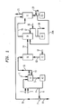
Figure 1 is a system flow diagram showing a prescrubber, a demisting section followed by separate vessels for oxidation and two step scrubbing sections interconnected by ducts. -
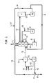
Figure 2 is a system flow diagram that shows integrated demisting, oxidation, and the two step scrubbing sections. -
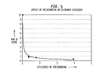
Figure 3 is a graph showing the effect of prescrubbing on secondary emissions. - The plants shown in
Figures 1 to 3 are suitable for treatment and removal of NOx, SOx, HCl, Hg, and other contaminants from an exhaust gas stream. In the example of a flue gas containing SO2, the flue gas is partially prescrubbed to remove the SO2 along with other contaminants to render the flue gas conducive to treatment with ozone. Such a prescrubber may use an aqueous stream with controlled SO2 absorption and is configured to minimize formation and carryover of fine droplets in the prescrubber exhaust. The droplets that are entrained in the prescrubber exhaust flue gas are physically separated or demisted by any one of a variety of means. The demisted prescrubber exhaust enters an oxidizer where it is brought in contact and mixed with oxidant such as ozone. - The ozone at a preselected molar ratio and at the preselected residence time of the oxidizer, transforms the NOx to higher orders of nitrogen oxides. Higher orders of nitrogen oxides are more reactive and readily soluble in most types of aqueous solutions. Oxidative conditions in the oxidizer also cause oxidation of other contaminants in the flue gas including but not limited to elemental Hg (mercury). The oxidized flue gas is then scrubbed selectively with aqueous stream in the main scrubber, which can be counter flow type, cross flow type or cocurrent type.
- Pre-scrubbing of the flue gas offers numerous advantages such as:
- 1) Generation of sulfite or sulfurous acid necessary for scavenging residual ozone from the scrubbed flue gas;
- 2) Reducing the ozone requirement for higher degree of NOx removal;
- 3) Facilitation of conditions favoring oxidation and removal of mercury and other contaminants;
- 4) Reducing emissions of NO2 in the treated flue gas.
- The process according to the present invention preferably comprises the following steps:
- The exhaust gas in the temperature range of 4,44-454,44°C (40-850°F) with contaminants is directed via duct to a prescrubber or a prescrubbing section. An evaporative cooler is generally added when the temperature preceding the prescrubber exceeds about 593,33°C (1100°F).
- In the prescrubber or prescrubbing section, exhaust gas is brought in contact with an aqueous solution in such a fashion so as to cause preferential scrubbing of some or substantial parts of SO2, most of the highly soluble gases and other contaminants. Absorption of SO2 results in the formation of sulfite, bisulfite, and or sulfurous acid into the aqueous phase. As absorption of O2 causes sulfite to oxidize to sulfate and O2 being far less soluble than SO2, the design of the prescrubber minimizes the absorption of O2. By appropriately manipulating pH, transfer area, and the contact time, selectivity of mass transfer with respect to SO2 is improved. The contact between the gas and the liquid phase in the prescrubber increases the water vapor content of the prescrubbed flue gas. In the case when flue gas is hotter than the contacting aqueous stream, this contact between gas and liquid results in simultaneous quenching along with absorption.
- Quenching raises the partial pressure of water vapor in the flue gas. All of these effects due to prescrubbing of the flue gas provide numerous advantages, including but not limited to generating sulfite solution needed for abating residual ozone; increasing water content of the flue gas entering the oxidizer to improve oxidative conditions; reducing SO2 and HCl content of the flue gas entering the oxidizer to improve oxidative conditions while making it possible to construct most of the oxidizer out of non-exotic materials; reducing SO2 content of prescrubbed gas stream; a highly oxidizing condition is created in the oxidizer improving oxidation of elemental mercury; providing the conditions to perform selective absorption of flue gas and other components in the scrubber; and avoiding absorption of NO in sulfite solution thereby forming the complex that has the potential to revert to NO.
- The prescrubbed gas is preferably demisted to remove droplets of aqueous solution entrained in the gas stream exiting the prescrubber. The demisting may take place simply by virtue of the geometrical arrangement of flow entering the demisting section. Droplets may be separated by either twisting and turning of flue gas induced by the liquid flow of the prescrubber or by demister or mist eliminator elements downstream of the prescrubber.
- Flue gas leaving the demisting section enters an oxidizer of preselected residence time to allow the ozone injected in the oxidizer to mix and react with NOx in the flue gas. The instantaneous and selective oxidation of NOx by ozone generates higher order oxides of nitrogen that are readily soluble in numerous aqueous solutions. A few other contaminants such as mercury (Hg) also oxidize in the oxidizer. Eliminating or reducing aqueous solution droplet carryover improves the efficiency with respect to ozone consumption and the consequent chemistry of absorption. It should be noted that to achieve low emissions of NOx, a stoichiometric excess of oxidant is used. This is made economically feasible by the method and apparatus of this invention which scrubs the excess ozone.
- The flue gas stream exiting the oxidizer is treated in the first scrubber where the oxidized form of NOx, remainder of SO2, oxidized form of mercury and other contaminants are scrubbed with an aqueous stream. The NOx and SOx in the oxidized flue gas on contacting the aqueous stream of the first step scrubber generate oxyacids. These oxyacids further continue the oxidative reactions, which are extremely conducive to the further oxidation of mercury and other contaminants. To maintain the required oxidative and absorption chemistry of gases, mercury, and other contaminants, a reagent of predetermined quantity is added. This reagent can be ammonia or alkali metal or alkaline earth metal oxides, carbonates, oxides or hydroxides. Consequently, complex salts are generated in the first step scrubber.
- As noted before, to achieve low emissions of NOx, a stoichiometric excess of oxidant is needed and therefore a second scrubber is needed for scrubbing the excess ozone. In addition if mercury is present, the two step scrubbing approach is essential for efficient mercury removal. The scrubbed flue gas which is substantially free from contaminants and oxidant is conveyed through a mist elimination section before safely exhausting to atmosphere.
- The flue gas flow can be as little as few hundreds of standard cubic feet per minute generated by industrial processes or as high as millions of cubic feet per minute generated by coal fired boilers engaged in large electric power generation. For example, as shown in
Figure 1 , theflue gas stream 1 ducted to the prescrubber could be from more than one coal fired boilers with flow totaling in excess of 10 million lbs/hr (4.45 million kg/hr). This prescrubber in actual practice can be a vessel mounted separately on a structure or a section of duct modified to provide functionality described in detail. - Based on the present state of knowledge about ozone generation and attainable power efficiencies, it is evident that ozone based technology may be economically less attractive when compared with combustion modification or reduction based technology using ammonia. Ozone generation requires about 10 to 14 kW per kilogram of ozone.
- Oxidation of NOx with ozone and subsequent high removal of NOx to low levels in a scrubber has been demonstrated. The treated gas stream from such a unit has been reported to have less than two (2) ppmv of NOx. Due to its ability to reach very low levels of NOx and simultaneously oxidize other contaminants both organic and inorganic, there exists an applicability of this process as an end of the pipe treatment system. This process can be applied in combination with other NOx control measures or technologies, which may be used upstream in the treatment of exhaust or flue gas stream.
- To meet the increasing need to lower the pollutant levels in the exhaust gases, ozone based oxidation processes will provide an effective solution. However, to achieve these low levels of pollutants, the ozone dosage will need to be in excess of the stoichiometry so that the oxidation and removal by scrubbing is possible in the new or retrofitted equipment. This excess ozone in the treated gas stream emitted to the atmosphere is not desirable. Skelley et al.,
US Patent No. 5, 316, 737 therefore, recommended use of sulfite solution formed in situ or adding the sulfite solution in the ultimate scrubbing step before exhausting to the atmosphere. - The prescrubber used in this invention is a device where gas and liquid is put in contact to cause the selective transfer of components from the gas to the liquid phase. Prescrubbing inadvertently can cause cooling which may or may not be beneficial to the oxidation of NOx (Skelley et al.) depending on degree of cooling, temperature of the untreated flue gas, moisture content of flue gas, etc. The principal intent of prescrubbing is to selectively scrub part or most of the SO2 to effectively generate sulfite solution, which not only reduces ozone consumption but also depletes the residual ozone concentration in the treated flue gas stream. Selective scrubbing also prevents absorption of NO in sulfite. Absorption of NO is not desirable as the solution resulting from scrubbing NO needs further processing during which NO could potentially desorb from the solution. The prescrubbing will also increase partial pressure of water vapor in the gas phase so that higher oxides of nitrogen formed in the reactor can be stabilized to form more stable oxyacids of NOx, which assist in further oxidation of Hg to enable stable removal in the scrubber.
- Furthermore, the partial removal of SO2 upstream of the main scrubber helps to alleviate the need for oxidation chemistry necessary to prevent re-emission of elemental mercury. Conventional scrubbers and quenchers used in the pollution control industry do not meet the expectations of a prescrubber required for the process claimed in this invention. The solubility of SO2 in an aqueous solution is many order of magnitudes greater than that of O2. Absorption of SO2 in aqueous medium containing alkali or alkaline carbonates or hydroxides, or oxides is enhanced due to chemical reaction, so too is the absorption of O2 in presence of sulfite. The actual mechanism of absorption of SO2 and O2 is somewhat complex. Characterization of ease in absorption as a "solubility" oversimplifies the phenomenon, however, it is major factor affecting preferential absorption of SO2 over O2.
- In order to cause selective transport of SO2 over other less soluble components, any of the following methods by itself or in combination may be used in no particular order of preference. For example, it may be by contacting gas with swirling liquid over conical surface; flowing gas through a curtain of larger droplets aqueous stream; contacting gas to wetted walls or surfaces of contactors; contacting gas stream with a spray producing larger liquid droplets; dynamically controlling the gas - liquid contact area; contacting gas and liquid followed by effective separation of liquid droplets from the gas phase; and limiting gas liquid contact time.
- In this type of selective prescrubber, sprays resulting in fine droplets are generally not preferred because of certain physical limitations, even though fine droplets offer far greater mass transfer area reducing selectivity to more soluble gases such as SO2, HCl, etc. Scrubbing of SO2 produces sulfurous acid in the liquid phase. In the presence of basic compounds, such as ammonia, carbonates, hydroxides, or alkaline earth metals, sulfurous acid transforms to sulfites. Finer droplets also form a mist, which entrains in the fast moving gas stream due to surface drag. These entrained droplets or mist of sulfites, bisulfites, and sulfurous acids are very effective in scavenging ozone and are undesirable in the oxidizer section.
- In addition, the fine droplets offer much larger surface area per unit volume of aqueous stream requiring extending treatment time to reduce the entrainment to the oxidizer section. This enables oxygen in the flue gas to be absorbed and thereby convert much needed sulfite of this invention to sulfate salt that plays no role in residual ozone destruction.
- To minimize the generation of fine mist and the absorption of oxygen, it is necessary not only to first reduce the gas-liquid contact area but also to reduce the contact time between the flue gas and the aqueous stream, its mist or droplets.
- It should be noted that the flue gas exiting such a prescrubber might be partially saturated or fully saturated with water vapor. In order to reduce the liquid droplets from the gas phase exiting the prescrubber, the gas stream needs to be demisted. This demisting may consist of device such as Chevron or wire mesh pad placed in a flue gas path to twist and turn the flue gas stream. Other ways of demisting are to allow the higher momentum of liquid droplets to impact on extended surfaces for the droplets to coalesce and drain down under gravity. When the flue gas has high loading of particulate matters, use of an in-line device may be limited. In such a case, liquid droplets can also be removed by simply setting up motion of flue gas in such a way that majority of droplets fall out due to change in the velocity of the flue gas. Changing either direction or speed of gas flow can cause droplet separation, or in some cases, the combination of both may be gainfully used.
- Velocity can be changed by changing geometry of the downstream vessel such as tangential introduction into cylindrical vessel where droplets under centrifugal force contact the cylindrical vessel surface, coalesce and drain down under gravity while the gas travels up in spiral path. Prescrubber sprays introduced to scrub the gas can also cause swirl necessary in the exiting stream. Gases exiting the prescrubber open into large cross section vessel to cause reduction of velocity to allow fallout of larger droplets.
- Turning now to the figures, as depicted in
Figure 1 ,flue gas 1 is selectively scrubbed in a prescrubber A by contacting withliquid stream 4. The prescrubber A has its own liquid recirculation loop by pumpingliquid stream 5 back toform 4. Thisstream 4 is supplemented with alkali feed throughline 2 and make up water throughline 3 to maintain a desired pH and the solid contents. Some of the liquid from recirculation loop is withdrawn via 9 to feed the scrubber E. Depending on ability of the scrubber to handle solids, asolids rejection device 7 fed throughline 6 is placed upstream of feeding the scrubber E. This solids rejection device may be a filter, a hydroclone, a settling tank, etc. The liquid stream fromfilter 7 can be fed to a filtered solids bed throughline 8. -
Line 5 also feeds pump A1 which can deliver liquid throughline 4 back toprescrubber A. Line 10 leaves the prescrubber A with asmall recycle line 11 back to theprescrubber A. Line 10 brings the liquid to oxidizerB. Line 14 connects oxidizer B and first step scrubber D. Pump D1 feeds throughline 17 to the first step scrubber D. -
Line 15 exits first step scrubber D to second step scrubber E which is fed from pump E1 throughline 20.Line 21 exits the second step scrubber E and allows gases to be fed to the atmosphere. - It may be noted that in some applications, a separate prescrubbing recirculation loop need not be used. Instead of the recirculation loop, a part of liquid stream through
line 4 may be fed to prescrubber A and the resulting liquid throughline 5 is then brought back to the sump of scrubber E. - The ozone generator C receives
gas feed stream 12, which is dried air, oxygen, or mixture of air and oxygen. In large applications, use of oxygen is generally found to be more cost effective. Oxygen is generally supplied in a liquid form or produced on site using a cryogenic or non-cryogenic air separation unit. Industrial gas companies worldwide have catered to and tailored the need for oxygen in refining, chemical processing, glass, steel and many other process industries. - Commercially available ozone generators include a single-pass, shell-and-tube heat exchanger, with cooling water on the shell-side and oxygen flowing through the tubes made of stainless steel. Each tube acts as a grounded electrode that houses a high voltage electrode in the center separated by a dielectric and concentric volume through which compressed air or oxygen flows. This high voltage current causes corona discharge, which energizes oxygen molecules and results in the formation of ozone.
- The
gas stream 12 fed to ozone generator(s) C forms ozone at concentrations ranging from 2 to 18 percent or higher depending on the power fed to electrodes. The ozone containinggas stream 13 is mixed with prescrubbed and demisted gas in the oxidizer vessel B. The injection of ozone is generally upstream of the oxidation vessel. The distribution of the ozone in the flue gas stream is of key importance to ensure complete mixing. If the distribution of ozone is incomplete, NOx removal efficiency reduces followed by number of problems in the scrubbing that can result in not meeting the objectives of this invention. With advances in computers and computational techniques and tools based on computational fluid dynamics (CFD), ozone distribution design can be established with greater confidence. - Ozone is introduced in the flue gas stream by an ozone injection grid that ensures adequate distribution of O3 to mix with the flue gas in a relatively short time period. As mentioned earlier, ozone is mixed upstream of oxidizer vessel itself. Essentially, oxidation begins after ozone mixes with the flue gas. The oxidation section or oxidation chamber is also denoted as oxidizer B in
Figures 1 to 3 . In this chamber B, NOx, SOx, CO and other contaminants are oxidized by the presence of the ozone. Sets of overall reactions that transform NO to NO2, NO3, and N2O5 in chamber B and oxidize other contaminants are as follows: *
NO + O3 ---------->NO2 + O2 (1)
NO2 + O3 ---------->NO3 + O2 (2)
NO3 + NO2 <=====> N2O5 (3)
2NO2 <=====> N2O4 (4)
NO + NO2 <=====> N2O3 (5)
2O3 ----------> 3O2 (6)
SO2 + O3 ----------> SO3 (7)
CO+O3 ----------> CO2 (8)
- Other contaminants such as elemental mercury also oxidize in the oxidizer.
Hg0 -O3 ----------> Hg-2 + O2 (9)
- Since the flue gas is prescrubbed, moisture level or humidity is likely to be higher. In addition to oxidation reactions forming oxy acids of NOx, oxy acids of NOx and SOx will also form in the gas phase,
N2O5 + H2O(g) ----------> 2 HNO3(g) (10)
SO2 + H2O(g) <=====> H2SO3(g) (11)
N2O3 + H2O(g) <=====> 2 HNO2(g) (12)
- Some enhancement is also observed in the oxidation of elemental mercury in presence of nitric acid in the gas phase. However, the presence of SO2 inhibits mercury oxidation. Therefore, it is advantageous to remove part of or a substantial amount of SO2 in the prescrubber. Ozone in the presence of higher moisture content also forms some hydroxyl (OH-) radical which is known to oxidize mercury and other contaminants. The apparent high oxidation rates of mercury oxidation is the cumulative effect of ozone, water vapor and oxy acids of nitrogen.
Reactions 1 through 12 represents simplified chemistry of oxidation in homogenous phase in the oxidizer. - Water found in the form of liquid droplets in the oxidizer forms the hetrogeneous phase. NOx, SOx and other contaminants will begin absorbing in the droplets. NOx forms nitrous and nitric acid while absorption of SOx results in sulfurous acid.
N2O5 + H2O(I) ----------> HNO3(I) (13)
SO2 + H2O(I) ----------> H2SO3(I) (14)
HNO3(g) ----------> HNO3(I) (15)
H2SO3(g) ----------> H2SO3(I) (16)
HNO2(g) ------> HNO2(I) (17)
- Many other reactions such as following also contribute some minor amount of NOx removal.
N2O4 + H2O(I) ----------> HNO3(I) + HNO2(I) (18)
2 NO2 + H2O(I) ----------> HNO3(I) + HNO2(I) (19)
N2O3 + H2O(g) ----------> 2 HNO2(I) (20)
- Some of the nitrous acid decomposes due to instability in the aqueous phase.
3 HNO2(I) ----------> HNO3(I) + 2 NO(g) + 2 N2O (21)
- In presence of compounds of alkali metals and alkaline earth metals that are basic or other basic compounds, respective nitrate and sulfites are formed in the droplets. For example,
2 HNO3(I) + Na2CO3(I) ----------> 2 NaNO3(I) +H2O(I) + CO2 (22)
H2SO3(I) + Na2CO3(I) ----------> 2 Na2SO3(I) + H2O(I) + CO2 (23)
2 HNO2(I) + Na2CO3(I) ----------> 2 NaNO2(I) +H2O(I) + CO2 (24)
- Solubility of oxygen and ozone is very limited in the aqueous phase. Due to the chemical reaction in the liquid phase, mass transport of oxygen and ozone from gas phase to liquid phase increases. In particular, absorption of ozone in these droplets is dramatically enhanced by sulfites or sulfurous acid already present and formed in the the oxidizer. This substantially increases consumption of ozone which is highly undesirable.
O3(I) + Na2SO3(I) ----------> 2 Na2SO4(I) + O2 (25)
O3(I) + NaNO2(I) ----------> NaNO3(I) + O2 (26)
- The principal reactions of ozone in oxidation of NOx are NO oxidation to NO2 as depicted by reaction (1) and NO2 oxidation further to NO3 as depicted by reaction (2). Since the former reaction is faster than latter, ozone deficiency will leave NO2 partly unoxidized. This can be somewhat compensated by the addition of a stoichiometric excess of ozone. SOx removed as sulfite in the oxidizer by absorption on liquid droplet is now not available in the scrubber E for scavanging unreacted oxidant. For this reason, it is advantageous to have oxidizer flue gas substantially free of liquid droplets.
- The oxidized gas stream exiting the oxidizer is then introduced in the scrubber D where it is contacted with aqueous liquid stream. In a dual step scrubbing process, chemistry of scrubbing medium in the first step D is oxidative while the second step is rich in sulfite. The scrubbers can be packed column, spray column, plate column, tray column, cross flow, counter current or cocurrent. It is believed that each step of absorption can consist of more than one "Theoretical Stage of Mass Transfer". Highly oxidized forms of NOx such as N2O5, NO3 and other extremely soluble gases that escape the prescrubber A, such as HCl and HF, are presenti n the gas entering the first scrubber. It is this gas which is the most acidic and the most reactive with ozone. With a prescrubber, some or a part of SOx has already been removed. In addition, SO2 is far less soluble than oxidized form of NOx.
- Hence, due to the prescrubber and improved process of oxidation, an initial highly oxidative and acidic zone may be created which is critical in improving capture and stabilization of mercury. In the scrubbing step, some oxidation within the gas phase continues while dissolution of contaminants occur in the liquid. Once the desired amount of NOx is absorbed, less soluble SO2 absorption proceeds. The chemistry of dissolution of all these gases is described in the reactions (13) through (24). The absorption of remainder of SO2 produces sulfites. It is well reported in both technical papers (Jethani et al.) and the patent literature that in NOx lower oxides of nitrogen can be removed by scrubbing with sulfite solution. In particular, sulfite is effective in the removal of NO2. The less oxidized form of NOx at this step mainly comprises NO and NO2. NO is colorless while NO2 is dark brown in color and in the treated gas stream contributes to opacity. Therefore, deferring SO2 absorption to the latter zone brings three additional advantages as follows it helps to scavenge residual ozone; it further reduces level of NOx in the gas stream leaving this scrubber step and it reduces opacity of treated gas stream.
- As depicted in
Figure 1 , the scrubbing section comprises two steps. The sulfite rich stream from prescrubber A is fed to the second scrubber E of the scrubbing system. In an individual case,line 9 may be fed to the sump of second scrubber E. The liquid stream bleed 20A from second step is conveyed to the first step of the scrubbing section. As mentioned above to maintain the reducing chemistry and to enhance capture of SO2, pH is continuosly monitored and adjusted byalkali feed 19. In the first scrubber D, highly oxidized NOx, some ozone and highly soluble gases are scrubbed out. Thealkali feed line 16 provides adjustment of pH to maintain desired chemistry in this scrubbing step. Bleed from this stage is conveyed byline 18 to a waste water treatment plant. Unlike conventional scrubbers since bleed is from the most oxidative step, COD (chemical oxygen demand) of the waste stream is low, minimizing the power intensive need of oxidative treatment. - In the embodiment of
Figure 2 , the oxidiser, first scrubber and second scrubber are all provided in different regions of the same liquid-vapour contact vessel which may contain trays or packing to effect intimate contact between an ascending gas phase and a descending liquid phase. - In
Figure 2 , flue gas is fed to the pre-scrubber J throughline 51. Alkali and make up water are fed throughlines line 53 which feeds the pre-scrubber J. Scrubbed liquid passes throughline 52 to pump J1 and can be recirculated back to the scrubber J throughline 53 or delivered to a second scrubber K3 throughline 59.Line 56 exits pump J1 throughline 56 to afilter assembly 57 which has a filtered solids bleedline 58 and also thefeed line 59 exiting from it.Line 55 delivers the make up water to oxidizer K1 which receives an ozone and oxygen mixture throughline 71 from ozone generator L which receives oxygen feed throughline 60.Line 62 connects oxidizer K1 with a first step scrubber K2. Scrubber K2 is adjacent second step scrubber K3 which will release the scrubbed gases to the atmosphere throughline 71. Pump K4 feeds the first step scrubber K2 throughline 63 which is fed alkali throughline 68 and through which bleeds to a waste water treatment plant exits throughline 69. Some scrubbed solution exits second stage scrubber K3 throughline 64 which connects to a recycletank M. Line 65 exits the recycle tank to pump M1 which will pump liquid throughline 66 back to the second step scrubber K3. Alkali feed may also be inputted into this liquid throughline 67. Alternatively this liquid feed fromline 66 may be diverted throughline 70 back to the oxidizer K1 for further treatment. - In another embodiment, instead of a sodium based reagent, lime or limestone based reagents are used in prescrubbing as well as scrubbing section. When a limestone based reagent is used, recirculating solution from scrubber D is oxidized with air. Alkali scrubbing, i.e. sodium or potassium based reagent is more prevelant in industrial and petrochemical applications. In a further embodiment, combination of alkali and alkaline earth metal salts are used where alkali is recycled and alkaline earth metal salts of oxy acids of sulfur and nitrogen are separated with alkaline earth metal carbonates/hydroxides replenished.
- In one example of operation of a plant such as that shown in
Figure 1 , a flue gas stream with 2,420 scfm of flow with 24.2 ppm of NOx (almost all NO) was treated with ozone in an oxidizer. The gas exiting the oxidizer was scrubbed with a sodium carbonate solution. In the scrubbing section D there was no sulfite present, there was 9.8 ppm of residual ozone with 7.5 ppm of NO2 in the flue gas stream entering scrubbing section E. Sodium sulfite present in recirculating liquid of section E eliminated almost all residual ozone to less than 0.38 ppm and decreased NO2 emissions to less than 2 ppm to atmosphere. As shown in Figure 4, with an increase in prescrubber efficiency, there is an increase in NOx removal efficiency and significant decrease in residual ozone emitted to the atmosphere.
Claims (6)
- A process for removing contaminants comprising oxides of sulfur and oxides of nitrogen from a flue gas stream comprising the steps:a) feeding said gas flue stream into a prescrubber, in which there is an aqueous medium containing alkali or alkaline carbonates, hydroxides or oxides, and in which sulphite or sulphurous acid necessary to scavenging of ozone in step (e) below is generated;b) demisting the flue gas stream exiting the prescrubber;c) feeding the demisted gas stream from said prescrubber and an ozone stream into an oxidation zone;d) feeding said gas stream from said oxidation zone to a first scrubber in which an oxidative condition is maintained; ande) feeding said gas stream from said first scrubber into a second scrubber, in which sulphite of sulphurous acid from the prescrubber is employed to scavenge ozone from the gas stream.
- A process as claimed in claim 1, wherein said contaminants further comprise acid gases and heavy metals.
- A process as claimed in claim 2, wherein said oxidation zone oxidizes nitrogen oxides and heavy metals.
- A process as claimed in any one of the preceding claims, wherein said oxidiser zone, said first scrubber and said second scrubber are contained in a single vessel.
- A process as claimed in claim 4, wherein said vessel is a liquid-vapour contact vessel and the said oxidation zone, the first scrubber and the second scrubber are arranged vertically therein.
- A process as claimed in claim 5, wherein said oxidation zone is the bottom level and said second scrubber is the top level.
Applications Claiming Priority (4)
| Application Number | Priority Date | Filing Date | Title |
|---|---|---|---|
| US948928 | 1997-10-10 | ||
| US51246903P | 2003-10-17 | 2003-10-17 | |
| US512469P | 2003-10-17 | ||
| US10/948,928 US7303735B2 (en) | 2003-10-17 | 2004-09-24 | Process for the removal of contaminants from gas streams |
Publications (2)
| Publication Number | Publication Date |
|---|---|
| EP1524023A1 EP1524023A1 (en) | 2005-04-20 |
| EP1524023B1 true EP1524023B1 (en) | 2009-05-06 |
Family
ID=34381392
Family Applications (1)
| Application Number | Title | Priority Date | Filing Date |
|---|---|---|---|
| EP04256401A Active EP1524023B1 (en) | 2003-10-17 | 2004-10-18 | Process for the removal of NOx, SOx and contaminants from gas streams |
Country Status (6)
| Country | Link |
|---|---|
| US (1) | US7303735B2 (en) |
| EP (1) | EP1524023B1 (en) |
| CN (1) | CN100418611C (en) |
| AT (1) | ATE430617T1 (en) |
| AU (1) | AU2004220725B8 (en) |
| DE (1) | DE602004020956D1 (en) |
Families Citing this family (47)
| Publication number | Priority date | Publication date | Assignee | Title |
|---|---|---|---|---|
| US7628967B2 (en) | 2002-10-01 | 2009-12-08 | Airborne Industrial Minerals, Inc. | Removal of Hg, NOx, and SOx with using oxidants and staged gas/liquid contact |
| US7766995B2 (en) * | 2006-05-01 | 2010-08-03 | Linde Llc | Ozone production processes and its use in industrial processes |
| CA2618778C (en) * | 2007-01-23 | 2016-04-05 | Linde, Inc. | Process for removing contaminants from gas streams |
| CN100496672C (en) * | 2007-04-30 | 2009-06-10 | 武汉凯迪电力环保有限公司 | Wet flue gas desulfurizing and hydrargyrum-removing technology based on two-stage oxidation reaction and system thereof |
| US7842114B2 (en) * | 2008-07-18 | 2010-11-30 | Uop Llc | Vessel for receiving a fluid including a demister |
| CN101347710B (en) * | 2008-09-04 | 2012-10-03 | 北京博奇电力科技有限公司 | Purification system of flue gas and method |
| CN101485957B (en) * | 2009-01-08 | 2011-05-11 | 浙江大学 | Device and method of simultaneous desulfuration and denitration for flue gas using ozone oxygenation combined with double-tower washing |
| KR101094672B1 (en) * | 2009-03-17 | 2011-12-20 | 한국과학기술연구원 | Method and apparatus for the treatment of nitrogen oxides using an ozone and catalyst hybrid system |
| WO2010132785A2 (en) | 2009-05-15 | 2010-11-18 | Cummins Filtration Ip, Inc. | Surface coalescer |
| CN102210966A (en) * | 2010-04-02 | 2011-10-12 | 航空工业矿石公司 | Method for purifying flue gas |
| CN101879404B (en) * | 2010-07-12 | 2013-01-30 | 华东理工大学 | Recycled flue gas desulfurization and denitration method |
| US8574521B2 (en) * | 2010-09-29 | 2013-11-05 | Linde Aktiengesellschaft | Gas stream purification apparatus and method |
| US9272908B2 (en) | 2010-09-29 | 2016-03-01 | Linde Aktiengesellschaft | Gas stream purification apparatus |
| KR101266258B1 (en) * | 2011-01-28 | 2013-05-22 | 한국에너지기술연구원 | A fuel gas treatment apparatus for Carbon dioxide capture process and the method |
| KR20140017573A (en) * | 2011-02-01 | 2014-02-11 | 린데 악티엔게젤샤프트 | Process for removing contaminants from gas streams |
| US20130183219A1 (en) | 2011-07-25 | 2013-07-18 | Gene H. Irrgang | Methods for reducing nitrogen oxides emissions |
| CN102335539A (en) * | 2011-09-06 | 2012-02-01 | 江苏华正环保科技有限公司 | Process for removing tobacco odour |
| CN102389698A (en) * | 2011-09-16 | 2012-03-28 | 百力达太阳能股份有限公司 | Effective method for industrial fluorinion-containing waste gas treatment |
| EP2659947A1 (en) | 2012-04-30 | 2013-11-06 | Linde Aktiengesellschaft | Method and apparatus for removing contaminants from exhaust gases |
| US8734741B1 (en) | 2012-04-30 | 2014-05-27 | Linde Aktiengesellschaft | Methods for removing contaminants from exhaust gases |
| EP2719440B1 (en) | 2012-10-15 | 2017-04-19 | Linde Aktiengesellschaft | Method for removing contaminants from exhaust gases by adding ozone |
| US10058808B2 (en) | 2012-10-22 | 2018-08-28 | Cummins Filtration Ip, Inc. | Composite filter media utilizing bicomponent fibers |
| US8871166B2 (en) * | 2013-01-16 | 2014-10-28 | Linde Aktiengesellschaft | Method for removing contaminants from exhaust gases |
| CA2924760A1 (en) * | 2013-09-25 | 2015-05-21 | Linde Aktiengesellschaft | Methods for treating waste gas streams from incineration processes |
| CN105579116A (en) * | 2013-09-25 | 2016-05-11 | 琳德股份公司 | Methods for treating waste gas streams from incineration processes |
| CN103566725B (en) * | 2013-10-15 | 2016-03-02 | 中国科学院过程工程研究所 | A kind of circulating fluid bed semi-drying method combined desulfurization and denitration mercury removal device and method |
| WO2015092547A2 (en) | 2013-12-16 | 2015-06-25 | Linde Aktiengesellschaft | Methods for removing contaminants from exhaust gases |
| EP2883593A1 (en) * | 2013-12-16 | 2015-06-17 | Linde Aktiengesellschaft | Method for removing contaminants from exhaust gases |
| CN104107627A (en) * | 2014-07-21 | 2014-10-22 | 中国科学院过程工程研究所 | Device and method for cooperative desulfurization, denitration, demercuration and dioxin removal of sintering flue gas by virtue of circulating fluidized bed semidry method |
| US9895659B2 (en) | 2014-09-24 | 2018-02-20 | Linde Aktiengesellschaft | Methods for removing contaminants from exhaust gases |
| EP3012011A1 (en) | 2014-10-21 | 2016-04-27 | Linde Aktiengesellschaft | Method and apparatus for partial removal of contaminants from process gas stream |
| WO2016180676A1 (en) * | 2015-05-08 | 2016-11-17 | Yara International Asa | Reduction of nox emissions by effluent gases from fertilizer production with ozone injection and wet scrubbing |
| CN104941412A (en) * | 2015-06-05 | 2015-09-30 | 北京中晶佳镁环境科技股份有限公司 | Flue gas desulphurization-denitration integrated device and method |
| CN105435611A (en) * | 2015-12-16 | 2016-03-30 | 榆林学院 | Two-stage porous absorption device for removing SO2 in flue gas by using coke quenching waste water |
| US9764281B2 (en) | 2015-12-18 | 2017-09-19 | Cannon Technology, Inc. | Process for the removal of contaminants from flue gas streams |
| US10065151B2 (en) | 2015-12-21 | 2018-09-04 | Linde Aktiengesellschaft | Methods for removing contaminants from gas streams |
| WO2018017701A1 (en) | 2016-07-19 | 2018-01-25 | Cummins Filtration Ip, Inc. | Perforated layer coalescer |
| WO2018092041A1 (en) * | 2016-11-15 | 2018-05-24 | 8 Rivers Capital, Llc | Removal of impurities from a process stream by contacting it with an oxidant and with an aqueous stream |
| US10744456B2 (en) | 2017-01-13 | 2020-08-18 | EnviroEnergy Solutions, Inc. | Wet electrostatic gas cleaning system with non-thermal plasma for NOx reduction in exhaust |
| FI128556B (en) * | 2017-04-04 | 2020-08-14 | Valmet Technologies Oy | Method for treating a gas flow and emission control arrangement |
| CN107213769B (en) * | 2017-05-25 | 2019-09-20 | 江苏新世纪江南环保股份有限公司 | A kind of ammonia method desulfurizing method and device of locellus ammonification |
| NL2018994B1 (en) * | 2017-05-30 | 2018-12-07 | Koninklijke De Vries Scheepsbouw B V | Process and apparatus for reducing NOx emissions |
| EP3549661A1 (en) | 2018-04-06 | 2019-10-09 | Yara International ASA | Nox removal from gaseous effluents |
| CN110479070A (en) * | 2018-05-15 | 2019-11-22 | 三星工程株式会社 | The sweep-out method and device of nitrogen oxides of exhaust gas |
| SE543244C2 (en) | 2019-03-06 | 2020-10-27 | 3Nine Ab | Method and installation for reduction of sulphur dioxides in exhaust gases from a marine diesel engine |
| CN110813056A (en) * | 2019-11-27 | 2020-02-21 | 福建省清流县东莹化工有限公司 | Novel tail gas treatment process |
| EP3875167A1 (en) | 2020-03-06 | 2021-09-08 | Linde GmbH | Improved nox removal method |
Family Cites Families (22)
| Publication number | Priority date | Publication date | Assignee | Title |
|---|---|---|---|---|
| JPS5215265B2 (en) * | 1973-03-03 | 1977-04-27 | ||
| JPS49126566A (en) * | 1973-04-10 | 1974-12-04 | ||
| JPS5643771B2 (en) * | 1973-12-18 | 1981-10-15 | ||
| GB1505169A (en) * | 1974-11-02 | 1978-03-30 | Fuji Kasui Eng Co Ltd | Process for removing nitrogen oxides from waste gas |
| JPS51143569A (en) * | 1975-06-06 | 1976-12-09 | Mitsubishi Heavy Ind Ltd | A wet exhaust gas treatment process |
| JPS5311164A (en) * | 1976-07-17 | 1978-02-01 | Ishikawajima Harima Heavy Ind Co Ltd | Wet desulfurizing and denitrating apparatus for flue gas |
| JPS5314662A (en) * | 1976-07-28 | 1978-02-09 | Hitachi Ltd | Method for decreasing nitrogen oxides concentration of combustion exhaust gas |
| US4247321A (en) * | 1979-05-21 | 1981-01-27 | Persinger James G | Method and apparatus for obtaining fertilizing solution from fossil fueled stationary engines |
| DE3220403C1 (en) * | 1982-05-29 | 1983-11-17 | Buckau-Walther AG, 4048 Grevenbroich | Process for removing acidic components and nitrogen oxides from exhaust gases |
| DE3233316A1 (en) * | 1982-09-08 | 1984-03-08 | Buckau-Walther AG, 4048 Grevenbroich | METHOD FOR REMOVING STICKOXYDES FROM EXHAUST GASES |
| DE3739162A1 (en) * | 1987-11-19 | 1989-06-01 | Krupp Koppers Gmbh | METHOD FOR THE REMOVAL OF ACIDIC COMPONENTS AND NITROGEN OXIDES FROM THE EXHAUST GASES OF INDUSTRIAL FIRING SYSTEMS |
| US5206002A (en) * | 1991-08-29 | 1993-04-27 | Cannon Boiler Works, Inc. | Process for removing nox and sox from exhaust gas |
| FI96387C (en) * | 1994-09-19 | 2001-12-03 | Kvaerner Pulping Oy | A method for removing nitrogen oxides from the flue gases of a pulp mill |
| CA2263233C (en) * | 1996-10-09 | 2002-01-15 | Zero Emissions Technology Inc. | Barrier discharge conversion of so2 and nox to acids |
| US5985223A (en) * | 1998-06-02 | 1999-11-16 | The Boc Group, Inc. | Removal of NOx and SOx emissions form pickling lines for metal treatment |
| US6162409A (en) * | 1999-03-15 | 2000-12-19 | Arthur P. Skelley | Process for removing Nox and Sox from exhaust gas |
| US6197268B1 (en) * | 1999-07-02 | 2001-03-06 | The Boc Group, Inc. | Reduction of toxic substances in waste gas emissions |
| US6231824B1 (en) * | 1999-08-10 | 2001-05-15 | The Boc Group, Inc. | Removal of nitric oxide from gas streams |
| US6136284A (en) * | 1999-12-09 | 2000-10-24 | The Boc Group, Inc. | Process for the removal of nitrogen oxides from gas streams |
| US6936231B2 (en) * | 2001-12-06 | 2005-08-30 | Powerspan Corp. | NOx, Hg, and SO2 removal using ammonia |
| US6761863B2 (en) * | 2002-01-29 | 2004-07-13 | The Boc Group, Inc. | Process for the removal of impurities from gas streams |
| US6649132B1 (en) * | 2002-07-23 | 2003-11-18 | The Boc Group, Inc. | Process for the removal of impurities from gas streams |
-
2004
- 2004-09-24 US US10/948,928 patent/US7303735B2/en active Active
- 2004-10-14 AU AU2004220725A patent/AU2004220725B8/en not_active Ceased
- 2004-10-17 CN CNB2004100981403A patent/CN100418611C/en not_active Expired - Fee Related
- 2004-10-18 DE DE602004020956T patent/DE602004020956D1/en active Active
- 2004-10-18 EP EP04256401A patent/EP1524023B1/en active Active
- 2004-10-18 AT AT04256401T patent/ATE430617T1/en not_active IP Right Cessation
Also Published As
| Publication number | Publication date |
|---|---|
| CN1660476A (en) | 2005-08-31 |
| AU2004220725B2 (en) | 2010-04-22 |
| CN100418611C (en) | 2008-09-17 |
| US20050084436A1 (en) | 2005-04-21 |
| AU2004220725A1 (en) | 2005-05-05 |
| EP1524023A1 (en) | 2005-04-20 |
| US7303735B2 (en) | 2007-12-04 |
| ATE430617T1 (en) | 2009-05-15 |
| DE602004020956D1 (en) | 2009-06-18 |
| AU2004220725B8 (en) | 2010-08-19 |
Similar Documents
| Publication | Publication Date | Title |
|---|---|---|
| EP1524023B1 (en) | Process for the removal of NOx, SOx and contaminants from gas streams | |
| US7052662B2 (en) | NOx, Hg, and SO2 removal using alkali hydroxide | |
| CA2927588C (en) | Method and apparatus for removing contaminants from exhaust gases | |
| AU2018328418B2 (en) | Method for controlling aerosol production during absorption in ammonia desulfurization | |
| US6991771B2 (en) | NOx, Hg, and SO2 removal using ammonia | |
| US4102982A (en) | Process for treating stack gases | |
| US4369167A (en) | Process for treating stack gases | |
| US5670122A (en) | Methods for removing air pollutants from combustion flue gas | |
| TWI432253B (en) | Ozone production processes and its use in industrial processes | |
| EP2499091A1 (en) | Process for removing contaminants from gas streams | |
| EP3012011A1 (en) | Method and apparatus for partial removal of contaminants from process gas stream | |
| CA2484727C (en) | Improved process for the removal of contaminants from gas streams |
Legal Events
| Date | Code | Title | Description |
|---|---|---|---|
| PUAI | Public reference made under article 153(3) epc to a published international application that has entered the european phase |
Free format text: ORIGINAL CODE: 0009012 |
|
| AK | Designated contracting states |
Kind code of ref document: A1 Designated state(s): AT BE BG CH CY CZ DE DK EE ES FI FR GB GR HU IE IT LI LU MC NL PL PT RO SE SI SK TR |
|
| AX | Request for extension of the european patent |
Extension state: AL HR LT LV MK |
|
| 17P | Request for examination filed |
Effective date: 20050422 |
|
| AKX | Designation fees paid |
Designated state(s): AT BE BG CH CY CZ DE DK EE ES FI FR GB GR HU IE IT LI LU MC NL PL PT RO SE SI SK TR |
|
| RTI1 | Title (correction) |
Free format text: PROCESS FOR THE REMOVAL OF NOX, SOX AND CONTAMINANTS FROM GAS STREAMS |
|
| GRAP | Despatch of communication of intention to grant a patent |
Free format text: ORIGINAL CODE: EPIDOSNIGR1 |
|
| GRAS | Grant fee paid |
Free format text: ORIGINAL CODE: EPIDOSNIGR3 |
|
| GRAA | (expected) grant |
Free format text: ORIGINAL CODE: 0009210 |
|
| AK | Designated contracting states |
Kind code of ref document: B1 Designated state(s): AT BE BG CH CY CZ DE DK EE ES FI FR GB GR HU IE IT LI LU MC NL PL PT RO SE SI SK TR |
|
| REG | Reference to a national code |
Ref country code: GB Ref legal event code: FG4D |
|
| REG | Reference to a national code |
Ref country code: CH Ref legal event code: EP |
|
| REG | Reference to a national code |
Ref country code: IE Ref legal event code: FG4D |
|
| REF | Corresponds to: |
Ref document number: 602004020956 Country of ref document: DE Date of ref document: 20090618 Kind code of ref document: P |
|
| REG | Reference to a national code |
Ref country code: SE Ref legal event code: TRGR |
|
| PG25 | Lapsed in a contracting state [announced via postgrant information from national office to epo] |
Ref country code: PT Free format text: LAPSE BECAUSE OF FAILURE TO SUBMIT A TRANSLATION OF THE DESCRIPTION OR TO PAY THE FEE WITHIN THE PRESCRIBED TIME-LIMIT Effective date: 20090906 Ref country code: AT Free format text: LAPSE BECAUSE OF FAILURE TO SUBMIT A TRANSLATION OF THE DESCRIPTION OR TO PAY THE FEE WITHIN THE PRESCRIBED TIME-LIMIT Effective date: 20090506 Ref country code: ES Free format text: LAPSE BECAUSE OF FAILURE TO SUBMIT A TRANSLATION OF THE DESCRIPTION OR TO PAY THE FEE WITHIN THE PRESCRIBED TIME-LIMIT Effective date: 20090817 |
|
| PG25 | Lapsed in a contracting state [announced via postgrant information from national office to epo] |
Ref country code: SI Free format text: LAPSE BECAUSE OF FAILURE TO SUBMIT A TRANSLATION OF THE DESCRIPTION OR TO PAY THE FEE WITHIN THE PRESCRIBED TIME-LIMIT Effective date: 20090506 Ref country code: PL Free format text: LAPSE BECAUSE OF FAILURE TO SUBMIT A TRANSLATION OF THE DESCRIPTION OR TO PAY THE FEE WITHIN THE PRESCRIBED TIME-LIMIT Effective date: 20090506 |
|
| PG25 | Lapsed in a contracting state [announced via postgrant information from national office to epo] |
Ref country code: CZ Free format text: LAPSE BECAUSE OF FAILURE TO SUBMIT A TRANSLATION OF THE DESCRIPTION OR TO PAY THE FEE WITHIN THE PRESCRIBED TIME-LIMIT Effective date: 20090506 Ref country code: DK Free format text: LAPSE BECAUSE OF FAILURE TO SUBMIT A TRANSLATION OF THE DESCRIPTION OR TO PAY THE FEE WITHIN THE PRESCRIBED TIME-LIMIT Effective date: 20090506 Ref country code: EE Free format text: LAPSE BECAUSE OF FAILURE TO SUBMIT A TRANSLATION OF THE DESCRIPTION OR TO PAY THE FEE WITHIN THE PRESCRIBED TIME-LIMIT Effective date: 20090506 Ref country code: RO Free format text: LAPSE BECAUSE OF FAILURE TO SUBMIT A TRANSLATION OF THE DESCRIPTION OR TO PAY THE FEE WITHIN THE PRESCRIBED TIME-LIMIT Effective date: 20090506 |
|
| PG25 | Lapsed in a contracting state [announced via postgrant information from national office to epo] |
Ref country code: BE Free format text: LAPSE BECAUSE OF FAILURE TO SUBMIT A TRANSLATION OF THE DESCRIPTION OR TO PAY THE FEE WITHIN THE PRESCRIBED TIME-LIMIT Effective date: 20090506 Ref country code: SK Free format text: LAPSE BECAUSE OF FAILURE TO SUBMIT A TRANSLATION OF THE DESCRIPTION OR TO PAY THE FEE WITHIN THE PRESCRIBED TIME-LIMIT Effective date: 20090506 |
|
| PLBE | No opposition filed within time limit |
Free format text: ORIGINAL CODE: 0009261 |
|
| STAA | Information on the status of an ep patent application or granted ep patent |
Free format text: STATUS: NO OPPOSITION FILED WITHIN TIME LIMIT |
|
| PG25 | Lapsed in a contracting state [announced via postgrant information from national office to epo] |
Ref country code: BG Free format text: LAPSE BECAUSE OF FAILURE TO SUBMIT A TRANSLATION OF THE DESCRIPTION OR TO PAY THE FEE WITHIN THE PRESCRIBED TIME-LIMIT Effective date: 20090806 |
|
| 26N | No opposition filed |
Effective date: 20100209 |
|
| PG25 | Lapsed in a contracting state [announced via postgrant information from national office to epo] |
Ref country code: MC Free format text: LAPSE BECAUSE OF NON-PAYMENT OF DUE FEES Effective date: 20091031 |
|
| REG | Reference to a national code |
Ref country code: CH Ref legal event code: PL |
|
| REG | Reference to a national code |
Ref country code: IE Ref legal event code: MM4A |
|
| PG25 | Lapsed in a contracting state [announced via postgrant information from national office to epo] |
Ref country code: LI Free format text: LAPSE BECAUSE OF NON-PAYMENT OF DUE FEES Effective date: 20091031 Ref country code: GR Free format text: LAPSE BECAUSE OF FAILURE TO SUBMIT A TRANSLATION OF THE DESCRIPTION OR TO PAY THE FEE WITHIN THE PRESCRIBED TIME-LIMIT Effective date: 20090807 Ref country code: CH Free format text: LAPSE BECAUSE OF NON-PAYMENT OF DUE FEES Effective date: 20091031 Ref country code: IE Free format text: LAPSE BECAUSE OF NON-PAYMENT OF DUE FEES Effective date: 20091018 |
|
| PG25 | Lapsed in a contracting state [announced via postgrant information from national office to epo] |
Ref country code: IT Free format text: LAPSE BECAUSE OF FAILURE TO SUBMIT A TRANSLATION OF THE DESCRIPTION OR TO PAY THE FEE WITHIN THE PRESCRIBED TIME-LIMIT Effective date: 20090506 |
|
| PG25 | Lapsed in a contracting state [announced via postgrant information from national office to epo] |
Ref country code: LU Free format text: LAPSE BECAUSE OF NON-PAYMENT OF DUE FEES Effective date: 20091018 |
|
| PG25 | Lapsed in a contracting state [announced via postgrant information from national office to epo] |
Ref country code: HU Free format text: LAPSE BECAUSE OF FAILURE TO SUBMIT A TRANSLATION OF THE DESCRIPTION OR TO PAY THE FEE WITHIN THE PRESCRIBED TIME-LIMIT Effective date: 20091107 |
|
| PG25 | Lapsed in a contracting state [announced via postgrant information from national office to epo] |
Ref country code: TR Free format text: LAPSE BECAUSE OF FAILURE TO SUBMIT A TRANSLATION OF THE DESCRIPTION OR TO PAY THE FEE WITHIN THE PRESCRIBED TIME-LIMIT Effective date: 20090506 |
|
| PG25 | Lapsed in a contracting state [announced via postgrant information from national office to epo] |
Ref country code: CY Free format text: LAPSE BECAUSE OF FAILURE TO SUBMIT A TRANSLATION OF THE DESCRIPTION OR TO PAY THE FEE WITHIN THE PRESCRIBED TIME-LIMIT Effective date: 20090506 |
|
| REG | Reference to a national code |
Ref country code: FR Ref legal event code: PLFP Year of fee payment: 13 |
|
| REG | Reference to a national code |
Ref country code: FR Ref legal event code: PLFP Year of fee payment: 14 |
|
| REG | Reference to a national code |
Ref country code: FR Ref legal event code: PLFP Year of fee payment: 15 |
|
| REG | Reference to a national code |
Ref country code: NL Ref legal event code: HC Owner name: LINDE, INC.; US Free format text: DETAILS ASSIGNMENT: CHANGE OF OWNER(S), CHANGE OF OWNER(S) NAME; FORMER OWNER NAME: THE BOC GROUP, INC. Effective date: 20190916 Ref country code: NL Ref legal event code: PD Owner name: LINDE GAS NORTH AMERICA LLC; US Free format text: DETAILS ASSIGNMENT: CHANGE OF OWNER(S), MERGE; FORMER OWNER NAME: LINDE, INC. Effective date: 20190916 |
|
| REG | Reference to a national code |
Ref country code: GB Ref legal event code: 732E Free format text: REGISTERED BETWEEN 20200102 AND 20200108 |
|
| REG | Reference to a national code |
Ref country code: DE Ref legal event code: R081 Ref document number: 602004020956 Country of ref document: DE Owner name: LINDE GAS NORTH AMERICA LLC, BRIDGEWATER, US Free format text: FORMER OWNERS: THE BOC GROUP, INC., MURRAY HILL, N.J., US; CANNON TECHNOLOGY, INC., NEW KENSINGTON, PA., US Ref country code: DE Ref legal event code: R081 Ref document number: 602004020956 Country of ref document: DE Owner name: CANNON TECHNOLOGY, INC., NATRONA HEIGHTS, US Free format text: FORMER OWNERS: THE BOC GROUP, INC., MURRAY HILL, N.J., US; CANNON TECHNOLOGY, INC., NEW KENSINGTON, PA., US |
|
| REG | Reference to a national code |
Ref country code: FI Ref legal event code: MAE |
|
| PG25 | Lapsed in a contracting state [announced via postgrant information from national office to epo] |
Ref country code: FI Free format text: LAPSE BECAUSE OF NON-PAYMENT OF DUE FEES Effective date: 20191018 |
|
| PGFP | Annual fee paid to national office [announced via postgrant information from national office to epo] |
Ref country code: FR Payment date: 20201020 Year of fee payment: 17 Ref country code: SE Payment date: 20201022 Year of fee payment: 17 Ref country code: GB Payment date: 20201022 Year of fee payment: 17 |
|
| REG | Reference to a national code |
Ref country code: SE Ref legal event code: EUG |
|
| GBPC | Gb: european patent ceased through non-payment of renewal fee |
Effective date: 20211018 |
|
| PG25 | Lapsed in a contracting state [announced via postgrant information from national office to epo] |
Ref country code: SE Free format text: LAPSE BECAUSE OF NON-PAYMENT OF DUE FEES Effective date: 20211019 Ref country code: GB Free format text: LAPSE BECAUSE OF NON-PAYMENT OF DUE FEES Effective date: 20211018 |
|
| PG25 | Lapsed in a contracting state [announced via postgrant information from national office to epo] |
Ref country code: FR Free format text: LAPSE BECAUSE OF NON-PAYMENT OF DUE FEES Effective date: 20211031 |
|
| PGFP | Annual fee paid to national office [announced via postgrant information from national office to epo] |
Ref country code: NL Payment date: 20221021 Year of fee payment: 19 |
|
| PGFP | Annual fee paid to national office [announced via postgrant information from national office to epo] |
Ref country code: DE Payment date: 20221020 Year of fee payment: 19 |