EP1524007B1 - System for treating sleep apnea - Google Patents
System for treating sleep apnea Download PDFInfo
- Publication number
- EP1524007B1 EP1524007B1 EP04256377.5A EP04256377A EP1524007B1 EP 1524007 B1 EP1524007 B1 EP 1524007B1 EP 04256377 A EP04256377 A EP 04256377A EP 1524007 B1 EP1524007 B1 EP 1524007B1
- Authority
- EP
- European Patent Office
- Prior art keywords
- microstimulator
- stimulation
- patient
- hgn
- time
- Prior art date
- Legal status (The legal status is an assumption and is not a legal conclusion. Google has not performed a legal analysis and makes no representation as to the accuracy of the status listed.)
- Active
Links
- 201000002859 sleep apnea Diseases 0.000 title claims description 3
- 210000001169 hypoglossal nerve Anatomy 0.000 claims description 40
- 230000000638 stimulation Effects 0.000 claims description 40
- 230000003434 inspiratory effect Effects 0.000 claims description 23
- 238000012544 monitoring process Methods 0.000 claims description 15
- 238000004891 communication Methods 0.000 claims description 7
- 230000004202 respiratory function Effects 0.000 claims description 5
- 230000001419 dependent effect Effects 0.000 claims 2
- 208000001797 obstructive sleep apnea Diseases 0.000 description 23
- 238000000034 method Methods 0.000 description 13
- 230000004936 stimulating effect Effects 0.000 description 8
- UELITFHSCLAHKR-UHFFFAOYSA-N acibenzolar-S-methyl Chemical compound CSC(=O)C1=CC=CC2=C1SN=N2 UELITFHSCLAHKR-UHFFFAOYSA-N 0.000 description 6
- 239000000835 fiber Substances 0.000 description 5
- 210000003205 muscle Anatomy 0.000 description 5
- 230000037007 arousal Effects 0.000 description 4
- 230000008878 coupling Effects 0.000 description 4
- 238000010168 coupling process Methods 0.000 description 4
- 238000005859 coupling reaction Methods 0.000 description 4
- 210000000133 brain stem Anatomy 0.000 description 3
- 208000037265 diseases, disorders, signs and symptoms Diseases 0.000 description 3
- 230000000694 effects Effects 0.000 description 3
- 230000029058 respiratory gaseous exchange Effects 0.000 description 3
- 206010021143 Hypoxia Diseases 0.000 description 2
- 206010062519 Poor quality sleep Diseases 0.000 description 2
- 210000003484 anatomy Anatomy 0.000 description 2
- 238000013459 approach Methods 0.000 description 2
- QVGXLLKOCUKJST-UHFFFAOYSA-N atomic oxygen Chemical compound [O] QVGXLLKOCUKJST-UHFFFAOYSA-N 0.000 description 2
- 210000003050 axon Anatomy 0.000 description 2
- 230000005540 biological transmission Effects 0.000 description 2
- 210000000038 chest Anatomy 0.000 description 2
- 230000008602 contraction Effects 0.000 description 2
- 238000010586 diagram Methods 0.000 description 2
- 208000035475 disorder Diseases 0.000 description 2
- 230000002990 hypoglossal effect Effects 0.000 description 2
- 208000018875 hypoxemia Diseases 0.000 description 2
- 238000004519 manufacturing process Methods 0.000 description 2
- 230000002503 metabolic effect Effects 0.000 description 2
- 230000000422 nocturnal effect Effects 0.000 description 2
- 229910052760 oxygen Inorganic materials 0.000 description 2
- 239000001301 oxygen Substances 0.000 description 2
- 230000000306 recurrent effect Effects 0.000 description 2
- 230000000241 respiratory effect Effects 0.000 description 2
- 238000002560 therapeutic procedure Methods 0.000 description 2
- 206010001497 Agitation Diseases 0.000 description 1
- 208000000884 Airway Obstruction Diseases 0.000 description 1
- 206010007559 Cardiac failure congestive Diseases 0.000 description 1
- 208000007590 Disorders of Excessive Somnolence Diseases 0.000 description 1
- 206010019280 Heart failures Diseases 0.000 description 1
- 206010020772 Hypertension Diseases 0.000 description 1
- 206010049565 Muscle fatigue Diseases 0.000 description 1
- 206010028735 Nasal congestion Diseases 0.000 description 1
- 206010028740 Nasal dryness Diseases 0.000 description 1
- 208000010340 Sleep Deprivation Diseases 0.000 description 1
- 206010041349 Somnolence Diseases 0.000 description 1
- 210000001015 abdomen Anatomy 0.000 description 1
- 230000002411 adverse Effects 0.000 description 1
- 206010003119 arrhythmia Diseases 0.000 description 1
- 230000006793 arrhythmia Effects 0.000 description 1
- 230000017531 blood circulation Effects 0.000 description 1
- 239000006227 byproduct Substances 0.000 description 1
- 150000003943 catecholamines Chemical class 0.000 description 1
- 230000007213 cerebrovascular event Effects 0.000 description 1
- 238000011513 continuous positive airway pressure therapy Methods 0.000 description 1
- 125000004122 cyclic group Chemical group 0.000 description 1
- 230000001351 cycling effect Effects 0.000 description 1
- 230000007423 decrease Effects 0.000 description 1
- 230000003247 decreasing effect Effects 0.000 description 1
- 201000010099 disease Diseases 0.000 description 1
- 230000004064 dysfunction Effects 0.000 description 1
- 230000002526 effect on cardiovascular system Effects 0.000 description 1
- 230000002964 excitative effect Effects 0.000 description 1
- 230000001747 exhibiting effect Effects 0.000 description 1
- 238000010304 firing Methods 0.000 description 1
- 238000007918 intramuscular administration Methods 0.000 description 1
- 208000010125 myocardial infarction Diseases 0.000 description 1
- 210000001087 myotubule Anatomy 0.000 description 1
- 210000005036 nerve Anatomy 0.000 description 1
- 230000007383 nerve stimulation Effects 0.000 description 1
- 210000003800 pharynx Anatomy 0.000 description 1
- 230000003252 repetitive effect Effects 0.000 description 1
- 239000000523 sample Substances 0.000 description 1
- 239000000126 substance Substances 0.000 description 1
- 238000001356 surgical procedure Methods 0.000 description 1
- 230000002459 sustained effect Effects 0.000 description 1
- 238000012800 visualization Methods 0.000 description 1
Images


Classifications
-
- A—HUMAN NECESSITIES
- A61—MEDICAL OR VETERINARY SCIENCE; HYGIENE
- A61N—ELECTROTHERAPY; MAGNETOTHERAPY; RADIATION THERAPY; ULTRASOUND THERAPY
- A61N1/00—Electrotherapy; Circuits therefor
- A61N1/18—Applying electric currents by contact electrodes
- A61N1/32—Applying electric currents by contact electrodes alternating or intermittent currents
- A61N1/36—Applying electric currents by contact electrodes alternating or intermittent currents for stimulation
- A61N1/3605—Implantable neurostimulators for stimulating central or peripheral nerve system
- A61N1/36128—Control systems
- A61N1/36135—Control systems using physiological parameters
-
- A—HUMAN NECESSITIES
- A61—MEDICAL OR VETERINARY SCIENCE; HYGIENE
- A61N—ELECTROTHERAPY; MAGNETOTHERAPY; RADIATION THERAPY; ULTRASOUND THERAPY
- A61N1/00—Electrotherapy; Circuits therefor
- A61N1/18—Applying electric currents by contact electrodes
- A61N1/32—Applying electric currents by contact electrodes alternating or intermittent currents
- A61N1/36—Applying electric currents by contact electrodes alternating or intermittent currents for stimulation
- A61N1/3605—Implantable neurostimulators for stimulating central or peripheral nerve system
- A61N1/36128—Control systems
- A61N1/36146—Control systems specified by the stimulation parameters
- A61N1/3615—Intensity
- A61N1/36164—Sub-threshold or non-excitatory signals
-
- A—HUMAN NECESSITIES
- A61—MEDICAL OR VETERINARY SCIENCE; HYGIENE
- A61N—ELECTROTHERAPY; MAGNETOTHERAPY; RADIATION THERAPY; ULTRASOUND THERAPY
- A61N1/00—Electrotherapy; Circuits therefor
- A61N1/18—Applying electric currents by contact electrodes
- A61N1/32—Applying electric currents by contact electrodes alternating or intermittent currents
- A61N1/36—Applying electric currents by contact electrodes alternating or intermittent currents for stimulation
- A61N1/372—Arrangements in connection with the implantation of stimulators
- A61N1/37205—Microstimulators, e.g. implantable through a cannula
-
- A—HUMAN NECESSITIES
- A61—MEDICAL OR VETERINARY SCIENCE; HYGIENE
- A61N—ELECTROTHERAPY; MAGNETOTHERAPY; RADIATION THERAPY; ULTRASOUND THERAPY
- A61N1/00—Electrotherapy; Circuits therefor
- A61N1/18—Applying electric currents by contact electrodes
- A61N1/32—Applying electric currents by contact electrodes alternating or intermittent currents
- A61N1/36—Applying electric currents by contact electrodes alternating or intermittent currents for stimulation
- A61N1/3601—Applying electric currents by contact electrodes alternating or intermittent currents for stimulation of respiratory organs
-
- A—HUMAN NECESSITIES
- A61—MEDICAL OR VETERINARY SCIENCE; HYGIENE
- A61N—ELECTROTHERAPY; MAGNETOTHERAPY; RADIATION THERAPY; ULTRASOUND THERAPY
- A61N1/00—Electrotherapy; Circuits therefor
- A61N1/18—Applying electric currents by contact electrodes
- A61N1/32—Applying electric currents by contact electrodes alternating or intermittent currents
- A61N1/36—Applying electric currents by contact electrodes alternating or intermittent currents for stimulation
- A61N1/372—Arrangements in connection with the implantation of stimulators
- A61N1/37211—Means for communicating with stimulators
- A61N1/37217—Means for communicating with stimulators characterised by the communication link, e.g. acoustic or tactile
- A61N1/37223—Circuits for electromagnetic coupling
Definitions
- the present invention is generally directed to the application of implantable medical devices in treating physical dysfunctions, and more particularly to method and system for treatment of Obstructive Sleep Apnea (OSA).
- OSA Obstructive Sleep Apnea
- OSA Obstructive sleep apnea
- This disorder is characterized by recurrent pharyngeal collapse during sleep leading to repetitive arousals and nocturnal hypoxemia.
- OSA occurs in individuals with an anatomically small pharyngeal airway. Because of sleep-induced decreases in upper airway muscle tone, the airway collapses necessitating brief arousals from sleep to re-establish airway patency. These recurrent arousals result in sleep fragmentation, excessive daytime sleepiness and decreased quality of life.
- the arousals and the nocturnal hypoxemia result in catecholamine surges.
- adverse cardiovascular sequelae such as hypertension, arrhythmias, cerebrovascular events, myocardial infarction, and congestive heart failure may result from OSA.
- CPAP Continuous Positive Airway Pressure
- Nasal CPAP is the most effective and most widely used therapy for obstructive sleep apnea.
- Compliance with CPAP is generally reported to be in the range of 50 to 85%.
- Patients who abandon CPAP therapy typically do so during the first 2 to 4 weeks of treatment because of issues related to mask discomfort, nasal dryness and congestion, and difficulty adapting to the pressure.
- US 6164284 describes a system for treating various conditions using nerve stimulation, the system including a plurality of microstimulators.
- the present invention provides a system for treating OSA in a patient.
- a patient exhibiting OSA is implanted with a pair of microstimulators, which are controllably activated to stimulate the left and right hypoglossal nerves (HGN) of the patient.
- HGN hypoglossal nerves
- GGM genioglossus muscles
- the present invention is directed to a system for treating sleep apnea, and more particularly OSA using at least two small implantable microstimulators, also referred to as BIONTM devices.
- BIONTM devices small implantable microstimulators
- Various features and details associated with the manufacture, operation and use of such implantable microstimulators, or BION devices, may be found in one or more of the following documents, all of which are incorporated herein by reference: U.S. Pat. No. 5,193,539 entitled "Implantable Microstimulator”; U.S. Pat. No. 5,193,540 , entitled "Structure and Method of Manufacture of an Implantable Microstimulator"; U.S. Pat. No.
- FIG. 1 it illustrates the system for treating OSA in accordance with the present invention.
- a pair of microstimulators 100 and 102 in the form of BION devices are subcutaneously provided proximate to the first and second HGNs 104 and 106 respectively.
- the BION devices are approximately less than 6 mm in lateral dimension and less than 60 mm in longitudinal dimension. In the embodiment of the present invention, it is contemplated that the BION devices are less than 2.5 mm in lateral dimension and less than 16 mm in longitudinal dimension.
- a power and data transmission coil 108 is placed in the vicinity of the neck or the chin of the patient 110. The coil 108 is connected to the controller 112.
- the controller 112 supplies the electrical power and data through the coil 108 to the microstimulators 100 and 102 via a wireless magnetic coupling. Furthermore, in the alternative, it is contemplated that the data communication can be effected via an electromagnetic coupling (not shown) of the microstimulators with the controller.
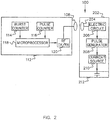
- FIG. 2 illustrates a block diagram of the system in accordance to the present invention.
- a typical microstimulator 100 or 102 comprises a biocompatible housing 202 having a coupling coil 204, an electrical circuitry 206 for power reception and data communication, a pulse generator 208 and current source 210 for providing electrical supply to the electrode 212 for stimulation.
- the controller 112 includes a burst counter 114, a pulse counter 116, a microprocessor 118, and an RF transmitter/receiver 120.
- the posterior portion of the GGM will be more capable of contracting forward thereby relieving the airway obstruction.
- each side of the GGM develops tone while there is a period of rest for the other side's GGM; this results in less chance of GGM fatigue. It is understood that a traditional approach of continuously stimulating and contracting only one side of the GGM results in muscle fatigue because the muscles require a relaxation period in order to allow blood circulation for oxygen and metabolic substances to reach the appropriate muscle fibers and for metabolic by-product to be removed.
- the alternating stimulation of the HGNs can be performed in equal or varying durations.
- the right HGN can be stimulated for a first predetermined period of time and the left HGN can be stimulated for a second predetermined period of time.
- Each HGN stimulation period can be concurrent or sequential and based on distinct inspiratory phases of the patient. For example, it is contemplated to stimulate the first HGN based on the first inspiratory phase and to stimulate the second HGN based on the second inspiratory phase.
- the first predetermined period of time and the second predetermined period of time can be partially overlapping in time.
- the stimulation duration of each HGN based on the inspiratory phase is about 5 seconds, which is produced by the burst counter 114 and communicated to the microprocessor 118.
- the frequency of the each stimulation pulse is the range of about 20 to 100 Hz (preferably about 30 Hz) and the pulse width is about 200 microseconds.
- the stimulation current is in the range of about 0.5 to 5 milliamps depending on the proximity of the microstimulator to the desired HGN.
- the pulse counter 116 generates approximately a 30 Hz signal for transmission to BION microstimulator.
- the microprocessor 118 communicates the desired stimulation pulsing data and power through the RF transmitter/receiver 120 via the coil 108 to the coupling coil 204 of the BION device.
- the stimulation timing of both HGNs can be either by a closed-loop feedback from sensors or an open-loop method.
- a patient's breathing pattern is monitored while asleep. The monitoring is accomplished either with another person present or through any known medical monitoring equipment that may be connected to the patient.
- the phase of the breathing cycle/ respiratory function of the patient may be monitored by a monitoring unit in the form of sensor such as a nasal flow probe 111, thermocouple, a pulse oxygen sensor, or with force sensitive bands on the thorax, or with any other monitoring means known to those skilled in the art.
- a determination is made as to the length and frequency of the patient's inspiratory effort/pattern. Having the aforementioned information available, then alternating stimulation to each HGN to cause alternating contraction of each side of the GGM according to the inspiratory pattern is performed.
- FIG. 3 is a flow chart of the steps of a method of treating OSA in a patient.
- the first microstimulator is provided proximate to the first HGN (302); and secondly, the second microstimulator is provided proximate to the second HGN (304).
- the first HGN is stimulated for a first predetermined length of time (306) and the second HGN is stimulated for a second predetermined length of time (308).
- stimulation of the first and the second HGNs are repeated as shown by a dotted line (310).
- a sensor or a group of sensors are utilized to monitor the patient's respiratory function similar to those sensors utilized in the open-loop method.
- the sensors can be any conventional sensors (e.g. those positioned on the nose or surface of the skin of the thorax/abdomen of a patient) capable of monitoring parameters of a patient indicative of the respiratory function.
- the respiratory function of the patient is monitored such that based on the determination of the inspiratory pattern one or both of the HGNs of the patient are stimulated.
- a feedback control signal is provided from the sensors monitoring the respiratory cycle/function of the patient to the controller, which in turn controls the operation of the stimulation function of the microstimulators.
- both microstimulators would stimulate the left and the right HGNs concurrently.
- each side would then need less contraction than when one side is used.
- This will be advantageous in providing a lower amount of stimulation current to each HGN than the total amount of stimulation current applied to a single HGN in a traditional OSA treatment, and possibly provide a more symmetrical opening of the pharynx.
- This mode of simultaneous HGN stimulation could be during inspiratory phases only or during both inspiratory and expiratory phases of a sleeping patient.
- the level of activity of the GGM is the same during sleep as it is during wakefulness.
- the level of activity of the GGM is increased approximately three times normal during wakefulness to compensate for their structurally small pharyngeal airway.
- individuals with OSA experience a large reduction in genioglossus activity from the elevated levels seen when they are awake.
- an afferent stimulation of the HGN is provided, which is set at a sub-motor threshold level.
- This is intended to cause an increase in the excitability of the hypoglossal nucleus (brain stem) resulting in an increase in firing of motor axons down the HGN producing an increase in tone of GGM muscles, thereby leading to a sustained increase in the pharyngeal airway and thus alleviating the main problem of OSA.
- the afferent fibers of the left and right HGN(s) are stimulated concurrently or in an alternate fashion.
- a motor-threshold level stimulation of the efferent fibers of the HGN(s) is provided as an excitatory input to the GGM(s). This is intended to produce an opening of the airway, thereby relieving an obstruction of the OSA.
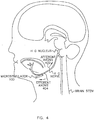
- FIG. 4 is an illustration of a microstimulator stimulating afferent and efferent fibers comprising the hypoglossal nerve originating in the brain stem hypoglossal nucleus and terminating in one side of the tongue's GGM.
- the microstimulator 100 can provide either an afferent stimulation (sub-motor threshold) or an efferent stimulation (at or above-motor threshold) to the respective afferent 402 and efferent 404 fibers (axons) of the HGN.
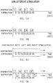
- FIG. 5A through FIG. 6B The various operations and stimulation methods according to the present invention are described below with reference to the relevant figures- FIG. 5A through FIG. 6B :
- the HGNs are stimulated at efferent stimulation level by alternating between left and right HGNs during the inspiratory phases of the patient.
- the HGNs are stimulated at efferent stimulation level by stimulating both left and right HGNs concurrently during the inspiratory phases of the patient.
- the HGNs are stimulated continuously at efferent stimulation level by stimulating both left and right HGNs concurrently during the inspiratory and expiratory phases of the patient.
- the HGNs are stimulated continuously at efferent stimulation level by alternately stimulating the left and then the right HGNs during the inspiratory and expiratory phases of the patient and vice versa.
- the HGNs are stimulated continuously at afferent stimulation level by stimulating both left and right HGNs concurrently during the inspiratory and expiratory phases of the patient.
- the HGNs are stimulated continuously at afferent stimulation level by alternately stimulating the left and then the right HGNs during the inspiratory and expiratory phases of the patient and vice versa.
- FIG. 7 is a side view of a portion of a human anatomy showing the inside of the human mouth and schematically showing the positioning of a microstimulator close to one of the HGNs.
- the microstimulator can be positioned in the intended location using an anterior approach path.
Description
- The present invention is generally directed to the application of implantable medical devices in treating physical dysfunctions, and more particularly to method and system for treatment of Obstructive Sleep Apnea (OSA).
- Obstructive sleep apnea (OSA) is a common disorder, estimated to affect 4% of middle-aged men and 2% of women. This disorder is characterized by recurrent pharyngeal collapse during sleep leading to repetitive arousals and nocturnal hypoxemia. OSA occurs in individuals with an anatomically small pharyngeal airway. Because of sleep-induced decreases in upper airway muscle tone, the airway collapses necessitating brief arousals from sleep to re-establish airway patency. These recurrent arousals result in sleep fragmentation, excessive daytime sleepiness and decreased quality of life. In addition, the arousals and the nocturnal hypoxemia result in catecholamine surges. Furthermore, there is accumulating evidence that adverse cardiovascular sequelae such as hypertension, arrhythmias, cerebrovascular events, myocardial infarction, and congestive heart failure may result from OSA.
- Current methods of therapy are aimed at splinting the airway open during sleep (Continuous Positive Airway Pressure: CPAP) or enlarging the pharyngeal airway through surgery or the use of oral appliances. Nasal CPAP is the most effective and most widely used therapy for obstructive sleep apnea. However, acceptance of and compliance with CPAP creates limitations for its use. Compliance with CPAP is generally reported to be in the range of 50 to 85%. Patients who abandon CPAP therapy typically do so during the first 2 to 4 weeks of treatment because of issues related to mask discomfort, nasal dryness and congestion, and difficulty adapting to the pressure.
- Studies demonstrate that compliance with CPAP is poor, although it can be improved with consistent follow-up (e.g. support groups) and when the patient's disease is severe. Untreated, patients with obstructive sleep apnea are at risk of negative sequelae. Thus, there exists a need for an alternative to CPAP for patients with obstructive sleep apnea.
-
US 6164284 describes a system for treating various conditions using nerve stimulation, the system including a plurality of microstimulators. -
-
FIG. 1 is an illustration of a system associated with a patient for treating OSA in accordance with the present invention. -
FIG. 2 is an illustration of a block diagram of the system in accordance to the present invention. -
FIG. 3 is a flow chart of the steps of a method of treating OSA in a patient. -
FIG. 4 is an illustration of a microstimulator stimulating afferent and efferent fibers comprising the hypoglossal nerve originating in the brain stem and terminating in the tongue muscle in accordance to the present invention. -
FIG. 5A is an illustration of alternating between left and right HGN efferent stimulation during inspiratory phases of a patient according to the present invention. -
FIG. 5B is an illustration of both HGN efferent stimulation during inspiratory phases of a patient according to the present invention. -
FIG. 5C is an illustration of both HGN efferent stimulation continuously during both inspiratory and expiratory phases of a patient according to the present invention. -
FIG. 5D is an illustration of alternating between left and right but continuous HGN efferent stimulation during both inspiratory and expiratory phases of a patient according to the present invention. -
FIG. 6A is an illustration of both HGN afferent stimulation continuously during both inspiratory and expiratory phases of a patient according to the present invention. -
FIG. 6 B is an illustration of alternating between left and right but continuous HGN afferent stimulation during both inspiratory and expiratory phases of a patient according to the present invention. -
FIG. 7 is a side view of a portion of a human anatomy showing the inside of the human mouth and schematically showing the positioning of a microstimulator close to one of the hypoglossal nerves. - The following description is of the best mode presently contemplated for carrying out the invention which is defined in
claim 1. Methods disclosed hereinafter do not form part of the scope of the invention. - This description is not to be taken in a limiting sense, but is made merely for the purpose of describing the general principles of the invention. The scope of the invention should be determined with reference to the claims.
- The present invention provides a system for treating OSA in a patient. As shown in
FIG. 1 , a patient exhibiting OSA is implanted with a pair of microstimulators, which are controllably activated to stimulate the left and right hypoglossal nerves (HGN) of the patient. It is known that traditionally a single electrode in the form of a nerve cuff electrode, percutaneous intramuscular motor-point electrode or implanted microstimulator has been used to stimulate only one of the HGNs or its motor-point in the genioglossus muscles (GGM) in a patient to cause the movement of the tongue in a desired direction in order to open the obstructed air way of a patient with OSA condition. The present invention contemplates providing one microstimulator implanted adjacent to each HGN in order to stimulate each HGN individually. There can be significant benefits in treating patients with OSA by providing one microstimulator adjacent to each left and right HGN. - As indicated above, the present invention is directed to a system for treating sleep apnea, and more particularly OSA using at least two small implantable microstimulators, also referred to as BION™ devices. Various features and details associated with the manufacture, operation and use of such implantable microstimulators, or BION devices, may be found in one or more of the following documents, all of which are incorporated herein by reference:
U.S. Pat. No. 5,193,539 entitled "Implantable Microstimulator";U.S. Pat. No. 5,193,540 , entitled "Structure and Method of Manufacture of an Implantable Microstimulator";U.S. Pat. No. 5,312,439 entitled "Implantable Device Having an Electrolytic Storage Electrode";U.S. Pat. No. 6,164,284 , entitled "System of implantable devices for monitoring and/or affecting body parameters;U.S. Pat. No. 6,185,452 , entitled "Battery-powered patient implantable device";U.S. Pat. No. 6,208,894 , entitled "System of implantable devices for monitoring and/or affecting body parameters";U.S. Pat. No. 6,315,721 , entitled "System of implantable devices for monitoring and/or affecting body parameters";6,564,807 , entitled "System of implantable devices for monitoring and/or affecting body parameters". - Referring to
FIG. 1 , it illustrates the system for treating OSA in accordance with the present invention. A pair ofmicrostimulators 100 and 102 in the form of BION devices are subcutaneously provided proximate to the first andsecond HGNs data transmission coil 108 is placed in the vicinity of the neck or the chin of thepatient 110. Thecoil 108 is connected to thecontroller 112. Thecontroller 112 supplies the electrical power and data through thecoil 108 to themicrostimulators 100 and 102 via a wireless magnetic coupling. Furthermore, in the alternative, it is contemplated that the data communication can be effected via an electromagnetic coupling (not shown) of the microstimulators with the controller. -
FIG. 2 illustrates a block diagram of the system in accordance to the present invention. Referring toFIG. 2 , atypical microstimulator 100 or 102 comprises abiocompatible housing 202 having acoupling coil 204, anelectrical circuitry 206 for power reception and data communication, apulse generator 208 andcurrent source 210 for providing electrical supply to theelectrode 212 for stimulation. Thecontroller 112 includes aburst counter 114, apulse counter 116, amicroprocessor 118, and an RF transmitter/receiver 120. - By increasing the GGM tone using cyclic/alternating stimulation to the HGNs, the posterior portion of the GGM will be more capable of contracting forward thereby relieving the airway obstruction. By alternating the stimulation of the left and right HGNs, each side of the GGM develops tone while there is a period of rest for the other side's GGM; this results in less chance of GGM fatigue. It is understood that a traditional approach of continuously stimulating and contracting only one side of the GGM results in muscle fatigue because the muscles require a relaxation period in order to allow blood circulation for oxygen and metabolic substances to reach the appropriate muscle fibers and for metabolic by-product to be removed. The alternating stimulation of the HGNs can be performed in equal or varying durations. For example, the right HGN can be stimulated for a first predetermined period of time and the left HGN can be stimulated for a second predetermined period of time. Each HGN stimulation period can be concurrent or sequential and based on distinct inspiratory phases of the patient. For example, it is contemplated to stimulate the first HGN based on the first inspiratory phase and to stimulate the second HGN based on the second inspiratory phase. Furthermore, the first predetermined period of time and the second predetermined period of time can be partially overlapping in time.
- According to the present invention, the stimulation duration of each HGN based on the inspiratory phase is about 5 seconds, which is produced by the
burst counter 114 and communicated to themicroprocessor 118. Moreover, the frequency of the each stimulation pulse is the range of about 20 to 100 Hz (preferably about 30 Hz) and the pulse width is about 200 microseconds. The stimulation current is in the range of about 0.5 to 5 milliamps depending on the proximity of the microstimulator to the desired HGN. As shown inFIG. 2 , thepulse counter 116 generates approximately a 30 Hz signal for transmission to BION microstimulator. Themicroprocessor 118 communicates the desired stimulation pulsing data and power through the RF transmitter/receiver 120 via thecoil 108 to thecoupling coil 204 of the BION device. - The stimulation timing of both HGNs can be either by a closed-loop feedback from sensors or an open-loop method. In an embodiment of an open-loop method, a patient's breathing pattern is monitored while asleep. The monitoring is accomplished either with another person present or through any known medical monitoring equipment that may be connected to the patient. The phase of the breathing cycle/ respiratory function of the patient may be monitored by a monitoring unit in the form of sensor such as a
nasal flow probe 111, thermocouple, a pulse oxygen sensor, or with force sensitive bands on the thorax, or with any other monitoring means known to those skilled in the art. After the monitoring of the patient's breathing pattern, a determination is made as to the length and frequency of the patient's inspiratory effort/pattern. Having the aforementioned information available, then alternating stimulation to each HGN to cause alternating contraction of each side of the GGM according to the inspiratory pattern is performed. -
FIG. 3 is a flow chart of the steps of a method of treating OSA in a patient. Initially, the first microstimulator is provided proximate to the first HGN (302); and secondly, the second microstimulator is provided proximate to the second HGN (304). Thereafter, the first HGN is stimulated for a first predetermined length of time (306) and the second HGN is stimulated for a second predetermined length of time (308). In order to maintain the air passage open during the inspiration phase of the respiratory pattern of the patient, stimulation of the first and the second HGNs are repeated as shown by a dotted line (310). - In an embodiment of a closed-loop method, a sensor or a group of sensors are utilized to monitor the patient's respiratory function similar to those sensors utilized in the open-loop method. The sensors can be any conventional sensors (e.g. those positioned on the nose or surface of the skin of the thorax/abdomen of a patient) capable of monitoring parameters of a patient indicative of the respiratory function. Hence, utilizing the sensors the respiratory function of the patient is monitored such that based on the determination of the inspiratory pattern one or both of the HGNs of the patient are stimulated. A feedback control signal is provided from the sensors monitoring the respiratory cycle/function of the patient to the controller, which in turn controls the operation of the stimulation function of the microstimulators.
- In an aspect of the present invention, it is contemplated that instead of alternating/cycling, both microstimulators would stimulate the left and the right HGNs concurrently. When both sides of the GGMs contract at the same time, each side would then need less contraction than when one side is used. This will be advantageous in providing a lower amount of stimulation current to each HGN than the total amount of stimulation current applied to a single HGN in a traditional OSA treatment, and possibly provide a more symmetrical opening of the pharynx. This mode of simultaneous HGN stimulation could be during inspiratory phases only or during both inspiratory and expiratory phases of a sleeping patient.
- In normal individuals (i.e., non-apneic), the level of activity of the GGM is the same during sleep as it is during wakefulness. In individuals with OSA, the level of activity of the GGM is increased approximately three times normal during wakefulness to compensate for their structurally small pharyngeal airway. When asleep, individuals with OSA experience a large reduction in genioglossus activity from the elevated levels seen when they are awake. In the present invention, it is contemplated that an afferent stimulation of the HGN is provided, which is set at a sub-motor threshold level. This is intended to cause an increase in the excitability of the hypoglossal nucleus (brain stem) resulting in an increase in firing of motor axons down the HGN producing an increase in tone of GGM muscles, thereby leading to a sustained increase in the pharyngeal airway and thus alleviating the main problem of OSA.
- In the present invention, it is contemplated that the afferent fibers of the left and right HGN(s) are stimulated concurrently or in an alternate fashion. Furthermore, it is contemplated in the present invention that a motor-threshold level stimulation of the efferent fibers of the HGN(s) is provided as an excitatory input to the GGM(s). This is intended to produce an opening of the airway, thereby relieving an obstruction of the OSA.
-
FIG. 4 is an illustration of a microstimulator stimulating afferent and efferent fibers comprising the hypoglossal nerve originating in the brain stem hypoglossal nucleus and terminating in one side of the tongue's GGM. As shown inFIG. 4 , themicrostimulator 100 can provide either an afferent stimulation (sub-motor threshold) or an efferent stimulation (at or above-motor threshold) to therespective afferent 402 andefferent 404 fibers (axons) of the HGN. - The various operations and stimulation methods according to the present invention are described below with reference to the relevant figures-
FIG. 5A through FIG. 6B : - Referring to
FIG. 5A , it is contemplated that the HGNs are stimulated at efferent stimulation level by alternating between left and right HGNs during the inspiratory phases of the patient. - Referring to
FIG. 5B , it is contemplated that the HGNs are stimulated at efferent stimulation level by stimulating both left and right HGNs concurrently during the inspiratory phases of the patient. - Referring to
FIG. 5C , it is contemplated that the HGNs are stimulated continuously at efferent stimulation level by stimulating both left and right HGNs concurrently during the inspiratory and expiratory phases of the patient. - Referring to
FIG. 5D , it is contemplated that the HGNs are stimulated continuously at efferent stimulation level by alternately stimulating the left and then the right HGNs during the inspiratory and expiratory phases of the patient and vice versa. - Referring to
FIG. 6A , it is contemplated that the HGNs are stimulated continuously at afferent stimulation level by stimulating both left and right HGNs concurrently during the inspiratory and expiratory phases of the patient. - Referring to
FIG. 6B , it is contemplated that the HGNs are stimulated continuously at afferent stimulation level by alternately stimulating the left and then the right HGNs during the inspiratory and expiratory phases of the patient and vice versa. - It must be noted that the aforementioned operations and stimulation methods may be effected utilizing a closed-loop or an open-loop method as described above.
- For a more clear visualization of the positioning of the microstimulators with respect to the HGN,
FIG. 7 is presented.FIG. 7 is a side view of a portion of a human anatomy showing the inside of the human mouth and schematically showing the positioning of a microstimulator close to one of the HGNs. The microstimulator can be positioned in the intended location using an anterior approach path. - The descriptions of the invention, the specific details, and the drawings mentioned above, are not meant to limit the scope of the present invention. The present invention may be embodied in other specific forms without departing from its spirit or essential characteristics. The described embodiments are to be considered in all respects only as illustrative and not restrictive. The scope of the invention is, therefore, indicated by the appended claims rather than by the foregoing description. All changes, which come within the meaning and range of equivalency of the claims, are to be embraced within their scope.
Claims (14)
- A system for treating sleep apnea in a patient comprising:a first microstimulator adapted to stimulate a first hypoglossal nerve (HGN);a second microstimulator adapted to stimulate a second HGN; anda controller for controlling the stimulation function of the first and the second microstimulators;wherein the first microstimulator is adapted to stimulate the first HGN for a first predetermined length of time and the second microstimulator is adapted to stimulate the second HGN for a second predetermined length of time, and the first predetermined length of time and the second predetermined length of time occur sequentially or alternatingly.
- The system of claim 1, wherein each of the first and the second microstimulators are less than 60 mm in longitudinal and less than 6 mm in lateral dimension.
- The system of claim 1, or 2, wherein the first microstimulator and the second microstimulator are controlled by the controller through a wireless communication medium.
- The system of claim 3, wherein the wireless communication medium is electromagnetic communication.
- The system of claim 3, wherein the wireless communication medium is magnetic communication.
- The system of any one of claims 1 to 5, further comprising a monitoring unit for monitoring the respiratory function of the patient.
- The system of claim 6, wherein the monitoring unit includes at least one sensor.
- The system of claim 6 or 7 wherein the monitoring unit provides a feedback control signal to the controller for controlling the stimulation function of the first and the second microstimulators.
- The system of any one of claims 1 to 8, wherein the first microstimulator and the second microstimulator are adapted to provide stimulation at a sub-motor threshold afferent stimulation level.
- The system of any one of claims 1 to 9, wherein the first microstimulator and the second microstimulator are adapted to provide stimulation at a motor-threshold level.
- The system of claim 1 or any claim dependent on claim 1, wherein the first predetermined length of time and the second predetermined length of time can be partially overlapping in time.
- The system of claim 1 or any claim dependent on claim 1, wherein the first predetermined length of time is based on the first inspiratory phase of the patient.
- The system of claim 12, wherein the second predetermined length of time is based on the second inspiratory phase of the patient.
- The system of claim 1, wherein the sequential stimulation is performed continuously.
Applications Claiming Priority (2)
| Application Number | Priority Date | Filing Date | Title |
|---|---|---|---|
| US51224503P | 2003-10-17 | 2003-10-17 | |
| US512245P | 2003-10-17 |
Publications (2)
| Publication Number | Publication Date |
|---|---|
| EP1524007A1 EP1524007A1 (en) | 2005-04-20 |
| EP1524007B1 true EP1524007B1 (en) | 2017-03-01 |
Family
ID=34375600
Family Applications (1)
| Application Number | Title | Priority Date | Filing Date |
|---|---|---|---|
| EP04256377.5A Active EP1524007B1 (en) | 2003-10-17 | 2004-10-15 | System for treating sleep apnea |
Country Status (2)
| Country | Link |
|---|---|
| US (1) | US20050085874A1 (en) |
| EP (1) | EP1524007B1 (en) |
Families Citing this family (40)
| Publication number | Priority date | Publication date | Assignee | Title |
|---|---|---|---|---|
| US20080077192A1 (en) | 2002-05-03 | 2008-03-27 | Afferent Corporation | System and method for neuro-stimulation |
| US7680538B2 (en) * | 2005-03-31 | 2010-03-16 | Case Western Reserve University | Method of treating obstructive sleep apnea using electrical nerve stimulation |
| US7644714B2 (en) | 2005-05-27 | 2010-01-12 | Apnex Medical, Inc. | Devices and methods for treating sleep disorders |
| US7725195B2 (en) * | 2006-02-16 | 2010-05-25 | Imthera Medical, Inc. | RFID-based apparatus, system, and method for therapeutic treatment of obstructive sleep apnea |
| AU2012201366B8 (en) * | 2006-02-16 | 2015-08-06 | Imthera Medical, Inc. | An RFID based apparatus, system, and method for therapeutic treatment of a patient |
| US7650189B1 (en) | 2006-06-02 | 2010-01-19 | Pacesetter, Inc. | Techniques to maintain or alter upper airway patency |
| AU2007313319B2 (en) | 2006-10-13 | 2012-03-22 | Cyberonics, Inc. | Obstructive sleep apnea treatment devices, systems and methods |
| US8855771B2 (en) | 2011-01-28 | 2014-10-07 | Cyberonics, Inc. | Screening devices and methods for obstructive sleep apnea therapy |
| US9205262B2 (en) | 2011-05-12 | 2015-12-08 | Cyberonics, Inc. | Devices and methods for sleep apnea treatment |
| US9186511B2 (en) | 2006-10-13 | 2015-11-17 | Cyberonics, Inc. | Obstructive sleep apnea treatment devices, systems and methods |
| US9744354B2 (en) | 2008-12-31 | 2017-08-29 | Cyberonics, Inc. | Obstructive sleep apnea treatment devices, systems and methods |
| US9913982B2 (en) | 2011-01-28 | 2018-03-13 | Cyberonics, Inc. | Obstructive sleep apnea treatment devices, systems and methods |
| CA2697822A1 (en) * | 2007-10-09 | 2009-04-16 | Imthera Medical, Inc. | Apparatus, system, and method for selective stimulation |
| WO2010006218A2 (en) * | 2008-07-11 | 2010-01-14 | Don Headley | Sleep apnea device and method |
| JP5547200B2 (en) | 2008-10-01 | 2014-07-09 | インスパイア・メディカル・システムズ・インコーポレイテッド | Transvenous treatment to treat sleep apnea |
| BRPI0920548B8 (en) * | 2008-10-09 | 2021-06-22 | Imthera Medical Inc | device to control the position of a patient's tongue |
| AU2014253460B2 (en) * | 2008-10-09 | 2017-02-02 | Imthera Medical, Inc. | Method of stimulating a hypoglossal nerve for controlling the position of a patient's tongue |
| WO2010059839A2 (en) | 2008-11-19 | 2010-05-27 | Inspire Medical Systems, Inc. | Method of treating sleep disordered breathing |
| US9950166B2 (en) | 2009-10-20 | 2018-04-24 | Nyxoah SA | Acred implant unit for modulation of nerves |
| US10751537B2 (en) | 2009-10-20 | 2020-08-25 | Nyxoah SA | Arced implant unit for modulation of nerves |
| US9409013B2 (en) | 2009-10-20 | 2016-08-09 | Nyxoah SA | Method for controlling energy delivery as a function of degree of coupling |
| WO2011059531A1 (en) * | 2009-11-10 | 2011-05-19 | Imthera Medical, Inc. | System for stimulating a hypoglossal nerve for controlling the position of a patient's tongue |
| JP6092212B2 (en) | 2011-08-11 | 2017-03-08 | インスパイア・メディカル・システムズ・インコーポレイテッドInspire Medical Systems, Inc. | System for selecting a stimulation protocol based on detection results of respiratory effort |
| WO2013173214A1 (en) * | 2012-05-15 | 2013-11-21 | Imthera Medical, Inc. | Stimulation of a hypoglossal nerve for controlling the position of a patient's tongue |
| US9907967B2 (en) | 2012-07-26 | 2018-03-06 | Adi Mashiach | Transcutaneous power conveyance device |
| US10052097B2 (en) | 2012-07-26 | 2018-08-21 | Nyxoah SA | Implant unit delivery tool |
| BR112015001743A2 (en) | 2012-07-26 | 2017-07-04 | Mashiach Adi | implant encapsulation |
| US11253712B2 (en) | 2012-07-26 | 2022-02-22 | Nyxoah SA | Sleep disordered breathing treatment apparatus |
| US9308381B2 (en) | 2013-06-17 | 2016-04-12 | Nyxoah SA | Ceramic encapsulation of an implantable device |
| US11383083B2 (en) | 2014-02-11 | 2022-07-12 | Livanova Usa, Inc. | Systems and methods of detecting and treating obstructive sleep apnea |
| JP6759227B2 (en) | 2015-03-19 | 2020-09-23 | インスパイア・メディカル・システムズ・インコーポレイテッドInspire Medical Systems, Inc. | Stimulation to treat obstructive sleep apnea |
| EP4252833A3 (en) * | 2015-11-17 | 2023-11-15 | Inspire Medical Systems, Inc. | Microstimulation sleep disordered breathing (sdb) therapy device |
| CN109069821A (en) * | 2016-02-29 | 2018-12-21 | 加尔瓦尼生物电子有限公司 | Nerve modulation equipment |
| US11247039B2 (en) | 2016-05-03 | 2022-02-15 | Btl Healthcare Technologies A.S. | Device including RF source of energy and vacuum system |
| US10583287B2 (en) | 2016-05-23 | 2020-03-10 | Btl Medical Technologies S.R.O. | Systems and methods for tissue treatment |
| US10556122B1 (en) | 2016-07-01 | 2020-02-11 | Btl Medical Technologies S.R.O. | Aesthetic method of biological structure treatment by magnetic field |
| JP2021524772A (en) | 2018-06-01 | 2021-09-16 | ゼネア テクノロジーズ インコーポレイテツドZennea Technologies Inc. | Methods and Devices for Treating Sleep-Related Brain Disorders |
| US11878167B2 (en) | 2020-05-04 | 2024-01-23 | Btl Healthcare Technologies A.S. | Device and method for unattended treatment of a patient |
| CA3173876A1 (en) | 2020-05-04 | 2021-11-11 | Tomas SCHWARZ | Device and method for unattended treatment of a patient |
| US11896816B2 (en) | 2021-11-03 | 2024-02-13 | Btl Healthcare Technologies A.S. | Device and method for unattended treatment of a patient |
Family Cites Families (43)
| Publication number | Priority date | Publication date | Assignee | Title |
|---|---|---|---|---|
| JP2794196B2 (en) * | 1989-06-20 | 1998-09-03 | チェスト株式会社 | Apnea prevention stimulator |
| US5146918A (en) * | 1991-03-19 | 1992-09-15 | Medtronic, Inc. | Demand apnea control of central and obstructive sleep apnea |
| US5215082A (en) * | 1991-04-02 | 1993-06-01 | Medtronic, Inc. | Implantable apnea generator with ramp on generator |
| US5540733A (en) * | 1994-09-21 | 1996-07-30 | Medtronic, Inc. | Method and apparatus for detecting and treating obstructive sleep apnea |
| US5540731A (en) * | 1994-09-21 | 1996-07-30 | Medtronic, Inc. | Method and apparatus for pressure detecting and treating obstructive airway disorders |
| US5540732A (en) * | 1994-09-21 | 1996-07-30 | Medtronic, Inc. | Method and apparatus for impedance detecting and treating obstructive airway disorders |
| US5549655A (en) * | 1994-09-21 | 1996-08-27 | Medtronic, Inc. | Method and apparatus for synchronized treatment of obstructive sleep apnea |
| US5522862A (en) * | 1994-09-21 | 1996-06-04 | Medtronic, Inc. | Method and apparatus for treating obstructive sleep apnea |
| US5591216A (en) * | 1995-05-19 | 1997-01-07 | Medtronic, Inc. | Method for treatment of sleep apnea by electrical stimulation |
| US6198970B1 (en) * | 1995-10-27 | 2001-03-06 | Esd Limited Liability Company | Method and apparatus for treating oropharyngeal respiratory and oral motor neuromuscular disorders with electrical stimulation |
| US5891185A (en) * | 1995-10-27 | 1999-04-06 | Esd Limited Liability Company | Method and apparatus for treating oropharyngeal disorders with electrical stimulation |
| US6164284A (en) * | 1997-02-26 | 2000-12-26 | Schulman; Joseph H. | System of implantable devices for monitoring and/or affecting body parameters |
| US6251126B1 (en) * | 1998-04-23 | 2001-06-26 | Medtronic Inc | Method and apparatus for synchronized treatment of obstructive sleep apnea |
| WO2000006249A2 (en) * | 1998-07-27 | 2000-02-10 | Case Western Reserve University | Method and apparatus for closed-loop stimulation of the hypoglossal nerve in human patients to treat obstructive sleep apnea |
| US6240316B1 (en) * | 1998-08-14 | 2001-05-29 | Advanced Bionics Corporation | Implantable microstimulation system for treatment of sleep apnea |
| US7499742B2 (en) * | 2001-09-26 | 2009-03-03 | Cvrx, Inc. | Electrode structures and methods for their use in cardiovascular reflex control |
| US20020049479A1 (en) * | 2000-10-20 | 2002-04-25 | Pitts Walter C. | Method and apparatus for creating afferents to prevent obstructive sleep apnea |
| US6641542B2 (en) * | 2001-04-30 | 2003-11-04 | Medtronic, Inc. | Method and apparatus to detect and treat sleep respiratory events |
| US20060167498A1 (en) * | 2001-07-23 | 2006-07-27 | Dilorenzo Daniel J | Method, apparatus, and surgical technique for autonomic neuromodulation for the treatment of disease |
| US6928324B2 (en) * | 2002-02-14 | 2005-08-09 | Pacesetter, Inc. | Stimulation device for sleep apnea prevention, detection and treatment |
| US20030195571A1 (en) * | 2002-04-12 | 2003-10-16 | Burnes John E. | Method and apparatus for the treatment of central sleep apnea using biventricular pacing |
| US6881192B1 (en) * | 2002-06-12 | 2005-04-19 | Pacesetter, Inc. | Measurement of sleep apnea duration and evaluation of response therapies using duration metrics |
| US7438686B2 (en) * | 2003-01-10 | 2008-10-21 | Medtronic, Inc. | Apparatus and method for monitoring for disordered breathing |
| US7319899B2 (en) * | 2003-04-23 | 2008-01-15 | Medtronic, Inc. | Sensing techniques for implantable medical devices |
| WO2005004986A1 (en) * | 2003-07-10 | 2005-01-20 | Jms Co.,Ltd. | Pacemaker system for treating sleep apnea syndrome |
| US7680537B2 (en) * | 2003-08-18 | 2010-03-16 | Cardiac Pacemakers, Inc. | Therapy triggered by prediction of disordered breathing |
| US7967756B2 (en) * | 2003-09-18 | 2011-06-28 | Cardiac Pacemakers, Inc. | Respiratory therapy control based on cardiac cycle |
| US20060167523A1 (en) * | 2003-10-15 | 2006-07-27 | Tehrani Amir J | Device and method for improving upper airway functionality |
| US8467876B2 (en) * | 2003-10-15 | 2013-06-18 | Rmx, Llc | Breathing disorder detection and therapy delivery device and method |
| US7130687B2 (en) * | 2003-10-24 | 2006-10-31 | Medtronic, Inc | Implantable medical device and method for delivering therapy for sleep-disordered breathing |
| US7184817B2 (en) * | 2003-12-19 | 2007-02-27 | Cardiac Pacemakers, Inc. | System and method for acquiring breathing pattern signals from intracardiac electrograms and its use for heart failure therapy decision making and disease monitoring |
| US7215997B2 (en) * | 2003-12-22 | 2007-05-08 | Cardiac Pacemakers, Inc. | Dynamic device therapy control for treating post myocardial infarction patients |
| US7225021B1 (en) * | 2004-01-30 | 2007-05-29 | Pacesetter, Inc. | Differentiation of central sleep apnea and obstructive sleep apnea using an implantable cardiac device |
| US7697990B2 (en) * | 2004-02-20 | 2010-04-13 | Resmed Limited | Method and apparatus for detection and treatment of respiratory disorder by implantable device |
| US20070213782A1 (en) * | 2004-03-18 | 2007-09-13 | Shaw David P | Method and Apparatus for the Treatment of Sleep Apnea and Snoring |
| US7245971B2 (en) * | 2004-04-21 | 2007-07-17 | Pacesetter, Inc. | System and method for applying therapy during hyperpnea phase of periodic breathing using an implantable medical device |
| US20060058852A1 (en) * | 2004-09-10 | 2006-03-16 | Steve Koh | Multi-variable feedback control of stimulation for inspiratory facilitation |
| US7269459B1 (en) * | 2005-02-08 | 2007-09-11 | Pacesetter, Inc. | Implantable cardiac device with selectable tiered sleep apnea therapies and method |
| US7680538B2 (en) * | 2005-03-31 | 2010-03-16 | Case Western Reserve University | Method of treating obstructive sleep apnea using electrical nerve stimulation |
| US20060241708A1 (en) * | 2005-04-22 | 2006-10-26 | Willem Boute | Multiple sensors for sleep apnea with probability indication for sleep diagnosis and means for automatic activation of alert or therapy |
| US7751884B2 (en) * | 2005-04-28 | 2010-07-06 | Cardiac Pacemakers, Inc. | Flexible neural stimulation engine |
| CA2865410C (en) * | 2005-11-18 | 2022-04-26 | Mark Gelfand | System and method to modulate phrenic nerve to prevent sleep apnea |
| WO2007147046A2 (en) * | 2006-06-14 | 2007-12-21 | Zmed Technologies, Inc. | Respiration stimulation |
-
2004
- 2004-10-14 US US10/966,629 patent/US20050085874A1/en not_active Abandoned
- 2004-10-15 EP EP04256377.5A patent/EP1524007B1/en active Active
Non-Patent Citations (1)
| Title |
|---|
| None * |
Also Published As
| Publication number | Publication date |
|---|---|
| US20050085874A1 (en) | 2005-04-21 |
| EP1524007A1 (en) | 2005-04-20 |
Similar Documents
| Publication | Publication Date | Title |
|---|---|---|
| EP1524007B1 (en) | System for treating sleep apnea | |
| US11647947B2 (en) | Method for adjusting a system for stimulating a hypoglossal nerve | |
| JP4679464B2 (en) | Inner ear vestibular stimulator | |
| US7469162B2 (en) | Vestibular stimulation system and method | |
| US8160711B2 (en) | Multimode device and method for controlling breathing | |
| US7979128B2 (en) | Device and method for gradually controlling breathing | |
| US9370657B2 (en) | Device for manipulating tidal volume and breathing entrainment | |
| CA2738479C (en) | Method of stimulating a hypoglossal nerve for controlling the position of a patient's tongue | |
| JP7384932B2 (en) | Methods and systems for electrical nerve stimulation | |
| Salah et al. | Obstructive Sleep Apnea treatment Methods: A Comparative Study | |
| AU2002301815B2 (en) | Vesibular stimulation system and method |
Legal Events
| Date | Code | Title | Description |
|---|---|---|---|
| PUAI | Public reference made under article 153(3) epc to a published international application that has entered the european phase |
Free format text: ORIGINAL CODE: 0009012 |
|
| AK | Designated contracting states |
Kind code of ref document: A1 Designated state(s): AT BE BG CH CY CZ DE DK EE ES FI FR GB GR HU IE IT LI LU MC NL PL PT RO SE SI SK TR |
|
| AX | Request for extension of the european patent |
Extension state: AL HR LT LV MK |
|
| 17P | Request for examination filed |
Effective date: 20050623 |
|
| AKX | Designation fees paid |
Designated state(s): AT BE BG CH CY CZ DE DK EE ES FI FR GB GR HU IE IT LI LU MC NL PL PT RO SE SI SK TR |
|
| 17Q | First examination report despatched |
Effective date: 20110404 |
|
| GRAP | Despatch of communication of intention to grant a patent |
Free format text: ORIGINAL CODE: EPIDOSNIGR1 |
|
| INTG | Intention to grant announced |
Effective date: 20160426 |
|
| GRAJ | Information related to disapproval of communication of intention to grant by the applicant or resumption of examination proceedings by the epo deleted |
Free format text: ORIGINAL CODE: EPIDOSDIGR1 |
|
| INTC | Intention to grant announced (deleted) | ||
| GRAP | Despatch of communication of intention to grant a patent |
Free format text: ORIGINAL CODE: EPIDOSNIGR1 |
|
| INTG | Intention to grant announced |
Effective date: 20161010 |
|
| GRAS | Grant fee paid |
Free format text: ORIGINAL CODE: EPIDOSNIGR3 |
|
| GRAA | (expected) grant |
Free format text: ORIGINAL CODE: 0009210 |
|
| AK | Designated contracting states |
Kind code of ref document: B1 Designated state(s): AT BE BG CH CY CZ DE DK EE ES FI FR GB GR HU IE IT LI LU MC NL PL PT RO SE SI SK TR |
|
| REG | Reference to a national code |
Ref country code: GB Ref legal event code: FG4D |
|
| REG | Reference to a national code |
Ref country code: CH Ref legal event code: EP Ref country code: AT Ref legal event code: REF Ref document number: 870570 Country of ref document: AT Kind code of ref document: T Effective date: 20170315 |
|
| REG | Reference to a national code |
Ref country code: IE Ref legal event code: FG4D |
|
| REG | Reference to a national code |
Ref country code: DE Ref legal event code: R096 Ref document number: 602004050820 Country of ref document: DE |
|
| REG | Reference to a national code |
Ref country code: NL Ref legal event code: MP Effective date: 20170301 |
|
| REG | Reference to a national code |
Ref country code: AT Ref legal event code: MK05 Ref document number: 870570 Country of ref document: AT Kind code of ref document: T Effective date: 20170301 |
|
| PG25 | Lapsed in a contracting state [announced via postgrant information from national office to epo] |
Ref country code: GR Free format text: LAPSE BECAUSE OF FAILURE TO SUBMIT A TRANSLATION OF THE DESCRIPTION OR TO PAY THE FEE WITHIN THE PRESCRIBED TIME-LIMIT Effective date: 20170602 Ref country code: FI Free format text: LAPSE BECAUSE OF FAILURE TO SUBMIT A TRANSLATION OF THE DESCRIPTION OR TO PAY THE FEE WITHIN THE PRESCRIBED TIME-LIMIT Effective date: 20170301 |
|
| PG25 | Lapsed in a contracting state [announced via postgrant information from national office to epo] |
Ref country code: AT Free format text: LAPSE BECAUSE OF FAILURE TO SUBMIT A TRANSLATION OF THE DESCRIPTION OR TO PAY THE FEE WITHIN THE PRESCRIBED TIME-LIMIT Effective date: 20170301 Ref country code: BG Free format text: LAPSE BECAUSE OF FAILURE TO SUBMIT A TRANSLATION OF THE DESCRIPTION OR TO PAY THE FEE WITHIN THE PRESCRIBED TIME-LIMIT Effective date: 20170601 Ref country code: SE Free format text: LAPSE BECAUSE OF FAILURE TO SUBMIT A TRANSLATION OF THE DESCRIPTION OR TO PAY THE FEE WITHIN THE PRESCRIBED TIME-LIMIT Effective date: 20170301 Ref country code: ES Free format text: LAPSE BECAUSE OF FAILURE TO SUBMIT A TRANSLATION OF THE DESCRIPTION OR TO PAY THE FEE WITHIN THE PRESCRIBED TIME-LIMIT Effective date: 20170301 |
|
| PG25 | Lapsed in a contracting state [announced via postgrant information from national office to epo] |
Ref country code: NL Free format text: LAPSE BECAUSE OF FAILURE TO SUBMIT A TRANSLATION OF THE DESCRIPTION OR TO PAY THE FEE WITHIN THE PRESCRIBED TIME-LIMIT Effective date: 20170301 |
|
| PG25 | Lapsed in a contracting state [announced via postgrant information from national office to epo] |
Ref country code: RO Free format text: LAPSE BECAUSE OF FAILURE TO SUBMIT A TRANSLATION OF THE DESCRIPTION OR TO PAY THE FEE WITHIN THE PRESCRIBED TIME-LIMIT Effective date: 20170301 Ref country code: EE Free format text: LAPSE BECAUSE OF FAILURE TO SUBMIT A TRANSLATION OF THE DESCRIPTION OR TO PAY THE FEE WITHIN THE PRESCRIBED TIME-LIMIT Effective date: 20170301 Ref country code: IT Free format text: LAPSE BECAUSE OF FAILURE TO SUBMIT A TRANSLATION OF THE DESCRIPTION OR TO PAY THE FEE WITHIN THE PRESCRIBED TIME-LIMIT Effective date: 20170301 Ref country code: SK Free format text: LAPSE BECAUSE OF FAILURE TO SUBMIT A TRANSLATION OF THE DESCRIPTION OR TO PAY THE FEE WITHIN THE PRESCRIBED TIME-LIMIT Effective date: 20170301 Ref country code: CZ Free format text: LAPSE BECAUSE OF FAILURE TO SUBMIT A TRANSLATION OF THE DESCRIPTION OR TO PAY THE FEE WITHIN THE PRESCRIBED TIME-LIMIT Effective date: 20170301 |
|
| PG25 | Lapsed in a contracting state [announced via postgrant information from national office to epo] |
Ref country code: PT Free format text: LAPSE BECAUSE OF FAILURE TO SUBMIT A TRANSLATION OF THE DESCRIPTION OR TO PAY THE FEE WITHIN THE PRESCRIBED TIME-LIMIT Effective date: 20170703 Ref country code: PL Free format text: LAPSE BECAUSE OF FAILURE TO SUBMIT A TRANSLATION OF THE DESCRIPTION OR TO PAY THE FEE WITHIN THE PRESCRIBED TIME-LIMIT Effective date: 20170301 |
|
| REG | Reference to a national code |
Ref country code: DE Ref legal event code: R097 Ref document number: 602004050820 Country of ref document: DE |
|
| PLBE | No opposition filed within time limit |
Free format text: ORIGINAL CODE: 0009261 |
|
| STAA | Information on the status of an ep patent application or granted ep patent |
Free format text: STATUS: NO OPPOSITION FILED WITHIN TIME LIMIT |
|
| PG25 | Lapsed in a contracting state [announced via postgrant information from national office to epo] |
Ref country code: DK Free format text: LAPSE BECAUSE OF FAILURE TO SUBMIT A TRANSLATION OF THE DESCRIPTION OR TO PAY THE FEE WITHIN THE PRESCRIBED TIME-LIMIT Effective date: 20170301 |
|
| 26N | No opposition filed |
Effective date: 20171204 |
|
| PG25 | Lapsed in a contracting state [announced via postgrant information from national office to epo] |
Ref country code: SI Free format text: LAPSE BECAUSE OF FAILURE TO SUBMIT A TRANSLATION OF THE DESCRIPTION OR TO PAY THE FEE WITHIN THE PRESCRIBED TIME-LIMIT Effective date: 20170301 |
|
| PG25 | Lapsed in a contracting state [announced via postgrant information from national office to epo] |
Ref country code: MC Free format text: LAPSE BECAUSE OF FAILURE TO SUBMIT A TRANSLATION OF THE DESCRIPTION OR TO PAY THE FEE WITHIN THE PRESCRIBED TIME-LIMIT Effective date: 20170301 |
|
| REG | Reference to a national code |
Ref country code: CH Ref legal event code: PL |
|
| REG | Reference to a national code |
Ref country code: IE Ref legal event code: MM4A |
|
| REG | Reference to a national code |
Ref country code: FR Ref legal event code: ST Effective date: 20180629 |
|
| PG25 | Lapsed in a contracting state [announced via postgrant information from national office to epo] |
Ref country code: LI Free format text: LAPSE BECAUSE OF NON-PAYMENT OF DUE FEES Effective date: 20171031 Ref country code: LU Free format text: LAPSE BECAUSE OF NON-PAYMENT OF DUE FEES Effective date: 20171015 Ref country code: CH Free format text: LAPSE BECAUSE OF NON-PAYMENT OF DUE FEES Effective date: 20171031 |
|
| REG | Reference to a national code |
Ref country code: BE Ref legal event code: MM Effective date: 20171031 |
|
| PG25 | Lapsed in a contracting state [announced via postgrant information from national office to epo] |
Ref country code: BE Free format text: LAPSE BECAUSE OF NON-PAYMENT OF DUE FEES Effective date: 20171031 Ref country code: FR Free format text: LAPSE BECAUSE OF NON-PAYMENT OF DUE FEES Effective date: 20171031 |
|
| PG25 | Lapsed in a contracting state [announced via postgrant information from national office to epo] |
Ref country code: IE Free format text: LAPSE BECAUSE OF NON-PAYMENT OF DUE FEES Effective date: 20171015 |
|
| PG25 | Lapsed in a contracting state [announced via postgrant information from national office to epo] |
Ref country code: HU Free format text: LAPSE BECAUSE OF FAILURE TO SUBMIT A TRANSLATION OF THE DESCRIPTION OR TO PAY THE FEE WITHIN THE PRESCRIBED TIME-LIMIT; INVALID AB INITIO Effective date: 20041015 |
|
| PG25 | Lapsed in a contracting state [announced via postgrant information from national office to epo] |
Ref country code: CY Free format text: LAPSE BECAUSE OF NON-PAYMENT OF DUE FEES Effective date: 20170301 |
|
| PG25 | Lapsed in a contracting state [announced via postgrant information from national office to epo] |
Ref country code: TR Free format text: LAPSE BECAUSE OF FAILURE TO SUBMIT A TRANSLATION OF THE DESCRIPTION OR TO PAY THE FEE WITHIN THE PRESCRIBED TIME-LIMIT Effective date: 20170301 |
|
| PGFP | Annual fee paid to national office [announced via postgrant information from national office to epo] |
Ref country code: GB Payment date: 20231027 Year of fee payment: 20 |
|
| PGFP | Annual fee paid to national office [announced via postgrant information from national office to epo] |
Ref country code: DE Payment date: 20231027 Year of fee payment: 20 |