EP1523902A1 - Piercing apparatus for piercing a small compressed gas bottle to quickly inflate a sack and tool for reloading the piercing apparatus - Google Patents
Piercing apparatus for piercing a small compressed gas bottle to quickly inflate a sack and tool for reloading the piercing apparatus Download PDFInfo
- Publication number
- EP1523902A1 EP1523902A1 EP04425766A EP04425766A EP1523902A1 EP 1523902 A1 EP1523902 A1 EP 1523902A1 EP 04425766 A EP04425766 A EP 04425766A EP 04425766 A EP04425766 A EP 04425766A EP 1523902 A1 EP1523902 A1 EP 1523902A1
- Authority
- EP
- European Patent Office
- Prior art keywords
- piercing
- gas bottle
- protuberance
- collet
- compressed gas
- Prior art date
- Legal status (The legal status is an assumption and is not a legal conclusion. Google has not performed a legal analysis and makes no representation as to the accuracy of the status listed.)
- Granted
Links
- 230000005540 biological transmission Effects 0.000 claims abstract description 13
- 239000000463 material Substances 0.000 description 3
- 230000000717 retained effect Effects 0.000 description 3
- 230000000694 effects Effects 0.000 description 1
- 238000012986 modification Methods 0.000 description 1
- 230000004048 modification Effects 0.000 description 1
- 239000002699 waste material Substances 0.000 description 1
Images


Classifications
-
- A—HUMAN NECESSITIES
- A45—HAND OR TRAVELLING ARTICLES
- A45C—PURSES; LUGGAGE; HAND CARRIED BAGS
- A45C13/00—Details; Accessories
- A45C13/18—Devices to prevent theft or loss of purses, luggage or hand carried bags
- A45C13/24—Devices for sound-producing, piercing, gas-discharging, or the like
Definitions
- This invention relates to a piercing apparatus for piercing a small compressed gas bottle to quickly inflate a sack. Further the invention concerns a tool for reloading the piercing apparatus.
- Such a device comprises an expandable sack which is arranged on the bottom of a bag below its lining.
- the expandable sack is connected to a small compressed gas bottle having a pierceable mouth so that the expandable sack is able to be inflated from a wait condition wherein it is empty to an operated state wherein the expandable sack is inflated to a volume greater than the internal volume of the bag.
- a housing which is connected to the small compressed gas bottle and to the expandable sack, internally carries a piercing element provided with an axial passageway communicating with the expandable sack through a hollow cylindrical body thereof which is movable under a pre-charged spring.
- a release mechanism of the pre-charged spring to push the piercing element is provided.
- the release mechanism has an ogival release member that is in engagement with the piercing element through small balls.
- a control member of the release mechanism comprises a Bowden cable transmission, that is removably retained by a thin plate in the one of its ends near its connection to the ogival release member, and in the other one of its ends a junction member to a portion of the bag designed to be held permanently by who wears the bag, such as a handle or a shoulder-strap.
- a snatch being transmitted to the handle or to the shoulder-strap through the Bowden cable transmission, operates the release mechanism and causes the expandable sack to be inflated until the lining is completely overturned outside and a complete ejection of the contents from the bag occurs.
- a first drawback of said patent is that the thin plate retaining the cable transmission of the control member, as the thin plate is easily deformable, is not a means adapted to prevent reliably an undesirable operation of the ejection of the contents in a bag.
- a second drawback of the ejection device according to said patent is that a resetting of its release mechanism is troublesome to be performed and causes waste of time.
- a third drawback is that in the known ejection device said resetting must be performed by a skilled worker who can use suitable tools.
- the object of the present invention is to overcome the above mentioned drawbacks.
- an object of the present invention is to provide a reliable operation of the ejection of the contents in a bag in which such a safety device against the bag-snatching is installed.
- Another object of the invention is to allow a quick and reliable resetting of the release mechanism that is used in such an ejection device.
- Yet another object of the invention is that there is no need of a skilled worker to reset of the release mechanism that is used in such an ejection device.
- a further object of the present invention is to provide a release mechanism that causes a small compressed gas bottle, that is used in different applications from an ejection device of a self-emptying bag, to be pierced.
- a piercing apparatus for piercing a small compressed gas bottle to quickly inflate a sack, comprising:
- the invention concerns a tool for reloading the piercing apparatus.
- a piercing apparatus according to the invention is shown as a whole in Figs. 1 and 2 in a wait condition and in an operated state, respectively.
- such a piercing apparatus can be employed in a self-emptying bag 100, which is depicted by dotted lines in a closed condition (Fig. 7) and in a following consequently opened condition (Fig. 8).
- the bag 100 is endowed with a shoulder-strap 200.
- the bag 100 is provided with a folding cover 101.
- closure means of the folding cover 101 that is diagrammatically shown in 300, it can be of any suitable kind, such as press-stud, Velcro (trade name) or the like, provided that it is yielding under the action of an ejection device, using the piercing apparatus according to the invention, in order to allow the bag to be opened and its contents to fall down.
- the bag 100 is lined inside by a lining 400 shaped as a pocket that is preferably held, although this is not shown in the drawing, in its upper hem by the edge of the bag in a removable way, e.g. by means of a zip or so called Velcro.
- a lining 400 shaped as a pocket that is preferably held, although this is not shown in the drawing, in its upper hem by the edge of the bag in a removable way, e.g. by means of a zip or so called Velcro.
- the bottle piercing apparatus according to the invention is located in the space 401.
- the airtight expandable sack 1 as diagrammatically depicted in its collapsed state in Fig. 7, is arranged in a collected way, e.g. folded, under the lining 400.
- Fig. 8 the expandable sack l'takes on the form of a prismatic body, so to be able to keep the lining 400 overturned in 400' as shown in the same figures.
- connection duct 10 At the bottom the expandable sack 1 is hermetically connected through connection duct 10 to an elongated housing 20 of a compressed gas feeder 2.
- the elongated housing 20 can be made of a suitable plastic material.
- the compressed gas feeder 2 is located below the expandable sack 1, being preferably arranged between restraint panels 5 e.g. of a suitable foamy plastic material, in order to prevent the compressed gas 2 from wandering troublesomely on the base 102 of the bag.
- Fig.1 which is a longitudinal section view of the compressed gas feeder 2, the generally cylindrical, elongated housing 20 thereof, whose inner chamber 21 is in communication with the expandable sack 1, frontally carries a small bottle 6 of compressed air or other gas and, in a sequence from an end to the other end thereof, a spring-charged piercing element 7 and a release mechanism 8.
- the small gas bottle 6 having a pierceable sealed mouth 60, is screwed to the elongated housing 20 by means of its externally threaded neck 61.
- the small gas bottle has such a capacity that the expandable sack 1, after being inflated instantaneously, is able with its expansion to exert a sufficient force to expel objects contained inside the bag 100 between the lining 400 and the bag cover 101 upon the opening of the closure means and the overturning of the cover.
- the gas bottle 6 is closed in its mouth 60 by a septum that is easily pierceable by the piercing element 7 provided with a piercing bit 72.
- the piercing bit 72 preferably as a mouthpiece of a flute, is shaped so that the cut portion of septum remains in part laterally attached to the septum, without obstructing the emission of gas.
- the piercing bit 72 has an axial passageway 73.
- the release mechanism 8, which pushes the piercing element 7 against the gas bottle 6, comprises a release member being connected to a flexible transmission 30 of control means 3, e.g. the control means of a self-emptying bag in Figs. 7 and 8.
- such a release member is a protuberance 87, that is slidable in the inner chamber 21 of the elongated housing 20 by the operation of the flexible transmission 30 against a counteracting spring 89.
- the protuberance 87 is rigidly connected to a cylindrical element 83 that is provided with at least a pair of opposed tooth 84. These tooth 84 are designed to slide on grooves 85 that are provided in the inner chamber 21 of the elongated housing 20.
- the piercing element 7 is fixed to one end of a collet chuck 70, which, at the other end, is provided with fingers 88 to grip the protuberance 87 of the release mechanism 8.
- the collet chuck 70 is very similar to that one of a propelling pencil and can be made of plastic material.
- the collet chuck 70 being movable between a gripping condition (Fig. 1) and a releasing condition of the protuberance 87 (Fig. 2), is slidable coaxially with respect to an external cam profile 90 surrounding at least the fingers 88 under the action of a spiral spring 91.
- the spiral spring 91 is abutted between a flange 92 of the front end of the collet chuck 70 and the external cam profile 90.
- the external cam profile 90 that is in abutment against an internal circumferential projection 93 of the inner chamber 21 of the elongated housing 20, has an internal space 94, that is preferably cylindrical, with a consecutive frusto-conical portion 95. Then, such an internal space is adapted to receive and retain the fingers 88 of the collet chuck 70 in engagement with the protuberance 87 against the slide of the same collet chuck 70.
- the control means 3 which is generally a Bowden cable
- its flexible transmission 30 being connected to the protuberance 87
- the protuberance 87 slides, by virtue of its tooth 84 engaging the grooves 85 of the inner chamber 21 of the elongated housing 20 against the action of the counteracting spring 89.
- the protuberance 87 loses the engagement with the fingers 88 of the collet chuck 70.
- the fingers for example four in number, being retained no longer by the protuberance 87 against the cylindrical-frustoconical space 94-95 of the cam profile 90, are able to pass through the cylindrical portion 94 of said space 94-95.
- the collet chuck 70 that is pushed by the spring 91 in abutment between the flange 92 of the same collet chuck 70 and the cam profile 90, is obliged to travel suddenly toward the front end of the elongated housing 20, where the small gas bottle 6 is screwed.
- the expandable sack 1 is inflated immediately.
- a seal gasket 99 being situated around the connection with the flexible transmission 30 of the release element, is provided.
- the reloading tool has an elongated cylindrical body, including a maximum diameter, first section 50, an intermediate diameter, second section 51, and a minimum diameter, third section 52.
- the maximum diameter, first section 50 is internally hollow and is provided with an internal thread for screwing onto the threaded neck of the gas bottle 6.
- the second section 51 that is externally threaded, has a diameter equal to that of the neck of the gas bottle 6 with same thread.
- the minimum diameter, internally hollow, third section 52 is such that it surrounds the piercing element 7.
- the section 52 of the tool causes the collet chock 70 to move backward until the fingers 88 of the collet chock 70 engage the protuberance 87 of the release element. This engagement is made temporarily firm by the cam profile 90, against which the fingers 88 are retained, until the operation of the control means 3.
- a second embodiment of the tool for reloading the piercing apparatus is shown.
- This second embodiment is characterized by a shaped body 53 comprising an externally threaded section 51 being equal to that one of the neck of the small bottle and a hollow end portion 52 such that it surrounds the piercing element 7 and cause it to move backward until the fingers of the collet chock 70 engage the protuberance 87 of the release element, as described with reference to the first embodiment of tool.
- the shaped body 53 acts as a handle.
- the reloading tool can be screwed and instead of it a new charged small bottle 6 can be located.
- a sea rescue device is diagrammatically shown.
- a compressed gas feeder 2 is located side to side to a rolled up expandable sack 1, as shown in Fig. 11.
- the container 104 has a slidable cover 105 with a handle 106.
- a free end of control means is connected to the slidable cover 104.
Landscapes
- Containers And Packaging Bodies Having A Special Means To Remove Contents (AREA)
- Devices For Opening Bottles Or Cans (AREA)
- Perforating, Stamping-Out Or Severing By Means Other Than Cutting (AREA)
- Fats And Perfumes (AREA)
- Air Bags (AREA)
- Filling Or Discharging Of Gas Storage Vessels (AREA)
- Vacuum Packaging (AREA)
- Manipulator (AREA)
Abstract
Description
- This invention relates to a piercing apparatus for piercing a small compressed gas bottle to quickly inflate a sack. Further the invention concerns a tool for reloading the piercing apparatus.
- The same applicant is also the owner of the Italian patent No. 1.307.293 entitled "An ejection device to expel objects from the inside of a bag in the event of a bag-snatching". Such a device comprises an expandable sack which is arranged on the bottom of a bag below its lining. The expandable sack is connected to a small compressed gas bottle having a pierceable mouth so that the expandable sack is able to be inflated from a wait condition wherein it is empty to an operated state wherein the expandable sack is inflated to a volume greater than the internal volume of the bag. A housing, which is connected to the small compressed gas bottle and to the expandable sack, internally carries a piercing element provided with an axial passageway communicating with the expandable sack through a hollow cylindrical body thereof which is movable under a pre-charged spring. A release mechanism of the pre-charged spring to push the piercing element is provided. The release mechanism has an ogival release member that is in engagement with the piercing element through small balls. A control member of the release mechanism comprises a Bowden cable transmission, that is removably retained by a thin plate in the one of its ends near its connection to the ogival release member, and in the other one of its ends a junction member to a portion of the bag designed to be held permanently by who wears the bag, such as a handle or a shoulder-strap. Thus, a snatch being transmitted to the handle or to the shoulder-strap through the Bowden cable transmission, operates the release mechanism and causes the expandable sack to be inflated until the lining is completely overturned outside and a complete ejection of the contents from the bag occurs.
- The above mentioned ejection device, even if it fully reaches, with respect to the self-emptying effect, the goals of the Italian patent No. 1.307.293, has some drawbacks.
- A first drawback of said patent is that the thin plate retaining the cable transmission of the control member, as the thin plate is easily deformable, is not a means adapted to prevent reliably an undesirable operation of the ejection of the contents in a bag.
- A second drawback of the ejection device according to said patent is that a resetting of its release mechanism is troublesome to be performed and causes waste of time.
- A third drawback is that in the known ejection device said resetting must be performed by a skilled worker who can use suitable tools.
- Therefore, the object of the present invention is to overcome the above mentioned drawbacks.
- Particularly, an object of the present invention is to provide a reliable operation of the ejection of the contents in a bag in which such a safety device against the bag-snatching is installed.
- Another object of the invention is to allow a quick and reliable resetting of the release mechanism that is used in such an ejection device.
- Yet another object of the invention is that there is no need of a skilled worker to reset of the release mechanism that is used in such an ejection device.
- A further object of the present invention is to provide a release mechanism that causes a small compressed gas bottle, that is used in different applications from an ejection device of a self-emptying bag, to be pierced.
- Therefore, according to this invention there is provided a piercing apparatus for piercing a small compressed gas bottle to quickly inflate a sack, comprising:
- an expandable sack being arranged on a base of a container,
- a compressed gas feeder located below the expandable sack, including:
- a small compressed gas bottle having a pierceable mouth and an externally threaded neck,
- a housing being connected to the small compressed gas bottle and to the expandable sack, and in an inner chamber of the housing a piercing element having a bit provided with an axial passageway communicating with said expandable sack,
- a release mechanism, being charged by a counteracting spring to push the piercing element against the small compressed gas bottle, comprising a release element being connected to a flexible transmission of control means;
- said release element is a protuberance and is slidably mounted in said inner chamber of the elongated housing by the operation of the flexible transmission against the counteracting spring; and
- said piercing element is fixed on a front end of a collet chock, which, as such, is provided, in its rear end, with fingers to grip said protuberance of the release element; said collet chock being slidable between a gripping condition and a releasing condition of said shaped protuberance upon the operation of control means.
- Further the invention concerns a tool for reloading the piercing apparatus.
- Now the invention will be described with reference to its preferred embodiment, although it should be appreciated that modifications can be brought without departing from the scope of the invention, with connection to the enclosed drawing, wherein:
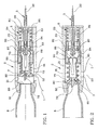
- Fig. 1 is a fragmentary longitudinal section view of a piercing apparatus to pierce a compressed gas bottle for quickly inflating a sack according to the present invention, in a loaded condition, before piercing the bottle;
- Fig. 2 is a fragmentary longitudinal section view of the piercing apparatus in Fig.1, in a condition after piercing the bottle;
- Fig. 3 is a longitudinal section view of a first embodiment of a reloading tool for reloading the apparatus in Fig. 1, after the operation of the release mechanism;
- Fig. 4 is a longitudinal section view of a second embodiment of a reloading tool for reloading the apparatus in Fig. 1, after the operation of the release mechanism;
- Figs. 5 and 6 are diagrammatic longitudinal section views showing the piercing apparatus before and after its release mechanism being reloaded, respectively;
- Fig. 7 is a diagrammatic, partially sectioned, front view of the piercing apparatus according to the invention in a wait condition, the apparatus being applied to a closed bag having a shoulder-strap depicted by a dotted line;
- Fig. 8 is a diagrammatic, partially sectioned, front view of the piercing apparatus in Fig. 7 in a operated state, with the bag being consequently opened;
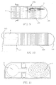
- Fig. 9 is a diagrammatic top view showing in a phantom view the piercing apparatus according to the invention in a wait condition, the piercing apparatus being applied to a rescue device;
- Fig. 10 is a diagrammatic fragmentary top view showing the rescue device in Fig. 9 in a operated state, the sack thereof being fully ejected; and
- Fig. 11 is a diagrammatic cross-section view taken along line A-A in Fig. 9.
-
- Referring to the drawing, a piercing apparatus according to the invention is shown as a whole in Figs. 1 and 2 in a wait condition and in an operated state, respectively.
- By way of example, such a piercing apparatus can be employed in a self-emptying
bag 100, which is depicted by dotted lines in a closed condition (Fig. 7) and in a following consequently opened condition (Fig. 8). By way of example, thebag 100 is endowed with a shoulder-strap 200. Thebag 100 is provided with afolding cover 101. Further, with respect to closure means of thefolding cover 101, that is diagrammatically shown in 300, it can be of any suitable kind, such as press-stud, Velcro (trade name) or the like, provided that it is yielding under the action of an ejection device, using the piercing apparatus according to the invention, in order to allow the bag to be opened and its contents to fall down. - Conveniently the
bag 100 is lined inside by alining 400 shaped as a pocket that is preferably held, although this is not shown in the drawing, in its upper hem by the edge of the bag in a removable way, e.g. by means of a zip or so called Velcro. Thus, by opening the zip or moving away the edges of Velcro from each other, a hand of a person may enter easily aspace 401 between the bottom of thelining 400 and thebase 102 of thebag 100. - The bottle piercing apparatus according to the invention is located in the
space 401. - The airtight
expandable sack 1, as diagrammatically depicted in its collapsed state in Fig. 7, is arranged in a collected way, e.g. folded, under thelining 400. In this inflated state (Fig. 8) the expandable sack l'takes on the form of a prismatic body, so to be able to keep thelining 400 overturned in 400' as shown in the same figures. - At the bottom the
expandable sack 1 is hermetically connected throughconnection duct 10 to anelongated housing 20 of a compressedgas feeder 2. Theelongated housing 20 can be made of a suitable plastic material. - The
compressed gas feeder 2 is located below theexpandable sack 1, being preferably arranged betweenrestraint panels 5 e.g. of a suitable foamy plastic material, in order to prevent the compressedgas 2 from wandering troublesomely on thebase 102 of the bag. - As shown in Fig.1, which is a longitudinal section view of the
compressed gas feeder 2, the generally cylindrical,elongated housing 20 thereof, whoseinner chamber 21 is in communication with theexpandable sack 1, frontally carries asmall bottle 6 of compressed air or other gas and, in a sequence from an end to the other end thereof, a spring-charged piercing element 7 and arelease mechanism 8. - The
small gas bottle 6, having a pierceable sealedmouth 60, is screwed to theelongated housing 20 by means of its externally threadedneck 61. The small gas bottle has such a capacity that theexpandable sack 1, after being inflated instantaneously, is able with its expansion to exert a sufficient force to expel objects contained inside thebag 100 between thelining 400 and thebag cover 101 upon the opening of the closure means and the overturning of the cover. - The
gas bottle 6 is closed in itsmouth 60 by a septum that is easily pierceable by the piercing element 7 provided with apiercing bit 72. Thepiercing bit 72, preferably as a mouthpiece of a flute, is shaped so that the cut portion of septum remains in part laterally attached to the septum, without obstructing the emission of gas. In addition, thepiercing bit 72 has anaxial passageway 73. - The
release mechanism 8, which pushes the piercing element 7 against thegas bottle 6, comprises a release member being connected to aflexible transmission 30 of control means 3, e.g. the control means of a self-emptying bag in Figs. 7 and 8. - According to the present invention, such a release member is a
protuberance 87, that is slidable in theinner chamber 21 of theelongated housing 20 by the operation of theflexible transmission 30 against a counteractingspring 89. Preferably, theprotuberance 87 is rigidly connected to acylindrical element 83 that is provided with at least a pair ofopposed tooth 84. Thesetooth 84 are designed to slide ongrooves 85 that are provided in theinner chamber 21 of theelongated housing 20. - The piercing element 7 is fixed to one end of a
collet chuck 70, which, at the other end, is provided withfingers 88 to grip theprotuberance 87 of therelease mechanism 8. Thecollet chuck 70 is very similar to that one of a propelling pencil and can be made of plastic material. - The
collet chuck 70, being movable between a gripping condition (Fig. 1) and a releasing condition of the protuberance 87 (Fig. 2), is slidable coaxially with respect to anexternal cam profile 90 surrounding at least thefingers 88 under the action of aspiral spring 91. Thespiral spring 91 is abutted between aflange 92 of the front end of thecollet chuck 70 and theexternal cam profile 90. Theexternal cam profile 90, that is in abutment against an internalcircumferential projection 93 of theinner chamber 21 of theelongated housing 20, has aninternal space 94, that is preferably cylindrical, with a consecutive frusto-conical portion 95. Then, such an internal space is adapted to receive and retain thefingers 88 of thecollet chuck 70 in engagement with theprotuberance 87 against the slide of thesame collet chuck 70. - In order to assemble the parts of the piercing apparatus inside the
inner chamber 21 of theelongated housing 20, a portion of the latter near the connection with thegas bottle 6 is screwed to the remaining portion of theelongated housing 20. - The operation of the piercing apparatus according to the invention is as follows.
- By manually acting on the control means 3, which is generally a Bowden cable, its
flexible transmission 30 being connected to theprotuberance 87, causes theprotuberance 87 to slide, by virtue of itstooth 84 engaging thegrooves 85 of theinner chamber 21 of theelongated housing 20 against the action of the counteractingspring 89. By thespring 89 theprotuberance 87 loses the engagement with thefingers 88 of thecollet chuck 70. The fingers, for example four in number, being retained no longer by theprotuberance 87 against the cylindrical-frustoconical space 94-95 of thecam profile 90, are able to pass through thecylindrical portion 94 of said space 94-95. Thecollet chuck 70, that is pushed by thespring 91 in abutment between theflange 92 of thesame collet chuck 70 and thecam profile 90, is obliged to travel suddenly toward the front end of theelongated housing 20, where thesmall gas bottle 6 is screwed. The piercing element 7, having apassageway 73 inside, pierces the sealedmouth 60 of the small bottle and causes the compressed gas therein contained to exit, to pass through thepassage 22 into theexpandable sack 1. Theexpandable sack 1 is inflated immediately. - In order to prevent the compressed gas from coming out through the rear portion of the
housing 20, aseal gasket 99, being situated around the connection with theflexible transmission 30 of the release element, is provided. - With reference to Figs. 3 to 6, which are diagrammatic section views, there is shown a tool for reloading the piercing apparatus according to the invention. In a first embodiment thereof, shown in Fig. 3, the reloading tool has an elongated cylindrical body, including a maximum diameter,
first section 50, an intermediate diameter,second section 51, and a minimum diameter,third section 52. The maximum diameter,first section 50 is internally hollow and is provided with an internal thread for screwing onto the threaded neck of thegas bottle 6. Thesecond section 51, that is externally threaded, has a diameter equal to that of the neck of thegas bottle 6 with same thread. Finally, the minimum diameter, internally hollow,third section 52 is such that it surrounds the piercing element 7. By screwing the tool in Fig. 3 as shown in Figs. 5 and 6, onto a bottle and then onto the mouth of theelongated housing 20, at the same way of a new bottle, thesection 52 of the tool causes thecollet chock 70 to move backward until thefingers 88 of thecollet chock 70 engage theprotuberance 87 of the release element. This engagement is made temporarily firm by thecam profile 90, against which thefingers 88 are retained, until the operation of the control means 3. - With reference to Fig. 4, a second embodiment of the tool for reloading the piercing apparatus according to the invention is shown. This second embodiment is characterized by a shaped
body 53 comprising an externally threadedsection 51 being equal to that one of the neck of the small bottle and ahollow end portion 52 such that it surrounds the piercing element 7 and cause it to move backward until the fingers of thecollet chock 70 engage theprotuberance 87 of the release element, as described with reference to the first embodiment of tool. In this second embodiment, the shapedbody 53 acts as a handle. - At this moment, the reloading tool can be screwed and instead of it a new charged
small bottle 6 can be located. - It is clear that the operation for restoring the
expandable sack 1 inside a bag and reloading the piercing device by a new small bottle can be easily performed by any owner of the same bag, thanks to the characteristics of the piercing apparatus of the invention and to the reloading tools. - However, the piercing apparatus of the invention can have other employment. For example, with reference to Figs. 9 to 11, a sea rescue device is diagrammatically shown. In a container 104 a
compressed gas feeder 2 is located side to side to a rolled upexpandable sack 1, as shown in Fig. 11. Thecontainer 104 has aslidable cover 105 with ahandle 106. A free end of control means is connected to theslidable cover 104. Thereby, when thecover 104 is pulled for uncovering thesack 1, thesack 1 is inflated in virtue of the piercing of thesmall bottle 6.
Claims (6)
- A piercing apparatus for piercing a small compressed gas bottle to quickly inflate a sack, comprising:characterized in that:an expandable sack (1) being arranged on a base (102; 103) of a container (100; 104);a compressed gas feeder (2) located below the expandable sack (1), including:a small compressed gas bottle (6) having a pierceable mouth (60) and an externally threaded neck (61),a housing (20) being connected to the small compressed gas bottle (6) and to the expandable sack (1), and in an inner chamber (21) of the housing a piercing element (7) having a bit (72) provided with an axial passageway (73) communicating with said expandable sack (1),a release mechanism (8), being charged by a counteracting spring (89) to push the piercing element (7) against the small compressed gas bottle (6), comprising a release element being connected to a flexible transmission (30) of control means (3);said release element is a protuberance (87) and is slidably mounted in said inner chamber (21) of the elongated housing (20) by the operation of the flexible transmission (30) against the counteracting spring (89); andsaid piercing element (7) is fixed on a front end of a collet chock (70), which, as such, is provided, in its rear end, with fingers (88) to grip said protuberance (87) of the release element; said collet chock (70) being slidable between a gripping condition and a releasing condition of said protuberance (87) upon the operation of control means.
- The piercing device according to claim 1, characterized in that said collet chuck (70) is slidable coaxially with respect to an external cam profile (90) surrounding at least said fingers (88) under the action of a spiral spring (91) being abutted between a flange (92) of said front end of the collet chuck (70) and said external cam profile (90); the external cam profile (90), which is in abutment against an internal circumferential projection (93) of said inner chamber (21) of the elongated housing (20), having an internal space adapted to receive and retain said fingers (88) of the collet chuck (70) in engagement with the protuberance (87) against the slide of the same collet chuck (70).
- The piercing device according to claim 1, characterized in that a portion of the elongated housing (20) near the connection with said gas bottle (6) is screwed to the remaining portion of the elongated housing (20).
- The piercing device according to claim 1, characterized in that a seal gasket is situated around the connection with said flexible transmission (30) of said release element.
- A tool for reloading the piercing apparatus according to claim 1, characterized in that this reloading tool has an elongated cylindrical body, including a maximum diameter, first section (50), which is internally hollow and is provided with an internal thread for screwing onto the threaded neck of a gas bottle (6), a second section (51), that is externally threaded, having a diameter equal to that of the neck of the gas bottle (6), and a minimum diameter, third section (52), being internally hollow such that it surrounds the piercing element (7) and causes the collet chock (70) to move backward until the fingers (88) of the collet chock (70) engage the protuberance (87) of the release element.
- A tool for reloading the piercing apparatus according to claim 1, characterized in that said tool has a shaped body (53) comprising an externally threaded section (51) being equal to that one of the neck of the small bottle and a hollow end portion (52) such that it surrounds the piercing element (7) and causes it to move backward until the fingers of the collet chock (70) engage the protuberance (87).
Applications Claiming Priority (2)
| Application Number | Priority Date | Filing Date | Title |
|---|---|---|---|
| ITRM20030473 | 2003-10-15 | ||
| IT000473A ITRM20030473A1 (en) | 2003-10-15 | 2003-10-15 | DRILLING DEVICE FOR A GAS BOTTLE |
Publications (2)
| Publication Number | Publication Date |
|---|---|
| EP1523902A1 true EP1523902A1 (en) | 2005-04-20 |
| EP1523902B1 EP1523902B1 (en) | 2006-12-13 |
Family
ID=30131615
Family Applications (1)
| Application Number | Title | Priority Date | Filing Date |
|---|---|---|---|
| EP04425766A Expired - Lifetime EP1523902B1 (en) | 2003-10-15 | 2004-10-12 | Piercing apparatus for piercing a small compressed gas bottle to quickly inflate a sack and tool for reloading the piercing apparatus |
Country Status (6)
| Country | Link |
|---|---|
| US (1) | US6991005B2 (en) |
| EP (1) | EP1523902B1 (en) |
| JP (1) | JP2005119748A (en) |
| AT (1) | ATE347826T1 (en) |
| DE (1) | DE602004003655D1 (en) |
| IT (1) | ITRM20030473A1 (en) |
Cited By (2)
| Publication number | Priority date | Publication date | Assignee | Title |
|---|---|---|---|---|
| CN104290128A (en) * | 2014-09-24 | 2015-01-21 | 福州大学 | Paper flowerpot punching machine driven by connection rods and use method of paper flowerpot punching machine |
| EP2926869A1 (en) * | 2013-12-13 | 2015-10-07 | Ortovox Sportartikel GmbH | Airbag system for protecting individuals |
Families Citing this family (10)
| Publication number | Priority date | Publication date | Assignee | Title |
|---|---|---|---|---|
| US7669616B2 (en) * | 2006-12-20 | 2010-03-02 | Ultra Electronics Ocean Systems, Inc. | Apparatus for puncturing a gas filled bottle |
| US20090246085A1 (en) * | 2008-03-31 | 2009-10-01 | Helicos Biosciences Corporation | Liquid Handling System and Methods for Mixing and Delivering Liquid Reagents |
| FR2976269B1 (en) * | 2011-06-08 | 2013-06-28 | Rexam Dispensing Sys | FLUID FOR DISPENSING A FLUID PRODUCT |
| WO2014018332A1 (en) * | 2012-07-23 | 2014-01-30 | Carleton Technologies, Inc. | Inflator assembly adapted for manual or automatic inflation |
| US9821183B2 (en) | 2014-07-11 | 2017-11-21 | Kidde Technologies, Inc. | Motorized actuator for a fire extinguisher |
| US9539452B2 (en) * | 2014-07-11 | 2017-01-10 | Kidde Technologies, Inc. | Rapid pressure diffusion actuator for a fire extinguisher |
| US9649520B2 (en) | 2014-07-11 | 2017-05-16 | Kidde Technologies, Inc. | Burst disc puncture pressure-imbalance actuator for a fire extinguisher |
| US9861846B2 (en) * | 2015-01-22 | 2018-01-09 | Kidde Technologies, Inc. | Spring-collet mechanism for activating a fire extinguisher |
| CN111322907B (en) * | 2020-03-05 | 2022-04-29 | 观典防务技术股份有限公司 | Power nitrogen gas bottle in pure mechanical structure mode for puncturing electric shock bomb |
| CN119175143B (en) * | 2024-11-22 | 2025-02-14 | 寿光市中瑞生物科技股份有限公司 | A sorbitol particle grinding machine |
Citations (3)
| Publication number | Priority date | Publication date | Assignee | Title |
|---|---|---|---|---|
| US5458164A (en) * | 1993-08-24 | 1995-10-17 | La Rue International Inc. | Luggage stuffer |
| EP0904710A1 (en) * | 1997-09-30 | 1999-03-31 | Benedetto Fedeli | A self-emptying bag |
| EP1110475A1 (en) * | 1999-12-16 | 2001-06-27 | Benedetto Fedeli | An ejection device to expel objects from the inside of a bag in the event of a bagsnatching |
Family Cites Families (2)
| Publication number | Priority date | Publication date | Assignee | Title |
|---|---|---|---|---|
| US5601124A (en) * | 1995-02-07 | 1997-02-11 | Halkey-Roberts Corporation | Autoinflator with apertured housing |
| US6705488B2 (en) * | 2001-09-07 | 2004-03-16 | Halkey-Roberts Corporation | Bobbin for automatic inflator |
-
2003
- 2003-10-15 IT IT000473A patent/ITRM20030473A1/en unknown
-
2004
- 2004-10-12 EP EP04425766A patent/EP1523902B1/en not_active Expired - Lifetime
- 2004-10-12 DE DE602004003655T patent/DE602004003655D1/en not_active Expired - Lifetime
- 2004-10-12 AT AT04425766T patent/ATE347826T1/en not_active IP Right Cessation
- 2004-10-13 US US10/962,543 patent/US6991005B2/en not_active Expired - Fee Related
- 2004-10-14 JP JP2004300296A patent/JP2005119748A/en active Pending
Patent Citations (3)
| Publication number | Priority date | Publication date | Assignee | Title |
|---|---|---|---|---|
| US5458164A (en) * | 1993-08-24 | 1995-10-17 | La Rue International Inc. | Luggage stuffer |
| EP0904710A1 (en) * | 1997-09-30 | 1999-03-31 | Benedetto Fedeli | A self-emptying bag |
| EP1110475A1 (en) * | 1999-12-16 | 2001-06-27 | Benedetto Fedeli | An ejection device to expel objects from the inside of a bag in the event of a bagsnatching |
Cited By (3)
| Publication number | Priority date | Publication date | Assignee | Title |
|---|---|---|---|---|
| EP2926869A1 (en) * | 2013-12-13 | 2015-10-07 | Ortovox Sportartikel GmbH | Airbag system for protecting individuals |
| CN104290128A (en) * | 2014-09-24 | 2015-01-21 | 福州大学 | Paper flowerpot punching machine driven by connection rods and use method of paper flowerpot punching machine |
| CN104290128B (en) * | 2014-09-24 | 2016-05-04 | 福州大学 | Paper flower basin puncher and using method thereof that a kind of connecting rod drives |
Also Published As
| Publication number | Publication date |
|---|---|
| ITRM20030473A1 (en) | 2005-04-16 |
| ATE347826T1 (en) | 2007-01-15 |
| US20050081947A1 (en) | 2005-04-21 |
| JP2005119748A (en) | 2005-05-12 |
| EP1523902B1 (en) | 2006-12-13 |
| US6991005B2 (en) | 2006-01-31 |
| ITRM20030473A0 (en) | 2003-10-15 |
| DE602004003655D1 (en) | 2007-01-25 |
Similar Documents
| Publication | Publication Date | Title |
|---|---|---|
| EP1523902B1 (en) | Piercing apparatus for piercing a small compressed gas bottle to quickly inflate a sack and tool for reloading the piercing apparatus | |
| US5301631A (en) | Balloon emergency locating device | |
| US4562837A (en) | Air escape filter apparatus | |
| US8469015B2 (en) | Low cost rescue launcher system | |
| EP0119333B1 (en) | Vacuum packaged inflatable flotation device | |
| US4498604A (en) | Automatic inflator | |
| US5884362A (en) | Expandable handle of luggage | |
| CN105121996B (en) | Delivery and the apparatus and method fetched for grenade | |
| US3437245A (en) | Powder dispenser | |
| EP1110475B1 (en) | An ejection device to expel objects from the inside of a bag in the event of a bagsnatching | |
| EP0182214B1 (en) | Parachute system and aircraft ejection seat incorporating the same | |
| US6373384B1 (en) | Inflatable security device | |
| US6168046B1 (en) | Vitamin and pill dispensing device | |
| US5813581A (en) | Pouch for truncheon | |
| US20040123793A1 (en) | Man overboard locator device | |
| US4803745A (en) | Survival knife sheath | |
| US4805533A (en) | Swimmer pyrotechnic signal device | |
| US7300206B2 (en) | Self-emptying bag having a quick coupling buckle assembly, in particular for shoulder-strap | |
| US6651934B2 (en) | Rescue system for rescuing persons by air | |
| JP2008029370A (en) | Cracker shooting device | |
| US3289827A (en) | Container for use in space ships | |
| US20230068361A1 (en) | Shock tube coil system | |
| JPH0631355Y2 (en) | Push cracker | |
| JPH0631351Y2 (en) | Tubular cracker | |
| FR3073499A1 (en) | EMERGENCY PARACHUTE EJECTOR FOR PARAGLIDING OR AIRCRAFT ULTRALEGER |
Legal Events
| Date | Code | Title | Description |
|---|---|---|---|
| PUAI | Public reference made under article 153(3) epc to a published international application that has entered the european phase |
Free format text: ORIGINAL CODE: 0009012 |
|
| AK | Designated contracting states |
Kind code of ref document: A1 Designated state(s): AT BE BG CH CY CZ DE DK EE ES FI FR GB GR HU IE IT LI LU MC NL PL PT RO SE SI SK TR |
|
| AX | Request for extension of the european patent |
Extension state: AL HR LT LV MK |
|
| 17P | Request for examination filed |
Effective date: 20051017 |
|
| AKX | Designation fees paid |
Designated state(s): AT BE BG CH CY CZ DE DK EE ES FI FR GB GR HU IE IT LI LU MC NL PL PT RO SE SI SK TR |
|
| GRAP | Despatch of communication of intention to grant a patent |
Free format text: ORIGINAL CODE: EPIDOSNIGR1 |
|
| GRAS | Grant fee paid |
Free format text: ORIGINAL CODE: EPIDOSNIGR3 |
|
| GRAA | (expected) grant |
Free format text: ORIGINAL CODE: 0009210 |
|
| AK | Designated contracting states |
Kind code of ref document: B1 Designated state(s): AT BE BG CH CY CZ DE DK EE ES FI FR GB GR HU IE IT LI LU MC NL PL PT RO SE SI SK TR |
|
| PG25 | Lapsed in a contracting state [announced via postgrant information from national office to epo] |
Ref country code: IT Free format text: LAPSE BECAUSE OF FAILURE TO SUBMIT A TRANSLATION OF THE DESCRIPTION OR TO PAY THE FEE WITHIN THE PRESCRIBED TIME-LIMIT;WARNING: LAPSES OF ITALIAN PATENTS WITH EFFECTIVE DATE BEFORE 2007 MAY HAVE OCCURRED AT ANY TIME BEFORE 2007. THE CORRECT EFFECTIVE DATE MAY BE DIFFERENT FROM THE ONE RECORDED. Effective date: 20061213 Ref country code: NL Free format text: LAPSE BECAUSE OF FAILURE TO SUBMIT A TRANSLATION OF THE DESCRIPTION OR TO PAY THE FEE WITHIN THE PRESCRIBED TIME-LIMIT Effective date: 20061213 Ref country code: SI Free format text: LAPSE BECAUSE OF FAILURE TO SUBMIT A TRANSLATION OF THE DESCRIPTION OR TO PAY THE FEE WITHIN THE PRESCRIBED TIME-LIMIT Effective date: 20061213 Ref country code: FI Free format text: LAPSE BECAUSE OF FAILURE TO SUBMIT A TRANSLATION OF THE DESCRIPTION OR TO PAY THE FEE WITHIN THE PRESCRIBED TIME-LIMIT Effective date: 20061213 Ref country code: RO Free format text: LAPSE BECAUSE OF FAILURE TO SUBMIT A TRANSLATION OF THE DESCRIPTION OR TO PAY THE FEE WITHIN THE PRESCRIBED TIME-LIMIT Effective date: 20061213 Ref country code: LI Free format text: LAPSE BECAUSE OF FAILURE TO SUBMIT A TRANSLATION OF THE DESCRIPTION OR TO PAY THE FEE WITHIN THE PRESCRIBED TIME-LIMIT Effective date: 20061213 Ref country code: CH Free format text: LAPSE BECAUSE OF FAILURE TO SUBMIT A TRANSLATION OF THE DESCRIPTION OR TO PAY THE FEE WITHIN THE PRESCRIBED TIME-LIMIT Effective date: 20061213 Ref country code: BE Free format text: LAPSE BECAUSE OF FAILURE TO SUBMIT A TRANSLATION OF THE DESCRIPTION OR TO PAY THE FEE WITHIN THE PRESCRIBED TIME-LIMIT Effective date: 20061213 Ref country code: AT Free format text: LAPSE BECAUSE OF FAILURE TO SUBMIT A TRANSLATION OF THE DESCRIPTION OR TO PAY THE FEE WITHIN THE PRESCRIBED TIME-LIMIT Effective date: 20061213 Ref country code: DK Free format text: LAPSE BECAUSE OF FAILURE TO SUBMIT A TRANSLATION OF THE DESCRIPTION OR TO PAY THE FEE WITHIN THE PRESCRIBED TIME-LIMIT Effective date: 20061213 Ref country code: PL Free format text: LAPSE BECAUSE OF FAILURE TO SUBMIT A TRANSLATION OF THE DESCRIPTION OR TO PAY THE FEE WITHIN THE PRESCRIBED TIME-LIMIT Effective date: 20061213 Ref country code: SK Free format text: LAPSE BECAUSE OF FAILURE TO SUBMIT A TRANSLATION OF THE DESCRIPTION OR TO PAY THE FEE WITHIN THE PRESCRIBED TIME-LIMIT Effective date: 20061213 Ref country code: CZ Free format text: LAPSE BECAUSE OF FAILURE TO SUBMIT A TRANSLATION OF THE DESCRIPTION OR TO PAY THE FEE WITHIN THE PRESCRIBED TIME-LIMIT Effective date: 20061213 |
|
| REG | Reference to a national code |
Ref country code: GB Ref legal event code: FG4D |
|
| REG | Reference to a national code |
Ref country code: CH Ref legal event code: EP |
|
| REG | Reference to a national code |
Ref country code: IE Ref legal event code: FG4D |
|
| REF | Corresponds to: |
Ref document number: 602004003655 Country of ref document: DE Date of ref document: 20070125 Kind code of ref document: P |
|
| PG25 | Lapsed in a contracting state [announced via postgrant information from national office to epo] |
Ref country code: BG Free format text: LAPSE BECAUSE OF FAILURE TO SUBMIT A TRANSLATION OF THE DESCRIPTION OR TO PAY THE FEE WITHIN THE PRESCRIBED TIME-LIMIT Effective date: 20070313 Ref country code: SE Free format text: LAPSE BECAUSE OF FAILURE TO SUBMIT A TRANSLATION OF THE DESCRIPTION OR TO PAY THE FEE WITHIN THE PRESCRIBED TIME-LIMIT Effective date: 20070313 |
|
| PG25 | Lapsed in a contracting state [announced via postgrant information from national office to epo] |
Ref country code: DE Free format text: LAPSE BECAUSE OF FAILURE TO SUBMIT A TRANSLATION OF THE DESCRIPTION OR TO PAY THE FEE WITHIN THE PRESCRIBED TIME-LIMIT Effective date: 20070314 |
|
| PG25 | Lapsed in a contracting state [announced via postgrant information from national office to epo] |
Ref country code: ES Free format text: LAPSE BECAUSE OF FAILURE TO SUBMIT A TRANSLATION OF THE DESCRIPTION OR TO PAY THE FEE WITHIN THE PRESCRIBED TIME-LIMIT Effective date: 20070324 |
|
| PG25 | Lapsed in a contracting state [announced via postgrant information from national office to epo] |
Ref country code: PT Free format text: LAPSE BECAUSE OF FAILURE TO SUBMIT A TRANSLATION OF THE DESCRIPTION OR TO PAY THE FEE WITHIN THE PRESCRIBED TIME-LIMIT Effective date: 20070514 |
|
| NLV1 | Nl: lapsed or annulled due to failure to fulfill the requirements of art. 29p and 29m of the patents act | ||
| REG | Reference to a national code |
Ref country code: CH Ref legal event code: PL |
|
| EN | Fr: translation not filed | ||
| PLBE | No opposition filed within time limit |
Free format text: ORIGINAL CODE: 0009261 |
|
| STAA | Information on the status of an ep patent application or granted ep patent |
Free format text: STATUS: NO OPPOSITION FILED WITHIN TIME LIMIT |
|
| 26N | No opposition filed |
Effective date: 20070914 |
|
| PG25 | Lapsed in a contracting state [announced via postgrant information from national office to epo] |
Ref country code: GR Free format text: LAPSE BECAUSE OF FAILURE TO SUBMIT A TRANSLATION OF THE DESCRIPTION OR TO PAY THE FEE WITHIN THE PRESCRIBED TIME-LIMIT Effective date: 20070314 Ref country code: FR Free format text: LAPSE BECAUSE OF FAILURE TO SUBMIT A TRANSLATION OF THE DESCRIPTION OR TO PAY THE FEE WITHIN THE PRESCRIBED TIME-LIMIT Effective date: 20070803 |
|
| PG25 | Lapsed in a contracting state [announced via postgrant information from national office to epo] |
Ref country code: MC Free format text: LAPSE BECAUSE OF NON-PAYMENT OF DUE FEES Effective date: 20071031 |
|
| PG25 | Lapsed in a contracting state [announced via postgrant information from national office to epo] |
Ref country code: IE Free format text: LAPSE BECAUSE OF NON-PAYMENT OF DUE FEES Effective date: 20071012 |
|
| PG25 | Lapsed in a contracting state [announced via postgrant information from national office to epo] |
Ref country code: FR Free format text: LAPSE BECAUSE OF FAILURE TO SUBMIT A TRANSLATION OF THE DESCRIPTION OR TO PAY THE FEE WITHIN THE PRESCRIBED TIME-LIMIT Effective date: 20061213 |
|
| PG25 | Lapsed in a contracting state [announced via postgrant information from national office to epo] |
Ref country code: EE Free format text: LAPSE BECAUSE OF FAILURE TO SUBMIT A TRANSLATION OF THE DESCRIPTION OR TO PAY THE FEE WITHIN THE PRESCRIBED TIME-LIMIT Effective date: 20061213 |
|
| GBPC | Gb: european patent ceased through non-payment of renewal fee |
Effective date: 20081012 |
|
| PG25 | Lapsed in a contracting state [announced via postgrant information from national office to epo] |
Ref country code: LU Free format text: LAPSE BECAUSE OF NON-PAYMENT OF DUE FEES Effective date: 20071012 Ref country code: CY Free format text: LAPSE BECAUSE OF FAILURE TO SUBMIT A TRANSLATION OF THE DESCRIPTION OR TO PAY THE FEE WITHIN THE PRESCRIBED TIME-LIMIT Effective date: 20061213 |
|
| PG25 | Lapsed in a contracting state [announced via postgrant information from national office to epo] |
Ref country code: TR Free format text: LAPSE BECAUSE OF FAILURE TO SUBMIT A TRANSLATION OF THE DESCRIPTION OR TO PAY THE FEE WITHIN THE PRESCRIBED TIME-LIMIT Effective date: 20061213 Ref country code: HU Free format text: LAPSE BECAUSE OF FAILURE TO SUBMIT A TRANSLATION OF THE DESCRIPTION OR TO PAY THE FEE WITHIN THE PRESCRIBED TIME-LIMIT Effective date: 20070614 |
|
| PG25 | Lapsed in a contracting state [announced via postgrant information from national office to epo] |
Ref country code: GB Free format text: LAPSE BECAUSE OF NON-PAYMENT OF DUE FEES Effective date: 20081012 |