EP1523874A1 - Messeinrichtung zur Messung von Inhaltsstoffen in Erntegut - Google Patents
Messeinrichtung zur Messung von Inhaltsstoffen in Erntegut Download PDFInfo
- Publication number
- EP1523874A1 EP1523874A1 EP04104899A EP04104899A EP1523874A1 EP 1523874 A1 EP1523874 A1 EP 1523874A1 EP 04104899 A EP04104899 A EP 04104899A EP 04104899 A EP04104899 A EP 04104899A EP 1523874 A1 EP1523874 A1 EP 1523874A1
- Authority
- EP
- European Patent Office
- Prior art keywords
- measuring device
- vehicle
- measuring
- crop
- mounting
- Prior art date
- Legal status (The legal status is an assumption and is not a legal conclusion. Google has not performed a legal analysis and makes no representation as to the accuracy of the status listed.)
- Granted
Links
- 239000000463 material Substances 0.000 claims abstract description 16
- 239000000470 constituent Substances 0.000 claims abstract 2
- 230000003287 optical effect Effects 0.000 claims description 3
- 238000011156 evaluation Methods 0.000 claims description 2
- 238000003306 harvesting Methods 0.000 description 8
- 239000004615 ingredient Substances 0.000 description 7
- 238000005259 measurement Methods 0.000 description 5
- 230000005540 biological transmission Effects 0.000 description 3
- 240000008042 Zea mays Species 0.000 description 2
- 235000002017 Zea mays subsp mays Nutrition 0.000 description 2
- 239000000835 fiber Substances 0.000 description 2
- 239000004459 forage Substances 0.000 description 2
- 239000000126 substance Substances 0.000 description 2
- XLYOFNOQVPJJNP-UHFFFAOYSA-N water Substances O XLYOFNOQVPJJNP-UHFFFAOYSA-N 0.000 description 2
- 244000025254 Cannabis sativa Species 0.000 description 1
- 235000019750 Crude protein Nutrition 0.000 description 1
- 241001124569 Lycaenidae Species 0.000 description 1
- -1 Rohprotein- Substances 0.000 description 1
- 229920002472 Starch Polymers 0.000 description 1
- 235000005824 Zea mays ssp. parviglumis Nutrition 0.000 description 1
- 235000016383 Zea mays subsp huehuetenangensis Nutrition 0.000 description 1
- 235000013339 cereals Nutrition 0.000 description 1
- 230000006835 compression Effects 0.000 description 1
- 238000007906 compression Methods 0.000 description 1
- 238000010276 construction Methods 0.000 description 1
- 235000005822 corn Nutrition 0.000 description 1
- 230000001419 dependent effect Effects 0.000 description 1
- 238000003745 diagnosis Methods 0.000 description 1
- 210000003608 fece Anatomy 0.000 description 1
- 235000013305 food Nutrition 0.000 description 1
- 229910052500 inorganic mineral Inorganic materials 0.000 description 1
- 239000007788 liquid Substances 0.000 description 1
- 239000010871 livestock manure Substances 0.000 description 1
- 235000009973 maize Nutrition 0.000 description 1
- 239000011707 mineral Substances 0.000 description 1
- 239000011368 organic material Substances 0.000 description 1
- 238000002310 reflectometry Methods 0.000 description 1
- 238000005070 sampling Methods 0.000 description 1
- 235000019698 starch Nutrition 0.000 description 1
- 239000008107 starch Substances 0.000 description 1
Images

Classifications
-
- G—PHYSICS
- G01—MEASURING; TESTING
- G01N—INVESTIGATING OR ANALYSING MATERIALS BY DETERMINING THEIR CHEMICAL OR PHYSICAL PROPERTIES
- G01N21/00—Investigating or analysing materials by the use of optical means, i.e. using sub-millimetre waves, infrared, visible or ultraviolet light
- G01N21/17—Systems in which incident light is modified in accordance with the properties of the material investigated
- G01N21/25—Colour; Spectral properties, i.e. comparison of effect of material on the light at two or more different wavelengths or wavelength bands
- G01N21/31—Investigating relative effect of material at wavelengths characteristic of specific elements or molecules, e.g. atomic absorption spectrometry
- G01N21/35—Investigating relative effect of material at wavelengths characteristic of specific elements or molecules, e.g. atomic absorption spectrometry using infrared light
- G01N21/3563—Investigating relative effect of material at wavelengths characteristic of specific elements or molecules, e.g. atomic absorption spectrometry using infrared light for analysing solids; Preparation of samples therefor
-
- A—HUMAN NECESSITIES
- A01—AGRICULTURE; FORESTRY; ANIMAL HUSBANDRY; HUNTING; TRAPPING; FISHING
- A01D—HARVESTING; MOWING
- A01D41/00—Combines, i.e. harvesters or mowers combined with threshing devices
- A01D41/12—Details of combines
- A01D41/127—Control or measuring arrangements specially adapted for combines
- A01D41/1277—Control or measuring arrangements specially adapted for combines for measuring grain quality
-
- A—HUMAN NECESSITIES
- A01—AGRICULTURE; FORESTRY; ANIMAL HUSBANDRY; HUNTING; TRAPPING; FISHING
- A01D—HARVESTING; MOWING
- A01D43/00—Mowers combined with apparatus performing additional operations while mowing
- A01D43/08—Mowers combined with apparatus performing additional operations while mowing with means for cutting up the mown crop, e.g. forage harvesters
- A01D43/085—Control or measuring arrangements specially adapted therefor
-
- G—PHYSICS
- G01—MEASURING; TESTING
- G01N—INVESTIGATING OR ANALYSING MATERIALS BY DETERMINING THEIR CHEMICAL OR PHYSICAL PROPERTIES
- G01N21/00—Investigating or analysing materials by the use of optical means, i.e. using sub-millimetre waves, infrared, visible or ultraviolet light
- G01N21/17—Systems in which incident light is modified in accordance with the properties of the material investigated
- G01N21/25—Colour; Spectral properties, i.e. comparison of effect of material on the light at two or more different wavelengths or wavelength bands
- G01N21/31—Investigating relative effect of material at wavelengths characteristic of specific elements or molecules, e.g. atomic absorption spectrometry
- G01N21/35—Investigating relative effect of material at wavelengths characteristic of specific elements or molecules, e.g. atomic absorption spectrometry using infrared light
- G01N21/359—Investigating relative effect of material at wavelengths characteristic of specific elements or molecules, e.g. atomic absorption spectrometry using infrared light using near infrared light
-
- G—PHYSICS
- G01—MEASURING; TESTING
- G01N—INVESTIGATING OR ANALYSING MATERIALS BY DETERMINING THEIR CHEMICAL OR PHYSICAL PROPERTIES
- G01N21/00—Investigating or analysing materials by the use of optical means, i.e. using sub-millimetre waves, infrared, visible or ultraviolet light
- G01N21/84—Systems specially adapted for particular applications
- G01N21/85—Investigating moving fluids or granular solids
-
- G—PHYSICS
- G01—MEASURING; TESTING
- G01N—INVESTIGATING OR ANALYSING MATERIALS BY DETERMINING THEIR CHEMICAL OR PHYSICAL PROPERTIES
- G01N21/00—Investigating or analysing materials by the use of optical means, i.e. using sub-millimetre waves, infrared, visible or ultraviolet light
- G01N21/84—Systems specially adapted for particular applications
- G01N2021/8466—Investigation of vegetal material, e.g. leaves, plants, fruits
Definitions
- the invention relates to a measuring device which is set up is to interact with a material to be examined and to capture at least one ingredient of the material, and the by means of a mounting device on a vehicle is fastened, so that the measuring device in the in the Holder device mounted state is operable from the vehicle processed and / or processed material to analyze.
- EP 1 053 671 A a measuring device is proposed, which is attached to an agricultural machine.
- the Crop material flows past the measuring device and is through the Measuring device with regard to certain properties examined, such as moisture content or content organic ingredients. It is proposed the measuring device inside the machine or on a sled outside the machine.
- the described sensor is used exclusively on the harvester.
- Suitable for analyzing ingredients of organic material Measuring devices usually comprise in the wavelength range Near-infrared (NIR) sensors working with Light sources and optical analyzers are equipped. Such sensors are relatively complicated and expensive. at Applications in which organic substances in both the Harvest as well as stationary to be analyzed proves the purchase of two sensors as required.
- NIR Near-infrared
- the measuring device of the mounting device detachable from the vehicle and separated from the vehicle suitable to design.
- the measuring device on the one hand on the vehicle be used, promoted by the latter On the other hand, it can also be analyzed by Vehicle and other for stationary analysis Materials are used.
- the same measuring device can thus on any type of vehicle (eg harvester, woodworking vehicle, self-propelled, attached or towed Harvesters such as combine harvester, forage harvester or baler, Feed mixer, seed drill, liquid manure distribution system) as well stationary (eg in the office, on a wagon scale, on a Acceptance of cereals or in elevator systems or for the analysis of daily feed rations) or in a car or truck mobile control of qualities are used.
- An advantage lies in the fact that the measuring device within a (in particular agricultural) enterprise widely can be used. This extends the operating time the measuring device from a few harvest weeks to the entire Year.
- a material analysis can, for example, with an optical Sensor be performed.
- Such sensors work in the Usually in the near infrared range.
- the measuring device can in Transmission and / or reflection mode and / or in one work any other wavelength range.
- the measuring device On the vehicle, the measuring device is in a mounting device attached, which makes it possible to examine the To bring material into an area where it is from the Measuring device is examined; it is thus a device available for sample presentation. Im separated from the vehicle Condition could be the measuring device without additional mounting device used and for example by hand in one Position in which they are to be examined with the Material cooperates. But there is also a (second) Mounting device for the measuring device use, so is These also expediently with a device for Sample presentation equipped. The sample may be at the Measurement are in a dormant or a moving state.
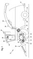
- the illustrated embodiment of the invention is at a Harvesting machine 10 ( Figures 1 and 2) and at a stationary Measuring container ( Figure 3) used.
- the one shown in Figure 1 Harvesting machine 10 in the manner of a self-propelled forage harvester builds on a frame 12, the front and rear wheels 14 and 16 is worn.
- the operation of the Harvesting machine 10 takes place from a driver's cab 18, of which From a Erntegutancevorides 20 is visible.
- the Erntegutabilityvoriques 20 in the illustrated Embodiment is a maize header, gut picked up, z.
- As corn, grass or the like is a chopper drum 22nd which chops it into small pieces and makes it one Releases conveyor 24.
- a first flow rate sensor 30 measures the distance between two pre-press rollers 32 located between the crop pick-up device 20 and the cutterhead 22 is arranged are, and between which the crop is conveyed through, by means of one of the spring-loaded pre-press roller 32nd operated sliding or rotary resistance (potentiometer). Farther the speed of one of the pre-compression rollers 32 by a second sensor 34 measured.
- sensors can Drive torque of the conveyor 24 and the post-shredder 28 measure.
- An on-board computer 40 connected to a display device 38 serves to record and evaluate the measured data.
- the Driving speed can be calculated from the data of Propulsion devices of the harvester 10 removed or over a radar sensor 48 are detected.
- a GPS (Global Positioning System) Sensor 42 for detecting the current Position can the yield by means of the on-board computer 40th be mapped to the specific area.
- a measuring device 46 for measurement certain ingredients of the crop provided. she decides the percentage of these ingredients in the crop and works optically in reflection mode in the visible range and / or near infrared range. On board computer 40 can do so Water, Rohprotein-, fat etc. of the crop georeferenced stored and by the display device 38 will be displayed.
- the measuring device 46 is also set up to record further parameters of the crop, namely the fiber length, the fiber content and the content Dry matter.
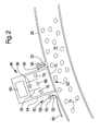
- the attachment of the measuring device 46 to the discharge chute 26 is shown in more detail in FIG.
- the flange 52 is bolted to the wall, welded or otherwise attached to it attached.
- the measuring device 46 has a cylindrical Housing 54, which extends into the interior of the flange 52nd extends.
- On the outside of the housing 54 is another, provided with the housing 54 fixedly connected flange 56, the on the flange connected to the wall of the discharge tray 26 52 rests.
- a threaded connection 58 supports the flange 56 of the housing 54 on the flange 52 of the wall.
- a Screw 58 could be any other, as possible fast and easy detachable and attachable connection selected become.
- the Electronics unit 60 is a separable electrical Plug connection 62 with the bus system 64 of the harvesting machine 10 connected to which the on-board computer 40 is connected.
- the bus system usually works according to a standard, such as CAN ISO 11783.
- the measuring device 46 contacts the Display device 38 with a separate page or alternatively only with values displayed on another page.
- a Light source 66 which by means of a collimator 68 light after down radiates.
- the light passes through a translucent Washer 70 at the bottom of the housing 54 and in the Delivery channel 72 in the discharge chute 26, through the crop 74th is encouraged.
- Detectors 76 passing through an opaque tube 78 of FIG the light source 66 are shielded.
- the detectors 76 are in the location, wavelength-specific, the reflectivity of the crop 74 are thus constructed as a spectrometer. To can in a conventional manner filters, grids or dispersive Elements are used.
- the detectors 76th From the of the detectors 76th provided measurements calculated by the electronic unit 60th the content of the crop 74 of certain ingredients, such as Water, starch, enzyme-soluble organic substances, non-organic minerals, crude protein, oil and the like.
- the measured values are sent via the bus system 64 to the on-board computer 40, which maps them location-dependent, and to the Display device 38, on which they are displayed can.
- the measuring device 46 shown in FIGS. 1 and 2 can, as shown in Figure 3, also on any other Place to be used. In Figure 3, it is at a stationary or portable container 82, which is a Sampling vessel acts.
- the cylindrical container 82 is on its side wall provided with a mounting device 84, where the measuring device 46 is attached.
- the Holder device 84 corresponds in its construction of the Mounting device 80 of Figure 2.
- the measuring device 46 is via the connector and a cable 86 (and usually a suitable interface) connected to a computer 88, the also connected to a keyboard 90 and a monitor 92 is.
- the measuring device 46 be used during harvest time on the harvester 10 can vary the content of the crop 74 at different To detect ingredients.
- the technically complex and expensive Measuring device 46 can when not in use, z. B. at night, easily be removed from the harvester 10, even before them Weather conditions protected in a safe place accommodate. It can also be attached to the container 82 become. In the container filled samples, for example consisting of crops of any kind, can by the same Measuring device 46 are examined. The measurement result is on displayed on the monitor 92 and in the computer 88 on a Storage medium stored. It would also be conceivable that Measuring device 46 itself with an input and To provide display device to them as a single device independent of other devices. The input and Display device can be removed and attached to the connector 62 connectable. About them is then the Power supply via mains, batteries or rechargeable battery.
- the signals output by the detectors 76 may be in some Be evaluated differently depending on at which mounting device the measuring device 46 is used. In other words, calibration values depend on Measuring device 46 from its attachment. To get out of it Avoid errors that occur without manual entries to make the electronics unit 60 of the Measuring device 46 in a preferred embodiment of Invention information about the mounting device 80th or 84, at which the measuring device 46 is located in each case, fed. This information can consist of data that is about the bus system 64 and the cable 86 are sent. For others Embodiments will provide this information through elements attached to the Flanges 52 transmitted by sensors of the measuring device 46 are detected, for example, optically, mechanically or magnetic. The measuring device 46 could alternatively be based on the recognize other connected to the bus system 64 participants, whether she is on the harvester 10 or in the Single operation ( Figure 3) is used.
- the bus system 64 allows also a diagnosis of the measuring device 46.
- the form of the data which the measuring device 46 depends on whether they are on the harvester 10 or is used stationary. So can different protocols used for data transmission or other data formats.
- the information in which form the data is transmitted therefore depends, as appropriate, in the manner described above from the information about the holding device 80 or 84, at which the measuring device 46 is located in each case from.
Landscapes
- Physics & Mathematics (AREA)
- Life Sciences & Earth Sciences (AREA)
- Spectroscopy & Molecular Physics (AREA)
- General Health & Medical Sciences (AREA)
- Analytical Chemistry (AREA)
- Biochemistry (AREA)
- Chemical & Material Sciences (AREA)
- General Physics & Mathematics (AREA)
- Immunology (AREA)
- Pathology (AREA)
- Health & Medical Sciences (AREA)
- Environmental Sciences (AREA)
- Investigating Or Analysing Materials By Optical Means (AREA)
- Combines (AREA)
- Management, Administration, Business Operations System, And Electronic Commerce (AREA)
Abstract
Description
- Fig. 1
- eine Erntemaschine mit einer Messeinrichtung in Seitenansicht und in schematischer Darstellung,
- Fig. 2
- eine vergrößerte Schnittansicht der an der Erntemaschine befestigten Messeinrichtung, und
- Fig. 3
- die Messeinrichtung mit einer zweiten Halterungseinrichtung und einem Computer zur Auswertung der Messergebnisse.
Claims (8)
- Messeinrichtung (46), die eingerichtet ist, mit einem zu untersuchenden Material zusammenzuwirken und wenigstens einen Inhaltsstoff des Materials zu erfassen, und die mittels einer Halterungseinrichtung (80) an einem Fahrzeug befestigbar ist, sodass die Messeinrichtung (46) in dem in der Halterungseinrichtung (80) befestigten Zustand betreibbar ist, von dem Fahrzeug be- und/oder verarbeitetes Material zu analysieren, dadurch gekennzeichnet, dass die Messeinrichtung (46) von der Halterungseinrichtung (80) trennbar und verwendbar ist, in einem stationären Einsatz Material zu untersuchen.
- Messeinrichtung (46) nach Anspruch 1, dadurch gekennzeichnet, dass sie einen optischen Sensor umfasst, der vorzugsweise im Nahinfrarotbereich arbeitet.
- Messeinrichtung (46) nach Anspruch 1 oder 2, dadurch gekennzeichnet, dass die Halterungseinrichtung (80) des Fahrzeugs und/oder eine zweite, vom Fahrzeug getrennte Halterungseinrichtung (84) mit einer Vorrichtung zur Probenpräsentation für die Messeinrichtung (46) versehen ist bzw. sind.
- Messeinrichtung (46) nach einem der Ansprüche 1 bis 3, dadurch gekennzeichnet, dass die Messeinrichtung (46) mit einem Bussystem (64) des Fahrzeugs verbindbar ist.
- Messeinrichtung (46) nach Anspruch 4, dadurch gekennzeichnet, dass die Messeinrichtung (46) über eine lösbare Steckverbindung (62) mit dem Bussystem (64) des Fahrzeugs verbindbar ist.
- Messeinrichtung (46) nach einem der vorhergehenden Ansprüche, dadurch gekennzeichnet, dass sie mit einer Anzeigeeinrichtung (38) des Fahrzeugs verbindbar ist, auf der ihre Messwerte anzeigbar sind.
- Messeinrichtung (46) nach einem der vorhergehenden Ansprüche, dadurch gekennzeichnet, dass der Messeinrichtung (46) eine Information über die Art der Halterungseinrichtung (80, 84), an der sie befestigt ist, zugeführt wird.
- Messeinrichtung (46) nach Anspruch 7, dadurch gekennzeichnet, dass die Messeinrichtung (46) die Information über die Art der Halterungseinrichtung (80, 84), an der sie befestigt ist, bei der Auswertung der Messwerte und/oder bei der Abgabe von Messdaten berücksichtigt.
Applications Claiming Priority (2)
| Application Number | Priority Date | Filing Date | Title |
|---|---|---|---|
| DE10348040A DE10348040A1 (de) | 2003-10-15 | 2003-10-15 | Messeinrichtung |
| DE10348040 | 2003-10-15 |
Publications (2)
| Publication Number | Publication Date |
|---|---|
| EP1523874A1 true EP1523874A1 (de) | 2005-04-20 |
| EP1523874B1 EP1523874B1 (de) | 2006-12-27 |
Family
ID=34353426
Family Applications (1)
| Application Number | Title | Priority Date | Filing Date |
|---|---|---|---|
| EP04104899A Expired - Lifetime EP1523874B1 (de) | 2003-10-15 | 2004-10-06 | Messeinrichtung zur Messung von Inhaltsstoffen in Erntegut |
Country Status (4)
| Country | Link |
|---|---|
| US (1) | US7169040B2 (de) |
| EP (1) | EP1523874B1 (de) |
| CA (1) | CA2483677C (de) |
| DE (2) | DE10348040A1 (de) |
Cited By (6)
| Publication number | Priority date | Publication date | Assignee | Title |
|---|---|---|---|---|
| EP1989936A1 (de) * | 2007-05-11 | 2008-11-12 | CLAAS Selbstfahrende Erntemaschinen GmbH | Messeinrichtung zur Inhaltsstofferfassung von landwirtschaftlichem Erntegut |
| EP2564685A1 (de) * | 2011-09-02 | 2013-03-06 | CLAAS Selbstfahrende Erntemaschinen GmbH | Landwirtschaftliche Erntemaschine |
| CN107079662A (zh) * | 2012-09-27 | 2017-08-22 | 株式会社久保田 | 联合收割机 |
| IT201800005823A1 (it) * | 2018-05-29 | 2019-11-29 | Apparecchiatura per l’analisi in tempo reale ed in linea del raccolto agricolo. | |
| EP3489632B1 (de) * | 2017-11-22 | 2021-07-14 | CLAAS Selbstfahrende Erntemaschinen GmbH | Messvorrichtung zur bestimmung eines aus schüttgut bestehenden massenstroms |
| DE102023126147A1 (de) | 2023-09-26 | 2025-03-27 | Deere & Company | Sensorzusammenbau, landwirtschaftliche Maschine und zugehöriges Verfahren |
Families Citing this family (37)
| Publication number | Priority date | Publication date | Assignee | Title |
|---|---|---|---|---|
| DE102004010772A1 (de) | 2004-03-05 | 2005-10-06 | Deere & Company, Moline | Austrageinrichtung mit einer Messeinrichtung |
| DE102005017121A1 (de) * | 2005-04-14 | 2006-10-19 | Deere & Company, Moline | Auswurfkrümmer für einen Feldhäcksler |
| US7478518B2 (en) * | 2006-04-20 | 2009-01-20 | Deere & Company | Yield monitor system |
| DE102008001783A1 (de) * | 2008-05-15 | 2009-11-19 | Deere & Company, Moline | Messanordnung zur Bestimmung der Inhaltsstoffe einer aus einem Erntegutstrom entnommenen Probe |
| US9842252B2 (en) * | 2009-05-29 | 2017-12-12 | Monsanto Technology Llc | Systems and methods for use in characterizing agricultural products |
| DE102010002343A1 (de) * | 2010-02-25 | 2011-08-25 | Deere & Company, Ill. | Feldhäcksler mit einer Häckseleinrichtung und einer stromab der Häckseleinrichtung angeordneten Nachbearbeitungseinrichtung |
| DE102010033888A1 (de) * | 2010-08-10 | 2012-02-16 | B. Strautmann & Söhne GmbH u. Co. KG | Verfahren und Vorrichtung zur Optimierung der Futterentnahme aus Flachsilos |
| DE102010047103A1 (de) * | 2010-09-29 | 2012-03-29 | Carl Zeiss Jena Gmbh | Flansch zum Abschluss eines optischen Geräts gegenüber einem Probenstrom und optisches Gerät zur teilweisen Anordnung in einem Probenstrom |
| US10321624B2 (en) | 2011-03-11 | 2019-06-18 | Intelligent Agriculture Solutions LLC | Air seeder manifold system |
| US10318138B2 (en) | 2011-03-11 | 2019-06-11 | Intelligent Agricultural Solutions Llc | Harvesting machine capable of automatic adjustment |
| US9631964B2 (en) | 2011-03-11 | 2017-04-25 | Intelligent Agricultural Solutions, Llc | Acoustic material flow sensor |
| US9629308B2 (en) | 2011-03-11 | 2017-04-25 | Intelligent Agricultural Solutions, Llc | Harvesting machine capable of automatic adjustment |
| CN102221557B (zh) * | 2011-03-31 | 2013-05-08 | 南京航空航天大学 | 一种基于机器视觉的灯头质量自动检测装置和检测方法 |
| US9881278B2 (en) | 2011-07-18 | 2018-01-30 | Conservis Corporation | Ticket-based harvest life cycle information management: system and method |
| US20130024330A1 (en) | 2011-07-18 | 2013-01-24 | Conservis Corp. | Ticket Based Harvest Management System and Method |
| US9607342B2 (en) | 2011-07-18 | 2017-03-28 | Conservis Corporation | GPS-based ticket generation in harvest life cycle information management system and method |
| US9282693B2 (en) | 2013-02-20 | 2016-03-15 | Deere & Company | Data encoding with planting attributes |
| US10178828B2 (en) | 2013-02-20 | 2019-01-15 | Deere & Company | Per plant crop sensing resolution |
| US9693503B2 (en) | 2013-02-20 | 2017-07-04 | Deere & Company | Crop sensing |
| US9066465B2 (en) | 2013-02-20 | 2015-06-30 | Deere & Company | Soil compaction reduction system and method |
| US9668420B2 (en) | 2013-02-20 | 2017-06-06 | Deere & Company | Crop sensing display |
| US11212962B2 (en) | 2013-02-20 | 2022-01-04 | Deere & Company | Field condition determination |
| EP2973254A4 (de) * | 2013-03-15 | 2016-10-19 | Conservis Corp | Ticketbasiertes ernteverwaltungssystem und -verfahren |
| JP5980162B2 (ja) * | 2013-04-26 | 2016-08-31 | 株式会社クボタ | コンバイン |
| US9513932B2 (en) * | 2013-04-30 | 2016-12-06 | Deere & Company | Virtual terminal display for a vehicle |
| US10034423B2 (en) * | 2014-07-29 | 2018-07-31 | Deere & Company | Biomass sensing |
| EP3190866A4 (de) | 2014-09-12 | 2018-05-02 | Intelligent Agricultural Solutions LLC | Durchflusssensor aus akustischem material |
| US10085379B2 (en) | 2014-09-12 | 2018-10-02 | Appareo Systems, Llc | Grain quality sensor |
| JP5973521B2 (ja) | 2014-10-15 | 2016-08-23 | 株式会社クボタ | 光学式穀粒評価装置 |
| JP6452652B2 (ja) * | 2016-07-14 | 2019-01-16 | 株式会社クボタ | 光学式穀粒評価装置 |
| DE202016106837U1 (de) * | 2016-12-08 | 2018-03-09 | Trioliet B. V. | Futtermischwagen |
| AR107595A1 (es) * | 2017-02-10 | 2018-05-16 | Tecnocientifica S A | Sonda espectrométrica para muestreo de material a granel y calador automático de muestreo que incorpora la sonda |
| US10740893B2 (en) * | 2017-09-05 | 2020-08-11 | Vibe Imaging Analytics Ltd. | System and method for automated grain inspection and analysis of results |
| DE102018104287A1 (de) | 2018-02-26 | 2019-08-29 | Claas Selbstfahrende Erntemaschinen Gmbh | Feldhäcksler und Verfahren zum Betreiben eines Feldhäckslers |
| EP3818808A1 (de) * | 2019-11-06 | 2021-05-12 | CNH Industrial Belgium N.V. | Mähdrescher mit nahinfrarot-kornsensor |
| DE102020117069A1 (de) * | 2020-06-29 | 2021-12-30 | Claas Selbstfahrende Erntemaschinen Gmbh | Landwirtschaftliche Erntemaschine |
| DE102022129876A1 (de) * | 2022-11-11 | 2024-05-16 | Deere & Company | Verfahren und Anordnung zur Ermittlung einer massen- und/oder größenspezifischen Größe von Körnerfrüchten |
Citations (6)
| Publication number | Priority date | Publication date | Assignee | Title |
|---|---|---|---|---|
| EP0511184A1 (de) | 1991-04-23 | 1992-10-28 | Peter Perten | Verfahren und Gerät für die Infrarotanalyse, insbesondere von Nahrungsmitteln |
| EP0843959A1 (de) * | 1996-11-21 | 1998-05-27 | CLAAS KGaA | Messvorrichtung zur Messung von Parametern in einer landwirtschaftlichen Maschine |
| EP1053671A1 (de) | 1999-05-19 | 2000-11-22 | Deere & Company | Messeinrichtung zur Messung von Inhaltsstoffen in und/oder Eigenschaften von Erntegut |
| US20010000910A1 (en) * | 1997-04-18 | 2001-05-10 | Zeltex, Inc. | Multiple gain portable near-infrared analyzer |
| US20030063276A1 (en) * | 2001-10-03 | 2003-04-03 | Foss Tecator Ab | Sorting grain during harvesting |
| US6559655B1 (en) * | 2001-04-30 | 2003-05-06 | Zeltex, Inc. | System and method for analyzing agricultural products on harvesting equipment |
Family Cites Families (11)
| Publication number | Priority date | Publication date | Assignee | Title |
|---|---|---|---|---|
| US5324979A (en) * | 1990-09-26 | 1994-06-28 | Futrex, Inc. | Method and means for generating synthetic spectra allowing quantitative measurement in near infrared measuring instruments |
| US5327708A (en) * | 1991-02-28 | 1994-07-12 | Gerrish Steven R | Crop testing and evaluation system |
| US5132538A (en) * | 1991-05-24 | 1992-07-21 | Nirsystems Incorporated | Measuring percentage of protein in whole grain samples |
| US6100526A (en) * | 1996-12-30 | 2000-08-08 | Dsquared Development, Inc. | Grain quality monitor |
| US5991025A (en) * | 1997-02-27 | 1999-11-23 | Pioneer Hi-Bred International, Inc. | Near infrared spectrometer used in combination with an agricultural implement for real time grain and forage analysis |
| AU753192B2 (en) * | 1998-06-29 | 2002-10-10 | Deere & Company | Optoelectronic apparatus for detecting damaged grain |
| US6449655B1 (en) * | 1999-01-08 | 2002-09-10 | Cisco Technology, Inc. | Method and apparatus for communication between network devices operating at different frequencies |
| US6421990B1 (en) * | 1999-05-19 | 2002-07-23 | Deere & Company | Measuring device for measuring components in and/or properties of crop material |
| US6624888B2 (en) * | 2000-01-12 | 2003-09-23 | North Dakota State University | On-the-go sugar sensor for determining sugar content during harvesting |
| US6845325B2 (en) * | 2001-11-08 | 2005-01-18 | Schlumberger Technology Corporation | Global classification of sonic logs |
| DE10236515C1 (de) * | 2002-08-09 | 2003-09-25 | Case Harvesting Sys Gmbh | Verfahren und Meßeinrichtung zur Bestimmung von Inhaltsstoffen und/oder Eigenschaften von Erntegut in Häckslern |
-
2003
- 2003-10-15 DE DE10348040A patent/DE10348040A1/de not_active Withdrawn
-
2004
- 2004-09-14 US US10/940,831 patent/US7169040B2/en not_active Expired - Lifetime
- 2004-10-01 CA CA002483677A patent/CA2483677C/en not_active Expired - Lifetime
- 2004-10-06 DE DE502004002427T patent/DE502004002427D1/de not_active Expired - Lifetime
- 2004-10-06 EP EP04104899A patent/EP1523874B1/de not_active Expired - Lifetime
Patent Citations (6)
| Publication number | Priority date | Publication date | Assignee | Title |
|---|---|---|---|---|
| EP0511184A1 (de) | 1991-04-23 | 1992-10-28 | Peter Perten | Verfahren und Gerät für die Infrarotanalyse, insbesondere von Nahrungsmitteln |
| EP0843959A1 (de) * | 1996-11-21 | 1998-05-27 | CLAAS KGaA | Messvorrichtung zur Messung von Parametern in einer landwirtschaftlichen Maschine |
| US20010000910A1 (en) * | 1997-04-18 | 2001-05-10 | Zeltex, Inc. | Multiple gain portable near-infrared analyzer |
| EP1053671A1 (de) | 1999-05-19 | 2000-11-22 | Deere & Company | Messeinrichtung zur Messung von Inhaltsstoffen in und/oder Eigenschaften von Erntegut |
| US6559655B1 (en) * | 2001-04-30 | 2003-05-06 | Zeltex, Inc. | System and method for analyzing agricultural products on harvesting equipment |
| US20030063276A1 (en) * | 2001-10-03 | 2003-04-03 | Foss Tecator Ab | Sorting grain during harvesting |
Cited By (10)
| Publication number | Priority date | Publication date | Assignee | Title |
|---|---|---|---|---|
| EP1989936A1 (de) * | 2007-05-11 | 2008-11-12 | CLAAS Selbstfahrende Erntemaschinen GmbH | Messeinrichtung zur Inhaltsstofferfassung von landwirtschaftlichem Erntegut |
| EP2564685A1 (de) * | 2011-09-02 | 2013-03-06 | CLAAS Selbstfahrende Erntemaschinen GmbH | Landwirtschaftliche Erntemaschine |
| CN107079662A (zh) * | 2012-09-27 | 2017-08-22 | 株式会社久保田 | 联合收割机 |
| CN107079662B (zh) * | 2012-09-27 | 2019-06-28 | 株式会社久保田 | 联合收割机 |
| EP3489632B1 (de) * | 2017-11-22 | 2021-07-14 | CLAAS Selbstfahrende Erntemaschinen GmbH | Messvorrichtung zur bestimmung eines aus schüttgut bestehenden massenstroms |
| IT201800005823A1 (it) * | 2018-05-29 | 2019-11-29 | Apparecchiatura per l’analisi in tempo reale ed in linea del raccolto agricolo. | |
| EP3574739A1 (de) * | 2018-05-29 | 2019-12-04 | DINAMICA GENERALE S.p.A | Vorrichtung zur echtzeit- und online-analyse von landwirtschaftlichem erntegut |
| US11415694B2 (en) | 2018-05-29 | 2022-08-16 | Dinamica Generale S.P.A. | Apparatus for real time and on line analysis of the agricultural crop |
| DE102023126147A1 (de) | 2023-09-26 | 2025-03-27 | Deere & Company | Sensorzusammenbau, landwirtschaftliche Maschine und zugehöriges Verfahren |
| EP4530608A1 (de) | 2023-09-26 | 2025-04-02 | Deere & Company | Sensorzusammenbau, landwirtschaftliche maschine und zugehöriges verfahren |
Also Published As
| Publication number | Publication date |
|---|---|
| US7169040B2 (en) | 2007-01-30 |
| DE10348040A1 (de) | 2005-05-19 |
| EP1523874B1 (de) | 2006-12-27 |
| DE502004002427D1 (de) | 2007-02-08 |
| CA2483677A1 (en) | 2005-04-15 |
| US20050085283A1 (en) | 2005-04-21 |
| CA2483677C (en) | 2008-02-05 |
Similar Documents
| Publication | Publication Date | Title |
|---|---|---|
| EP1523874B1 (de) | Messeinrichtung zur Messung von Inhaltsstoffen in Erntegut | |
| EP1053671B1 (de) | Messeinrichtung zur Messung von Inhaltsstoffen in und/oder Eigenschaften von Erntegut | |
| EP1956361B1 (de) | Messeinrichtung zur optischen und spektroskopischen Untersuchung einer Probe | |
| EP3444577B1 (de) | Spektrometrischer messkopf für forst-, land- und lebensmittelwirtschaftliche anwendungen | |
| EP3332635B1 (de) | Futtermischwagen | |
| EP1797414B1 (de) | Spektrometrischer messkopf für erntemaschinen und andere landwirtschaftlich genutzte maschinen | |
| CA2308934C (en) | Measuring device for measuring components in and/or properties of crop material | |
| DE102008043377A1 (de) | Messanordnung zur spektroskopischen Untersuchung und Durchsatzerfassung eines Erntegutstroms | |
| EP1570723B1 (de) | Austrageinrichtung mit einer Messeinrichtung | |
| DE102004029295A1 (de) | Vorrichtung zur Erfassung einer Stützlast | |
| DE102021117470A1 (de) | Verfahren und Anordnung zur Kontrolle eines Betriebsparameters eines Feldhäckslers | |
| EP3130213A1 (de) | Messeinrichtung zur untersuchung geernteten korns in einem mähdrescher | |
| DE102017213419A1 (de) | Spektrometeranordnung | |
| DE202010005053U1 (de) | Futtermischeinrichtung | |
| DE102019110556A1 (de) | Ladewagen mit Ernte-Ertragserfassung | |
| DE102006035906A1 (de) | Messvorrichtung zur Inhaltsstofferfassung | |
| EP1378742A2 (de) | Vorrichtung zur Entnahme von Proben | |
| DE102011082727A1 (de) | Feldhäcksler mit einer Anordnung zur Messung des Erntegutdurchsatzes | |
| DE102005039596B4 (de) | Landwirtschaftliche Erntemaschine | |
| DE102021120327A1 (de) | Anordnung zur Datenaufzeichnung und Probennahme für eine landwirtschaftliche Maschine | |
| EP4530608A1 (de) | Sensorzusammenbau, landwirtschaftliche maschine und zugehöriges verfahren | |
| BE1029248B1 (de) | Verfahren und Anordnung zur Messung des Durchsatzes einer Erntemaschine | |
| DE102024127714A1 (de) | Landwirtschaftliche Erntemaschine mit einer optischen Messeinrichtung | |
| DE102024127717A1 (de) | Landwirtschaftliche Erntemaschine mit einer optischen Messeinrichtung | |
| Wild et al. | Forage quality assessment in Balers. |
Legal Events
| Date | Code | Title | Description |
|---|---|---|---|
| PUAI | Public reference made under article 153(3) epc to a published international application that has entered the european phase |
Free format text: ORIGINAL CODE: 0009012 |
|
| AK | Designated contracting states |
Kind code of ref document: A1 Designated state(s): AT BE BG CH CY CZ DE DK EE ES FI FR GB GR HU IE IT LI LU MC NL PL PT RO SE SI SK TR |
|
| AX | Request for extension of the european patent |
Extension state: AL HR LT LV MK |
|
| 17P | Request for examination filed |
Effective date: 20051020 |
|
| AKX | Designation fees paid |
Designated state(s): DE FR GB |
|
| GRAP | Despatch of communication of intention to grant a patent |
Free format text: ORIGINAL CODE: EPIDOSNIGR1 |
|
| GRAS | Grant fee paid |
Free format text: ORIGINAL CODE: EPIDOSNIGR3 |
|
| GRAA | (expected) grant |
Free format text: ORIGINAL CODE: 0009210 |
|
| AK | Designated contracting states |
Kind code of ref document: B1 Designated state(s): DE FR GB |
|
| REG | Reference to a national code |
Ref country code: GB Ref legal event code: FG4D Free format text: NOT ENGLISH |
|
| REF | Corresponds to: |
Ref document number: 502004002427 Country of ref document: DE Date of ref document: 20070208 Kind code of ref document: P |
|
| GBT | Gb: translation of ep patent filed (gb section 77(6)(a)/1977) |
Effective date: 20070131 |
|
| ET | Fr: translation filed | ||
| PLBE | No opposition filed within time limit |
Free format text: ORIGINAL CODE: 0009261 |
|
| STAA | Information on the status of an ep patent application or granted ep patent |
Free format text: STATUS: NO OPPOSITION FILED WITHIN TIME LIMIT |
|
| 26N | No opposition filed |
Effective date: 20070928 |
|
| REG | Reference to a national code |
Ref country code: FR Ref legal event code: PLFP Year of fee payment: 12 |
|
| REG | Reference to a national code |
Ref country code: FR Ref legal event code: PLFP Year of fee payment: 13 |
|
| REG | Reference to a national code |
Ref country code: FR Ref legal event code: PLFP Year of fee payment: 14 |
|
| REG | Reference to a national code |
Ref country code: FR Ref legal event code: PLFP Year of fee payment: 15 |
|
| REG | Reference to a national code |
Ref country code: DE Ref legal event code: R084 Ref document number: 502004002427 Country of ref document: DE |
|
| PGFP | Annual fee paid to national office [announced via postgrant information from national office to epo] |
Ref country code: GB Payment date: 20231027 Year of fee payment: 20 |
|
| PGFP | Annual fee paid to national office [announced via postgrant information from national office to epo] |
Ref country code: FR Payment date: 20231025 Year of fee payment: 20 Ref country code: DE Payment date: 20230920 Year of fee payment: 20 |
|
| REG | Reference to a national code |
Ref country code: DE Ref legal event code: R071 Ref document number: 502004002427 Country of ref document: DE |
|
| REG | Reference to a national code |
Ref country code: GB Ref legal event code: PE20 Expiry date: 20241005 |
|
| PG25 | Lapsed in a contracting state [announced via postgrant information from national office to epo] |
Ref country code: GB Free format text: LAPSE BECAUSE OF EXPIRATION OF PROTECTION Effective date: 20241005 |
|
| PG25 | Lapsed in a contracting state [announced via postgrant information from national office to epo] |
Ref country code: GB Free format text: LAPSE BECAUSE OF EXPIRATION OF PROTECTION Effective date: 20241005 |