EP1523614B1 - Motorcycle engine - Google Patents
Motorcycle engine Download PDFInfo
- Publication number
- EP1523614B1 EP1523614B1 EP03738265A EP03738265A EP1523614B1 EP 1523614 B1 EP1523614 B1 EP 1523614B1 EP 03738265 A EP03738265 A EP 03738265A EP 03738265 A EP03738265 A EP 03738265A EP 1523614 B1 EP1523614 B1 EP 1523614B1
- Authority
- EP
- European Patent Office
- Prior art keywords
- engine
- oil
- gear
- balancing shaft
- crankshaft
- Prior art date
- Legal status (The legal status is an assumption and is not a legal conclusion. Google has not performed a legal analysis and makes no representation as to the accuracy of the status listed.)
- Expired - Lifetime
Links
- 238000005461 lubrication Methods 0.000 description 28
- 238000001816 cooling Methods 0.000 description 15
- 230000001133 acceleration Effects 0.000 description 4
- 230000000694 effects Effects 0.000 description 3
- 238000002485 combustion reaction Methods 0.000 description 2
- 230000006835 compression Effects 0.000 description 2
- 238000007906 compression Methods 0.000 description 2
- 239000002826 coolant Substances 0.000 description 2
- 239000007789 gas Substances 0.000 description 2
- 230000005484 gravity Effects 0.000 description 2
- 230000033001 locomotion Effects 0.000 description 2
- 230000005540 biological transmission Effects 0.000 description 1
- 238000006243 chemical reaction Methods 0.000 description 1
- 230000001419 dependent effect Effects 0.000 description 1
- 238000010586 diagram Methods 0.000 description 1
- 238000007598 dipping method Methods 0.000 description 1
- 238000006073 displacement reaction Methods 0.000 description 1
- 238000010304 firing Methods 0.000 description 1
- 239000006260 foam Substances 0.000 description 1
- 229910001385 heavy metal Inorganic materials 0.000 description 1
- 230000002401 inhibitory effect Effects 0.000 description 1
- 239000000314 lubricant Substances 0.000 description 1
- 230000001050 lubricating effect Effects 0.000 description 1
- 238000004519 manufacturing process Methods 0.000 description 1
- 239000000463 material Substances 0.000 description 1
- 239000003595 mist Substances 0.000 description 1
- 238000005086 pumping Methods 0.000 description 1
- 230000001105 regulatory effect Effects 0.000 description 1
- 230000000630 rising effect Effects 0.000 description 1
- 239000007921 spray Substances 0.000 description 1
- 239000000725 suspension Substances 0.000 description 1
- 238000011144 upstream manufacturing Methods 0.000 description 1
- XLYOFNOQVPJJNP-UHFFFAOYSA-N water Substances O XLYOFNOQVPJJNP-UHFFFAOYSA-N 0.000 description 1
Images


Classifications
-
- F—MECHANICAL ENGINEERING; LIGHTING; HEATING; WEAPONS; BLASTING
- F02—COMBUSTION ENGINES; HOT-GAS OR COMBUSTION-PRODUCT ENGINE PLANTS
- F02F—CYLINDERS, PISTONS OR CASINGS, FOR COMBUSTION ENGINES; ARRANGEMENTS OF SEALINGS IN COMBUSTION ENGINES
- F02F1/00—Cylinders; Cylinder heads
- F02F1/02—Cylinders; Cylinder heads having cooling means
- F02F1/10—Cylinders; Cylinder heads having cooling means for liquid cooling
- F02F1/108—Siamese-type cylinders, i.e. cylinders cast together
-
- B—PERFORMING OPERATIONS; TRANSPORTING
- B60—VEHICLES IN GENERAL
- B60K—ARRANGEMENT OR MOUNTING OF PROPULSION UNITS OR OF TRANSMISSIONS IN VEHICLES; ARRANGEMENT OR MOUNTING OF PLURAL DIVERSE PRIME-MOVERS IN VEHICLES; AUXILIARY DRIVES FOR VEHICLES; INSTRUMENTATION OR DASHBOARDS FOR VEHICLES; ARRANGEMENTS IN CONNECTION WITH COOLING, AIR INTAKE, GAS EXHAUST OR FUEL SUPPLY OF PROPULSION UNITS IN VEHICLES
- B60K15/00—Arrangement in connection with fuel supply of combustion engines or other fuel consuming energy converters, e.g. fuel cells; Mounting or construction of fuel tanks
- B60K15/03—Fuel tanks
- B60K15/04—Tank inlets
-
- F—MECHANICAL ENGINEERING; LIGHTING; HEATING; WEAPONS; BLASTING
- F02—COMBUSTION ENGINES; HOT-GAS OR COMBUSTION-PRODUCT ENGINE PLANTS
- F02B—INTERNAL-COMBUSTION PISTON ENGINES; COMBUSTION ENGINES IN GENERAL
- F02B61/00—Adaptations of engines for driving vehicles or for driving propellers; Combinations of engines with gearing
- F02B61/02—Adaptations of engines for driving vehicles or for driving propellers; Combinations of engines with gearing for driving cycles
-
- B—PERFORMING OPERATIONS; TRANSPORTING
- B62—LAND VEHICLES FOR TRAVELLING OTHERWISE THAN ON RAILS
- B62D—MOTOR VEHICLES; TRAILERS
- B62D65/00—Designing, manufacturing, e.g. assembling, facilitating disassembly, or structurally modifying motor vehicles or trailers, not otherwise provided for
-
- B—PERFORMING OPERATIONS; TRANSPORTING
- B62—LAND VEHICLES FOR TRAVELLING OTHERWISE THAN ON RAILS
- B62K—CYCLES; CYCLE FRAMES; CYCLE STEERING DEVICES; RIDER-OPERATED TERMINAL CONTROLS SPECIALLY ADAPTED FOR CYCLES; CYCLE AXLE SUSPENSIONS; CYCLE SIDE-CARS, FORECARS, OR THE LIKE
- B62K11/00—Motorcycles, engine-assisted cycles or motor scooters with one or two wheels
- B62K11/02—Frames
- B62K11/04—Frames characterised by the engine being between front and rear wheels
-
- B—PERFORMING OPERATIONS; TRANSPORTING
- B62—LAND VEHICLES FOR TRAVELLING OTHERWISE THAN ON RAILS
- B62K—CYCLES; CYCLE FRAMES; CYCLE STEERING DEVICES; RIDER-OPERATED TERMINAL CONTROLS SPECIALLY ADAPTED FOR CYCLES; CYCLE AXLE SUSPENSIONS; CYCLE SIDE-CARS, FORECARS, OR THE LIKE
- B62K19/00—Cycle frames
- B62K19/30—Frame parts shaped to receive other cycle parts or accessories
- B62K19/32—Steering heads
-
- B—PERFORMING OPERATIONS; TRANSPORTING
- B62—LAND VEHICLES FOR TRAVELLING OTHERWISE THAN ON RAILS
- B62M—RIDER PROPULSION OF WHEELED VEHICLES OR SLEDGES; POWERED PROPULSION OF SLEDGES OR SINGLE-TRACK CYCLES; TRANSMISSIONS SPECIALLY ADAPTED FOR SUCH VEHICLES
- B62M7/00—Motorcycles characterised by position of motor or engine
- B62M7/02—Motorcycles characterised by position of motor or engine with engine between front and rear wheels
-
- F—MECHANICAL ENGINEERING; LIGHTING; HEATING; WEAPONS; BLASTING
- F02—COMBUSTION ENGINES; HOT-GAS OR COMBUSTION-PRODUCT ENGINE PLANTS
- F02B—INTERNAL-COMBUSTION PISTON ENGINES; COMBUSTION ENGINES IN GENERAL
- F02B75/00—Other engines
- F02B75/06—Engines with means for equalising torque
-
- F—MECHANICAL ENGINEERING; LIGHTING; HEATING; WEAPONS; BLASTING
- F02—COMBUSTION ENGINES; HOT-GAS OR COMBUSTION-PRODUCT ENGINE PLANTS
- F02B—INTERNAL-COMBUSTION PISTON ENGINES; COMBUSTION ENGINES IN GENERAL
- F02B75/00—Other engines
- F02B75/16—Engines characterised by number of cylinders, e.g. single-cylinder engines
- F02B75/18—Multi-cylinder engines
- F02B75/20—Multi-cylinder engines with cylinders all in one line
-
- F—MECHANICAL ENGINEERING; LIGHTING; HEATING; WEAPONS; BLASTING
- F02—COMBUSTION ENGINES; HOT-GAS OR COMBUSTION-PRODUCT ENGINE PLANTS
- F02B—INTERNAL-COMBUSTION PISTON ENGINES; COMBUSTION ENGINES IN GENERAL
- F02B75/00—Other engines
- F02B75/16—Engines characterised by number of cylinders, e.g. single-cylinder engines
- F02B75/18—Multi-cylinder engines
- F02B2075/1804—Number of cylinders
- F02B2075/1812—Number of cylinders three
-
- F—MECHANICAL ENGINEERING; LIGHTING; HEATING; WEAPONS; BLASTING
- F02—COMBUSTION ENGINES; HOT-GAS OR COMBUSTION-PRODUCT ENGINE PLANTS
- F02F—CYLINDERS, PISTONS OR CASINGS, FOR COMBUSTION ENGINES; ARRANGEMENTS OF SEALINGS IN COMBUSTION ENGINES
- F02F1/00—Cylinders; Cylinder heads
- F02F1/24—Cylinder heads
- F02F2001/244—Arrangement of valve stems in cylinder heads
- F02F2001/245—Arrangement of valve stems in cylinder heads the valve stems being orientated at an angle with the cylinder axis
-
- F—MECHANICAL ENGINEERING; LIGHTING; HEATING; WEAPONS; BLASTING
- F02—COMBUSTION ENGINES; HOT-GAS OR COMBUSTION-PRODUCT ENGINE PLANTS
- F02F—CYLINDERS, PISTONS OR CASINGS, FOR COMBUSTION ENGINES; ARRANGEMENTS OF SEALINGS IN COMBUSTION ENGINES
- F02F7/00—Casings, e.g. crankcases or frames
- F02F7/0082—Mounting of engine casings
Definitions
- the present invention relates to a motorcycle engine.
- the invention relates to the layout of shafts in a three-cylinder motorcycle engine.
- a motorcycle engine comprising a crankshaft which drives a balancing shaft, which in turn drives a gearbox input, the balancing shaft being arranged such that the gearbox input rotates more slowly than the crankshaft.
- Providing speed-reduction gearing between the crankshaft and the gearbox input via a balancing shaft reduces the need for further overall speed reduction in the gearbox and final drive train (which may be via a chain, belt or shaft).
- reducing the need for speed reduction in a chain or belt drive can permit a smaller rear sprocket or pulley. This can reduce unsprung weight, reduce chain length (and hence stretching over time) and can also permit greater freedom in the design of the rear suspension.
- gearbox is used herein to include any form of variable-ratio transmission, whether or not enclosed in a box or casing.
- the balancing shaft comprises a first gear by which it is driven and a second gear by which it drives the gearbox input, the first gear being larger than the second gear.
- the second gear comprises n teeth and the first gear comprises at least 1.5n and preferably at least 2n teeth.
- the balance shaft may drive the gearbox input via a clutch.
- the required speed reduction may be achieved without the requirement for a particularly small gear on the crankshaft (which would be constrained by the throws of the cranks) or a particularly large clutch primary gear (which would increase the size of the engine).
- the crankshaft rotates in the opposite sense to the gearbox output
- the engine may comprise only four shafts: crankshaft, balancing shaft, gearbox input shaft and countershaft (output shaft).
- the counter-rotation of the crankshaft may afford increased acceleration before the front wheel of the motorcycle leaves the ground by virtue of a torque reaction. It may also result in reduced gyroscopic forces on the motorcycle, because the engine and wheels rotate in opposite directions about parallel axes.
- the cylinder or bank of cylinders is preferably inclined towards the rear of the engine. This may allow the engine to be situated further forwards in the motorcycle.
- a balancing mass of the balancing shaft may be disposed adjacent a said gear.
- a said gear may itself constitute a balancing mass.
- the engine may include an oil pump driven via the balancing shaft.
- the oil pump may be driven via a primary gear of the clutch.
- the oil pump is disposed to the rear of a sump of the engine, and the balancing shaft is disposed above the sump to the rear of the crankshaft.
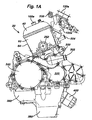
- Figures 1A to 1E Five external views of a preferred embodiment are shown in Figures 1A to 1E , which are respectively a right side elevation, a left side elevation, a front elevation, a rear elevation and a plan view of the engine.
- the engine is a four-stroke engine 20 comprising three cylinders 80a, 80b, 80c in an in-line configuration, each having a bore and stroke of 88mm and 49.3mm respectively.
- This oversquare shape may enable the engine to be run at higher speeds.
- the combustion chamber of each cylinder (defined by the shape of the cylinder head and the piston crown, and preferably substantially hemispherical) has a size giving rise to a compression ratio of 12:1 to 13:1 or higher.
- the compression ratio is 1,3:1 to 14:1 or higher.
- the engine comprises an engine casing 22, and a cylinder head cover 40 detachably located on a cylinder head 60.
- the cylinder head 60 comprises three inlet apertures 70a, 70b, 70c which are disposed (in contrast to known production and road motorcycles) on its forward side 62. Attached to the inlet apertures 70 (in an elastic manner, in a preferred embodiment) are respective throttle bodies 100a, 100b, 100c having respective intake trumpets 120a, 120b, 120c. Each intake aperture 70, throttle body 100 and trumpet 120 feeds a respective cylinder 80 as further described below.
- In the rear side 64 of the cylinder head 60 are disposed three exhaust apertures 200a, 200b, 200c to which are attached respective exhaust passages (not shown).
- the exhaust apertures 200 are fed by the combustion chambers 82 via two exhaust ports (not shown) per cylinder as further described bellow.
- the exhaust system and the intake system may be disposed at a distance from one another which may overcome or alleviate the problem in known engines in which the intake air is heated by the exhaust gases due to the proximity of the systems to one another.
- the exhaust system is remote from the coolant and lubricant radiators (described below) which may result in less heat transfer from the exhaust system to the radiators.
- the cylinders are angled back from the vertical by 15°. In further embodiments this angle is between 13.5° and 16.5°, and in still further embodiments, it is between 12° and 18°. In yet further embodiments the angle is up to 20° or 25°.
- the inlet trumpets 120 point upwards to a greater degree.
- the engine may be located further forward than in known motorcycles allowing for more flexibility in the location of the centre of gravity.
- the cylinder head 60 houses two camshafts 240a, 240b driving two inlet and two exhaust valves per cylinder.
- the valve train is described in further detail below.
- the cylinders are each lined by a respective removeable cylinder liner.
- the use of separate liners may reduce the likelihood of distortion, and such liners may be manufactured, removed and replaced independently of one another and of the cylinder head/engine block and may provide a more reliable solution. Furthermore, the liners may be removed and the engine block reused.
- a water pump 300 for pumping coolant around the engine.
- the engine casing 22 comprises a removable crankshaft casing 320, a removable clutch casing 340 and an aperture for a removable sealed gearbox magazine 420.
- An oil pump is mounted within a portion 360 of the engine casing.
- the oil pump draws oil from a sump 380.
- An oil filter 400 is provided. The lubrication system is described in further detail below.
- the engine 20 comprises a crankshaft 440 (see Figures 2 , 3 , 4 and 5A to C ).
- the engine has an even firing order and the three crank pins 448a, b, c on the crankshaft 440 are equally spaced such that forces due to acceleration of reciprocating components are lately balanced in a known manner, either by each other or by extended webs 442 (which in a preferred embodiment comprise heavy metal inserts) on the crankshaft.
- extended webs 442 which in a preferred embodiment comprise heavy metal inserts
- the outside two cylinders 80a, 80c produce an additional torque on the crankshaft which is not cancelled by the reciprocating masses of the pistons or by, the rotating masses of the extended webs 442.
- the engine 20 comprises a balancing shaft 460.
- the balancing shaft is driven by engagement of a gear 464 on the balancing shaft 460 and a gear 444 on the crankshaft 440.
- the balancing shaft driving gears 444, 464 have the same size (38 teeth) such that the balancing shaft 460 rotates at the same speed as the crankshaft 440.
- the balancing, shaft comprises two balancing masses: the first mass 466 is adjacent the gear 464, and the second mass 468 (which may contain inserts 470 of denser material) is adjacent the end of the balancing shaft remote from the gear 464.
- the second mass 468 is adjacent a balancing shaft primary gear 472 on the balancing shaft.
- the balancing shaft primary gear 472 is arranged mesh with a clutch primary gear (as described below with reference to Figure 12).
- the first and second masses 466, 468 are disposed on opposing sides of the balancing shaft 460.
- a further balancing mass is provided by the gear wheels 464, 472. These have one or more cavities or bores (eg. 474 in the gear 464) so as to displace the centre of gravity of the gear wheel from its axis of rotation.
- the webs on the crankshaft have a mass designed to balance the centrifugal forces on the crankshaft to an extent of 50%. This may allow for the use of a small, light crankshaft which is inexpensive to produce and which has low inertia.
- the crankshaft has at least two non-symmetric webs.
- the webs have a mass such that they balance 100% of the centrifugal forces.
- the balancing shaft 460 is located above the sump, in contrast to known system using a balancing shaft in which the shaft is located forward of the crankshaft and in which the oil pump is located above the sump. Such a configuration may give rise to a shorter engine length.
- the balancing-shaft-mounted balancing shaft driving gear 464 has a radius greater than that of the further gear 472 (which has 26 teeth).
- the radius of the second mass 468 is greater than the radius of the further gear 472 (and in particular, the radius of the second mass 468 is greater than the radius of the dedendum circle of the balancing shaft primary gear 472). This may be achieved for example by forming the balancing shaft 460 as an assembly.
- the balancing shaft primary gear 472 on the balancing shaft 460 engages with the clutch primary gear 482. For this reason and since in the preferred embodiment the gearbox 420 is rearward of the crankshaft 440, the balancing shaft 460 is to the rear, and higher than, the crankshaft 440.
- the engine casing 22 has a single split (not shown) at approximately the level of the shafts to allow for easy assembly and disassembly.
- FIG. 6 is a schematic diagram of the power train beginning at the engine 20.
- the cylinders 80 turn the crankshaft 440, which in turn drives the balancing shaft via meshing gears 444, 464.
- the balancing shaft drives the primary drive which comprises the balancing shaft primary gear 472 and the clutch primary gear 482.
- This arrangement means that, in order for the sprocket 422 to turn in the correct sense, the crankshaft must turn in the opposite sense to the rotation of the wheels of the motorcycle, in contrast to known motorcycles in which the crankshaft and the gearbox output shaft rotate in the same sense.
- Such an arrangement may confer the advantage that the rotation of the crankshaft against its inertia serves to increase the downward force on the front wheel of the motorcycle (rather than reducing it as in known motorcycles) resulting in an ability to accelerate a faster rate before the front tyre of the motorcycle leaves the ground.
- the effect is such that an effective mass of approximately 1.5kg is added to the load on the front wheel, which corresponds to an increase of approximately 3 to 4% resulting in an corresponding increase in the acceleration possible before the front wheel leaves the ground.
- Figure 2A shows an end view of the shafts in the engine.
- Figure 2B is a sectional view of the arrangement shown in Figure 2A .
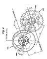
- the gears by which the balancing shaft is driven (that is the gear 444 on the crankshaft 440 and the gear 464 on the balancing shaft 460) have the same number of teeth: 38 in the embodiment shown in Figure 2 .
- the balancing shaft mounted primary gear 472 is smaller than the gear 464 by which the balancing shaft is, driven, having 26 teeth in the embodiment shown. This gear 472 meshes with the clutch primary gear 482 (which has 53 teeth).
- the gearbox input shaft 484 is driven at a speed slightly less than half that of the crankshaft. It is worthy of note that to achieve this same reduction having the clutch driven directly by the crankshaft, the clutch primary gear would have approximately double the diameter of that shown in this embodiment. The final reduction in speed is achieved by a difference in size between the output sprocket 422 and the rear wheel sprocket
- the lubrication system 600 comprises a lubrication circuit 620 and an oil cooling circuit 640.
- Oil is pumped from an oil sump 380 into the lubrication circuit 620 inside the engine by an oil pump 622 (preferably a positive-displacement volumetric pump).
- the oil pump 622 comprises a drive shaft (not shown) carrying a gear which is driven by the clutch primary (input) gear.
- the oil pump pumps oil, via an oil filter, into the lubrication circuit From the oil filter, oil flows to a main gallery 630, from where lubrication is provided to the crankshaft and to oil jets which spray oil under the pistons.
- the main gallery also feeds the cylinder head and second gallery 632 from where lubrication is provided to the balancing shaft.
- Oil is pumped to the clutch primary gear (via a conduit formed by a longitudinal bore 1400 passing through the gearbox input shaft 484) and clutch (not shown). Restrictors are provided upstream of the oil jets, the cylinder head and the clutch primary gear to reduce the oil pressure and rate of flow. Oil from the various lubricated surfaces eventually returns to the oil sump 380.
- a pressure relief valve 624 is located in the lubrication circuit close to the oil pump 622.
- the pressure relief valve is adapted to prevent the oil pressure in the lubrication system rising above a specific threshold.
- the threshold lies in the region of between 3 and 6 bar (between 3x10 5 Pa and 6x10 5 Pa) In particularly preferred embodiments, the threshold is in the region of 4 to 5 bar (4x10 5 Pa to 5x10 5 Pa).
- the pressure relief valve 624 comprises a relief outlet connected via a conduit 626, for example in the preferred embodiment a pipe, to the oil cooling circuit 640, and a spring preloaded piston moveable from a closed position to an open position in which it allows oil to escape via an orifice in the relief outlet.
- the pressure relief valve 624 opens, allowing some oil to pass via the relief outlet into the conduit 626 and from there into the oil cooling circuit 640. This has the effect of reducing the oil pressure in the lubrication circuit 620.
- the pressure relief valve closes, preventing further oil from escaping into the oil cooling circuit
- the oil cooling circuit 640 comprises a heat exchanger or radiator mounted near the engine on the motorcycle. Oil flowing through the oil cooling circuit 640 is cooled and returned to the sump 380 from where it is pumped back into the lubrication circuit by the oil pump 622. Since the oil cooling circuit is open to the sump, the oil pressure in the oil cooing circuit is low.
- the oil pump 622 is driven by the clutch primary gear (482 in Figure 6 ), and the volume of oil it generates is proportional to the engine speed.
- the oil pressure produced by the pump depends on the resistance of the lubrication circuits downstream of the pump to the flow generated by the pump.
- the oil pump does not generate sufficient oil pressure for any oil to escape via the pressure relief valve into the oil cooling circuit. This, however, does not present a problem since, at low engine speeds, the engine is generating less heat, and hence the oil, will be relatively cool.
- the temperature of the engine and the oil will generally be higher. Once the engine reaches a speed sufficient to cause the oil pressure to rise above the threshold of the pressure relief valve 624 (at approximately 4000 rpm), the pressure relief valve opens and allows some oil into the oil cooling circuit 640 to be cooled.
- the oil cooling system is only used when needed.
- the oil pump pumps more oil, thus generating higher oil pressure.
- the amount of oil fed to the oil cooling circuit is determined by the oil pressure generated by the oil pump, and is hence related to the engine speed. Since the engine speed also partially determines the temperature of the engine (and hence of the oil), an indirect relationship exists between the oil temperature and the amount of oil passing through the oil cooling circuit. This provides for a lubrication system in which oil temperature is automatically regulated dependent upon engine speed.
- the oil cooling circuit is separated from the lubrication circuit by the pressure relief valve, the oil pressure in the oil cooling circuit is also always significantly lower than the oil pressure in the lubrication circuit. This can mean that damage to the exposed parts of the lubrication system as a whole (for example, the radiator and connecting pipes) does not result in a sudden and catastrophic loss of oil. For example, debris such as stones flung up from the road surface by the front wheel of the motorcycle might puncture the oil cooling radiator. If the oil in the radiator were at high pressure, all of the oil soon would be lost, immediately disabling the motorcycle. In contrast, a slow leak under low pressure may give the rider sufficient time to proceed to his destination or to a garage before all oil is lost.
- the oil pump 622 is located below the gearbox to the rear of the sump 380. This allows for the balancing shaft (460 in Figure 12 for example) to be positioned above the sump as described elsewhere.
- the oil pump 622 draws oil from the sump 380 through a strainer 382.
- a baffle 662 is located between the sump 380 and the oil pump portion 3 60 of the engine casing.
- the sump itself is relatively deep.
- the deep sump in conjunction with the baffle prevents or inhibits oil from leaving the sump under acceleration and in the event that the front of the motorcycle is raised off the ground, resulting in the engine being at an angle to the normal upright position shown. It is thereby ensured that sufficient oil remains in the sump to be pumped into the lubricating circuit in such circumstances.
- the baffle together with the internal walls of the engine casing form a cavity with a forward facing opening (enclosed within the engine casing), such that if the engine should be inclined backwards, the cavity fills with oil.
- an additional/alternative baffle is provided towards the front of the sump, for preventing or inhibiting oil from leaving the sump under deceleration.
- baffles there are disposed in the sump a plurality of baffles generally arranged to inhibit movement of the oil in the sump.
- a further baffle 663 is provided which prevents the gases being expelled from the bottom end of the cylinders on the down stroke of the respective pistons from passing directly into the sump and causing the oil in the sump to be displaced or to foam.
- the depth and shape of the sump is substantially as shown for example in Figures 1 and 2 .
- the lubrication system described provides lubrication to all parts of the engine excluding the gearbox.
- the gearbox is a self-contained separately lubricated unit as shown in Figure 6 .
- the engine 20 (including the balancing shaft 460 and the balancing shaft primary gear 472) and the clutch primary gear 482, are lubricated by the lubrication system 600 as described above.
- gearbox With the exception of the driven end of the gearbox input shaft 484, the gearbox is enclosed entirely in a gearbox casing. An oil bath is provided inside the gearbox 420. The motion of the gears dipping into the oil bath generates an oil mist which is spread throughout the gearbox, ensuring sufficient lubrication of components within the gearbox, as known per se.
- the gearbox is constructed as an extractable constant-mesh magazine.
- the gearbox comprises an input shaft 484 (or mainshaft) driven by a clutch 480 and an output shaft 486 (or countershaft).
Landscapes
- Engineering & Computer Science (AREA)
- Mechanical Engineering (AREA)
- Chemical & Material Sciences (AREA)
- Combustion & Propulsion (AREA)
- General Engineering & Computer Science (AREA)
- Transportation (AREA)
- Sustainable Energy (AREA)
- Sustainable Development (AREA)
- Life Sciences & Earth Sciences (AREA)
- Manufacturing & Machinery (AREA)
- Automatic Cycles, And Cycles In General (AREA)
- Lubrication Of Internal Combustion Engines (AREA)
- General Details Of Gearings (AREA)
- Exhaust Silencers (AREA)
- Lubrication Details And Ventilation Of Internal Combustion Engines (AREA)
- Automobile Manufacture Line, Endless Track Vehicle, Trailer (AREA)
Description
- The present invention relates to a motorcycle engine. In particular the invention relates to the layout of shafts in a three-cylinder motorcycle engine.
- The use of engines having three cylinders in motorcycles is known; it is also known that first order forces caused by the inertia of the pistons in such an engine may be balanced by using a balancing shaft with appropriate out-of-balance masses and driven such that it rotates at the same speed as the crankshaft. However, the inclusion of an additional shaft in the crankcase increases the weight, complexity and cost of the engine. The present invention seeks to mitigate this disadvantage by utilising the balancing shaft for additional purposes.
- There is therefore provided a motorcycle engine comprising a crankshaft which drives a balancing shaft, which in turn drives a gearbox input, the balancing shaft being arranged such that the gearbox input rotates more slowly than the crankshaft.
- Providing speed-reduction gearing between the crankshaft and the gearbox input via a balancing shaft reduces the need for further overall speed reduction in the gearbox and final drive train (which may be via a chain, belt or shaft). In particular, reducing the need for speed reduction in a chain or belt drive can permit a smaller rear sprocket or pulley. This can reduce unsprung weight, reduce chain length (and hence stretching over time) and can also permit greater freedom in the design of the rear suspension.
- The term "gearbox" is used herein to include any form of variable-ratio transmission, whether or not enclosed in a box or casing.
- Preferably, the balancing shaft comprises a first gear by which it is driven and a second gear by which it drives the gearbox input, the first gear being larger than the second gear. In a particularly preferred embodiment, the second gear comprises n teeth and the first gear comprises at least 1.5n and preferably at least 2n teeth.
- The balance shaft may drive the gearbox input via a clutch.
- In the preferred embodiments, the required speed reduction may be achieved without the requirement for a particularly small gear on the crankshaft (which would be constrained by the throws of the cranks) or a particularly large clutch primary gear (which would increase the size of the engine).
- Preferably, the crankshaft rotates in the opposite sense to the gearbox output For example, the engine may comprise only four shafts: crankshaft, balancing shaft, gearbox input shaft and countershaft (output shaft). The counter-rotation of the crankshaft may afford increased acceleration before the front wheel of the motorcycle leaves the ground by virtue of a torque reaction. It may also result in reduced gyroscopic forces on the motorcycle, because the engine and wheels rotate in opposite directions about parallel axes.
- In embodiments comprising only one cylinder or only one bank of cylinders, the cylinder or bank of cylinders is preferably inclined towards the rear of the engine. This may allow the engine to be situated further forwards in the motorcycle.
- A balancing mass of the balancing shaft may be disposed adjacent a said gear. A said gear may itself constitute a balancing mass.
- The engine may include an oil pump driven via the balancing shaft. The oil pump may be driven via a primary gear of the clutch.
- Preferably the oil pump is disposed to the rear of a sump of the engine, and the balancing shaft is disposed above the sump to the rear of the crankshaft.
- Specific embodiments will now be described, by way of example only, with reference to the accompanying drawings, in which:
-
Figure 1A is right side elevation of the engine; -
Figure 1B is a left side elevation of the engine shown inFigure 1A ; -
Figure 1C is a front elevation of the engine shown in theFigures 1A and1B ; -
Figure 1D is a rear elevation of the engine shown inFigures 1A to 1C ; -
Figure 1E is a plan view of the engine shown inFigures 1A to 1 D; -
Figure 2A is an end view of the shafts in the engine (including the gearbox); -
Figure 2B is a sectional view of the arrangement shown inFigure 2A ; -
Figure 3 shows a crankshaft and a balancing shaft of an engine; -
Figure 4 shows the gears by which the crankshaft of an engine drives the balancing shaft; -
Figure 5A is an elevation of the driven end of the balancing shaft of an engine, showing the gear by which the balancing shaft is driven; -
Figure 5B is a longitudinal cross-section of the balancing shaft of an engine; -
Figure 5C is a perspective view of the balancing shaft shown inFigure 5B ; -
Figure 6 is a schematic representation of the power train of a motorcycle; -
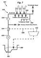
Figure 7 is a schematic representation of the lubrication system of an engine; and -
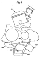
Figure 8 shows the position of elements of a lubrication system with respect to an engine. - Five external views of a preferred embodiment are shown in
Figures 1A to 1E , which are respectively a right side elevation, a left side elevation, a front elevation, a rear elevation and a plan view of the engine. - In overview, the engine is a four-
stroke engine 20 comprising threecylinders - In an embodiment intended primarily for road use, the combustion chamber of each cylinder (defined by the shape of the cylinder head and the piston crown, and preferably substantially hemispherical) has a size giving rise to a compression ratio of 12:1 to 13:1 or higher. In a further embodiment intended for racing, for example in the World Superbikes Competition, the compression ratio is 1,3:1 to 14:1 or higher.
- The engine comprises an
engine casing 22, and acylinder head cover 40 detachably located on acylinder head 60. Thecylinder head 60 comprises three inlet apertures 70a, 70b, 70c which are disposed (in contrast to known production and road motorcycles) on its forward side 62. Attached to the inlet apertures 70 (in an elastic manner, in a preferred embodiment) arerespective throttle bodies respective intake trumpets respective cylinder 80 as further described below. In therear side 64 of thecylinder head 60 are disposed threeexhaust apertures - Having the inlet apertures on the forward side of the engine and the exhaust apertures to the rear may allow the exhaust system and the intake system to be disposed at a distance from one another which may overcome or alleviate the problem in known engines in which the intake air is heated by the exhaust gases due to the proximity of the systems to one another. In addition, the exhaust system is remote from the coolant and lubricant radiators (described below) which may result in less heat transfer from the exhaust system to the radiators. The cylinders are angled back from the vertical by 15°. In further embodiments this angle is between 13.5° and 16.5°, and in still further embodiments, it is between 12° and 18°. In yet further embodiments the angle is up to 20° or 25°. As a result, the inlet trumpets 120 point upwards to a greater degree. As a further result, the engine may be located further forward than in known motorcycles allowing for more flexibility in the location of the centre of gravity.
- The
cylinder head 60 houses twocamshafts - The cylinders are each lined by a respective removeable cylinder liner. The use of separate liners may reduce the likelihood of distortion, and such liners may be manufactured, removed and replaced independently of one another and of the cylinder head/engine block and may provide a more reliable solution. Furthermore, the liners may be removed and the engine block reused.
- Mounted on the right side of the cylinder block 24 is a
water pump 300 for pumping coolant around the engine. - The
engine casing 22 comprises aremovable crankshaft casing 320, a removableclutch casing 340 and an aperture for a removable sealedgearbox magazine 420. - An oil pump is mounted within a
portion 360 of the engine casing. The oil pump draws oil from asump 380. Anoil filter 400 is provided. The lubrication system is described in further detail below. - The
engine 20 comprises a crankshaft 440 (seeFigures 2 ,3 ,4 and5A to C ). The engine has an even firing order and the three crankpins 448a, b, c on thecrankshaft 440 are equally spaced such that forces due to acceleration of reciprocating components are lately balanced in a known manner, either by each other or by extended webs 442 (which in a preferred embodiment comprise heavy metal inserts) on the crankshaft. However, the outside twocylinders extended webs 442. - To counter this torque, the
engine 20 comprises a balancingshaft 460. The balancing shaft is driven by engagement of agear 464 on the balancingshaft 460 and agear 444 on thecrankshaft 440. The balancing shaft driving gears 444, 464 have the same size (38 teeth) such that the balancingshaft 460 rotates at the same speed as thecrankshaft 440. - The balancing, shaft comprises two balancing masses: the
first mass 466 is adjacent thegear 464, and the second mass 468 (which may containinserts 470 of denser material) is adjacent the end of the balancing shaft remote from thegear 464. In a particularly preferred embodiment in which the balancing shaft is used to drive the gearbox input shaft via the clutch, thesecond mass 468 is adjacent a balancing shaftprimary gear 472 on the balancing shaft. The balancing shaftprimary gear 472 is arranged mesh with a clutch primary gear (as described below with reference to Figure 12). - As can be seen (for example, in
Figure 5B ), the first andsecond masses shaft 460. In addition to the effect of the first andsecond masses gear wheels - In a preferred embodiment, the webs on the crankshaft have a mass designed to balance the centrifugal forces on the crankshaft to an extent of 50%. This may allow for the use of a small, light crankshaft which is inexpensive to produce and which has low inertia. In preferred refinements of this embodiment, the crankshaft has at least two non-symmetric webs. In a further preferred embodiment, the webs have a mass such that they balance 100% of the centrifugal forces.
- In a particularly preferred embodiment (such as that shown in the Figures), the balancing
shaft 460 is located above the sump, in contrast to known system using a balancing shaft in which the shaft is located forward of the crankshaft and in which the oil pump is located above the sump. Such a configuration may give rise to a shorter engine length. - In a particularly preferred embodiment, the balancing-shaft-mounted balancing
shaft driving gear 464 has a radius greater than that of the further gear 472 (which has 26 teeth). - Additionally, the radius of the
second mass 468 is greater than the radius of the further gear 472 (and in particular, the radius of thesecond mass 468 is greater than the radius of the dedendum circle of the balancing shaft primary gear 472). This may be achieved for example by forming the balancingshaft 460 as an assembly. - As mentioned above, the balancing shaft
primary gear 472 on the balancingshaft 460 engages with the clutchprimary gear 482. For this reason and since in the preferred embodiment thegearbox 420 is rearward of thecrankshaft 440, the balancingshaft 460 is to the rear, and higher than, thecrankshaft 440. Theengine casing 22 has a single split (not shown) at approximately the level of the shafts to allow for easy assembly and disassembly. -
Figure 6 is a schematic diagram of the power train beginning at theengine 20. Thecylinders 80 turn thecrankshaft 440, which in turn drives the balancing shaft via meshing gears 444, 464. The balancing shaft drives the primary drive which comprises the balancing shaftprimary gear 472 and the clutchprimary gear 482. This arrangement means that, in order for thesprocket 422 to turn in the correct sense, the crankshaft must turn in the opposite sense to the rotation of the wheels of the motorcycle, in contrast to known motorcycles in which the crankshaft and the gearbox output shaft rotate in the same sense. Such an arrangement may confer the advantage that the rotation of the crankshaft against its inertia serves to increase the downward force on the front wheel of the motorcycle (rather than reducing it as in known motorcycles) resulting in an ability to accelerate a faster rate before the front tyre of the motorcycle leaves the ground. In a particularly preferred embodiment having a weight distribution of approximately 50% on each wheel, the effect is such that an effective mass of approximately 1.5kg is added to the load on the front wheel, which corresponds to an increase of approximately 3 to 4% resulting in an corresponding increase in the acceleration possible before the front wheel leaves the ground. -
Figure 2A shows an end view of the shafts in the engine.Figure 2B is a sectional view of the arrangement shown inFigure 2A . As indicated above, the gears by which the balancing shaft is driven (that is thegear 444 on thecrankshaft 440 and thegear 464 on the balancing shaft 460) have the same number of teeth: 38 in the embodiment shown inFigure 2 . In order to achieve in part the necessary reduction in rotational speed between the crankshaft and the rear wheel, the balancing shaft mountedprimary gear 472 is smaller than thegear 464 by which the balancing shaft is, driven, having 26 teeth in the embodiment shown. Thisgear 472 meshes with the clutch primary gear 482 (which has 53 teeth). Thus, thegearbox input shaft 484 is driven at a speed slightly less than half that of the crankshaft. It is worthy of note that to achieve this same reduction having the clutch driven directly by the crankshaft, the clutch primary gear would have approximately double the diameter of that shown in this embodiment. The final reduction in speed is achieved by a difference in size between theoutput sprocket 422 and the rear wheel sprocket - The lubrication system will now be described with reference to
Figure 7 . - The
lubrication system 600 comprises alubrication circuit 620 and anoil cooling circuit 640. - Oil is pumped from an
oil sump 380 into thelubrication circuit 620 inside the engine by an oil pump 622 (preferably a positive-displacement volumetric pump). Theoil pump 622 comprises a drive shaft (not shown) carrying a gear which is driven by the clutch primary (input) gear. The oil pump pumps oil, via an oil filter, into the lubrication circuit From the oil filter, oil flows to amain gallery 630, from where lubrication is provided to the crankshaft and to oil jets which spray oil under the pistons. The main gallery also feeds the cylinder head andsecond gallery 632 from where lubrication is provided to the balancing shaft. Oil is pumped to the clutch primary gear (via a conduit formed by a longitudinal bore 1400 passing through the gearbox input shaft 484) and clutch (not shown). Restrictors are provided upstream of the oil jets, the cylinder head and the clutch primary gear to reduce the oil pressure and rate of flow. Oil from the various lubricated surfaces eventually returns to theoil sump 380. - A
pressure relief valve 624 is located in the lubrication circuit close to theoil pump 622. The pressure relief valve is adapted to prevent the oil pressure in the lubrication system rising above a specific threshold. In preferred embodiments, the threshold lies in the region of between 3 and 6 bar (between 3x10⁵ Pa and 6x10⁵ Pa) In particularly preferred embodiments, the threshold is in the region of 4 to 5 bar (4x10⁵ Pa to 5x10⁵ Pa). Thepressure relief valve 624 comprises a relief outlet connected via a conduit 626, for example in the preferred embodiment a pipe, to theoil cooling circuit 640, and a spring preloaded piston moveable from a closed position to an open position in which it allows oil to escape via an orifice in the relief outlet. - When the oil pressure in the
lubrication circuit 620 exceeds the specific threshold, thepressure relief valve 624 opens, allowing some oil to pass via the relief outlet into the conduit 626 and from there into theoil cooling circuit 640. This has the effect of reducing the oil pressure in thelubrication circuit 620. When the oil pressure in the lubrication circuit falls below the specific threshold, the pressure relief valve closes, preventing further oil from escaping into the oil cooling circuit - In a preferred embodiment, the
oil cooling circuit 640 comprises a heat exchanger or radiator mounted near the engine on the motorcycle. Oil flowing through theoil cooling circuit 640 is cooled and returned to thesump 380 from where it is pumped back into the lubrication circuit by theoil pump 622. Since the oil cooling circuit is open to the sump, the oil pressure in the oil cooing circuit is low. - The
oil pump 622 is driven by the clutch primary gear (482 inFigure 6 ), and the volume of oil it generates is proportional to the engine speed. For a given oil temperature, the oil pressure produced by the pump depends on the resistance of the lubrication circuits downstream of the pump to the flow generated by the pump. At low engine speeds (for example at an idling speed of around 1000 rpm), the oil pump does not generate sufficient oil pressure for any oil to escape via the pressure relief valve into the oil cooling circuit. This, however, does not present a problem since, at low engine speeds, the engine is generating less heat, and hence the oil, will be relatively cool. - At higher engine speeds, the temperature of the engine and the oil will generally be higher. Once the engine reaches a speed sufficient to cause the oil pressure to rise above the threshold of the pressure relief valve 624 (at approximately 4000 rpm), the pressure relief valve opens and allows some oil into the
oil cooling circuit 640 to be cooled. - In this manner, the oil cooling system is only used when needed. At higher engine speeds the oil pump pumps more oil, thus generating higher oil pressure. The amount of oil fed to the oil cooling circuit is determined by the oil pressure generated by the oil pump, and is hence related to the engine speed. Since the engine speed also partially determines the temperature of the engine (and hence of the oil), an indirect relationship exists between the oil temperature and the amount of oil passing through the oil cooling circuit. This provides for a lubrication system in which oil temperature is automatically regulated dependent upon engine speed.
- Because the oil cooling circuit is separated from the lubrication circuit by the pressure relief valve, the oil pressure in the oil cooling circuit is also always significantly lower than the oil pressure in the lubrication circuit. This can mean that damage to the exposed parts of the lubrication system as a whole (for example, the radiator and connecting pipes) does not result in a sudden and catastrophic loss of oil. For example, debris such as stones flung up from the road surface by the front wheel of the motorcycle might puncture the oil cooling radiator. If the oil in the radiator were at high pressure, all of the oil soon would be lost, immediately disabling the motorcycle. In contrast, a slow leak under low pressure may give the rider sufficient time to proceed to his destination or to a garage before all oil is lost.
- The arrangement of elements of the lubrication system will now be described in more detail with reference to
Figure 8 , which shows a schematic of elements of the lubrication system in relation to a simplified outline of theengine 16. - In contrast to conventional motorcycle engines where the oil pump is often located just above the sump, in a preferred embodiment, the
oil pump 622 is located below the gearbox to the rear of thesump 380. This allows for the balancing shaft (460 in Figure 12 for example) to be positioned above the sump as described elsewhere. - In a preferred embodiment, the
oil pump 622 draws oil from thesump 380 through astrainer 382. - In a particular embodiment, a
baffle 662 is located between thesump 380 and theoil pump portion 3 60 of the engine casing. The sump itself is relatively deep. The deep sump in conjunction with the baffle prevents or inhibits oil from leaving the sump under acceleration and in the event that the front of the motorcycle is raised off the ground, resulting in the engine being at an angle to the normal upright position shown. It is thereby ensured that sufficient oil remains in the sump to be pumped into the lubricating circuit in such circumstances. In a particularly preferred embodiment, the baffle together with the internal walls of the engine casing form a cavity with a forward facing opening (enclosed within the engine casing), such that if the engine should be inclined backwards, the cavity fills with oil. - In further embodiments, an additional/alternative baffle is provided towards the front of the sump, for preventing or inhibiting oil from leaving the sump under deceleration.
- In a further preferred embodiment, there are disposed in the sump a plurality of baffles generally arranged to inhibit movement of the oil in the sump.
- A
further baffle 663 is provided which prevents the gases being expelled from the bottom end of the cylinders on the down stroke of the respective pistons from passing directly into the sump and causing the oil in the sump to be displaced or to foam. - In a further preferred embodiment, the depth and shape of the sump is substantially as shown for example in
Figures 1 and2 . - In a preferred embodiment, the lubrication system described provides lubrication to all parts of the engine excluding the gearbox. The gearbox is a self-contained separately lubricated unit as shown in
Figure 6 . - The engine 20 (including the balancing
shaft 460 and the balancing shaft primary gear 472) and the clutchprimary gear 482, are lubricated by thelubrication system 600 as described above. - With the exception of the driven end of the
gearbox input shaft 484, the gearbox is enclosed entirely in a gearbox casing. An oil bath is provided inside thegearbox 420. The motion of the gears dipping into the oil bath generates an oil mist which is spread throughout the gearbox, ensuring sufficient lubrication of components within the gearbox, as known per se. - The gearbox is constructed as an extractable constant-mesh magazine. The gearbox comprises an input shaft 484 (or mainshaft) driven by a clutch 480 and an output shaft 486 (or countershaft).
- Statements in this specification of the "objects of the invention" relate to preferred embodiments of the invention, but not necessarily to all embodiments of the invention falling within the claims
- The description of the invention with reference to the drawings is by way of example only.
Claims (11)
- A motorcycle engine comprising a crankshaft which drives a balancing shaft, which in turn drives a gearbox input, the balancing shaft being arranged such that the gearbox input rotates more slowly than the crankshaft.
- An engine according to claim 1, wherein the balancing shaft comprises a first gear by which it is driven and a second gear by which it drives the gearbox input, the first gear being larger than the second gear.
- An engine according to claim 2, wherein the second gear comprises n teeth and the first gear comprises at least 1.5n and preferably at least 2n teeth.
- An engine according to any of claims 1 to 3, wherein the balancing shaft drives the gearbox input via a clutch.
- An engine according to any of the preceding claims, further comprising a gearbox output for driving a rear wheel of a motorcycle, wherein the crankshaft rotates in the opposite sense to the gearbox output.
- An engine according to any of the preceding claims, comprising only one cylinder or only one bank of cylinders, wherein the cylinder or bank of cylinders is inclined towards the rear of the engine.
- An engine according to claim 2, wherein a balancing mass of the balancing shaft is disposed adjacent a said gear.
- An engine according to claim 2, wherein a said gear itself constitutes a balancing mass.
- An engine according to any preceding claim comprising an oil pump driven via the balancing shaft.
- An engine according to claims, 4 and 9, wherein the oil pump is driven via a primary gear of the clutch.
- An engine according to claim 9 or 10, wherein the oil pump is disposed to the rear of a sump of the engine, and the balancing shaft is disposed above the sump to the rear of the crankshaft.
Applications Claiming Priority (15)
| Application Number | Priority Date | Filing Date | Title |
|---|---|---|---|
| GB0213123 | 2002-06-07 | ||
| GBGB0213123.3A GB0213123D0 (en) | 2002-06-07 | 2002-06-07 | Motorcycle |
| GBGB0213120.9A GB0213120D0 (en) | 2002-06-07 | 2002-06-07 | Motorcycle and engine balancing shaft chassis cooling system lubrication syste and swingarm therefor |
| GB0213136A GB0213136D0 (en) | 2002-06-07 | 2002-06-07 | Automotive attachments |
| GB0213136 | 2002-06-07 | ||
| GB0213118 | 2002-06-07 | ||
| GB0213118A GB0213118D0 (en) | 2002-06-07 | 2002-06-07 | Exhaust system |
| GB0213120 | 2002-06-07 | ||
| GB0213370A GB0213370D0 (en) | 2002-06-11 | 2002-06-11 | Motorcycle |
| GB0213370 | 2002-06-11 | ||
| GBGB0217153.6A GB0217153D0 (en) | 2002-06-07 | 2002-07-24 | Motorcycle and engine balancing shaft chassis cooling system lubrication system and swingarm therefor |
| GB0217153 | 2002-07-24 | ||
| GB0301704 | 2003-01-24 | ||
| GB0301704A GB0301704D0 (en) | 2002-06-07 | 2003-01-24 | Motorcycle |
| PCT/GB2003/002468 WO2003104627A1 (en) | 2002-06-07 | 2003-06-06 | Motorcycle engine |
Publications (2)
| Publication Number | Publication Date |
|---|---|
| EP1523614A1 EP1523614A1 (en) | 2005-04-20 |
| EP1523614B1 true EP1523614B1 (en) | 2009-10-28 |
Family
ID=29741208
Family Applications (2)
| Application Number | Title | Priority Date | Filing Date |
|---|---|---|---|
| EP03738271A Expired - Lifetime EP1525135B1 (en) | 2002-06-07 | 2003-06-06 | Motorcycle engine |
| EP03738265A Expired - Lifetime EP1523614B1 (en) | 2002-06-07 | 2003-06-06 | Motorcycle engine |
Family Applications Before (1)
| Application Number | Title | Priority Date | Filing Date |
|---|---|---|---|
| EP03738271A Expired - Lifetime EP1525135B1 (en) | 2002-06-07 | 2003-06-06 | Motorcycle engine |
Country Status (6)
| Country | Link |
|---|---|
| EP (2) | EP1525135B1 (en) |
| JP (2) | JP2005529275A (en) |
| KR (1) | KR101003453B1 (en) |
| AU (4) | AU2003274781A1 (en) |
| GB (1) | GB2393942B (en) |
| WO (4) | WO2003104075A1 (en) |
Families Citing this family (13)
| Publication number | Priority date | Publication date | Assignee | Title |
|---|---|---|---|---|
| JP5189846B2 (en) * | 2007-02-01 | 2013-04-24 | ヤマハ発動機株式会社 | vehicle |
| ITMI20070231A1 (en) * | 2007-02-08 | 2008-08-09 | Mv Agusta Motor S P A | MOTOR SUCTION SYSTEM FOR MOTORBIKE |
| ITMI20070845A1 (en) * | 2007-04-23 | 2008-10-24 | Piaggio & C Spa | FRAME FOR MOTORCYCLES WITH ADJUSTABLE PITCH |
| ITMI20070846A1 (en) * | 2007-04-23 | 2008-10-24 | Piaggio & C Spa | COMPACT FRAME FOR MOTORCYCLE WITH AIR INTAKE FOR INTEGRATED AIRBOX |
| JP4890409B2 (en) * | 2007-09-29 | 2012-03-07 | 本田技研工業株式会社 | Power unit for small vehicles |
| WO2009044669A1 (en) | 2007-09-29 | 2009-04-09 | Honda Motor Co., Ltd. | Power unit for small-sized vehicle |
| JP5339603B2 (en) * | 2009-03-30 | 2013-11-13 | 本田技研工業株式会社 | Motorcycle |
| CN102410103B (en) * | 2011-09-30 | 2013-05-01 | 洛阳北方企业集团有限公司 | Crankcase structure of motorcycle engine |
| JP6160335B2 (en) * | 2013-07-29 | 2017-07-12 | スズキ株式会社 | Parallel multi-cylinder engine |
| JP5770238B2 (en) * | 2013-09-27 | 2015-08-26 | 本田技研工業株式会社 | Vehicle exhaust structure |
| CN103994178A (en) * | 2014-05-30 | 2014-08-20 | 徐亚珍 | Motorcycle balance shaft gear assembly |
| CN105172938B (en) * | 2015-08-15 | 2017-05-24 | 安徽安凯汽车股份有限公司 | Installation tool for liquefied natural gas (LNG) bottle of passenger car |
| CN108361130B (en) * | 2018-01-26 | 2023-08-25 | 重庆隆鑫机车有限公司 | High-position air inlet air filtering system and tricycle |
Family Cites Families (27)
| Publication number | Priority date | Publication date | Assignee | Title |
|---|---|---|---|---|
| US2658135A (en) * | 1951-11-21 | 1953-11-03 | Anderson L Woolfolk | Detachable light |
| US3943909A (en) * | 1974-04-26 | 1976-03-16 | Palmer Howard J | Oil cooling system |
| US3942027A (en) * | 1974-05-24 | 1976-03-02 | Raoul Fima | Internally mounted battery jump cables |
| JPS58126271A (en) * | 1982-01-20 | 1983-07-27 | 本田技研工業株式会社 | Trunk device for small-sized car |
| US4426965A (en) * | 1982-02-11 | 1984-01-24 | Cummins Engine Company, Inc. | Unitized oil cooler and filter assembly |
| AU1167583A (en) * | 1982-02-18 | 1983-08-25 | Simunek, G. | Battery jump leads |
| DE3782571T2 (en) * | 1986-07-29 | 1993-03-25 | Honda Motor Co Ltd | MOTORCYCLE-LIKE VEHICLE. |
| AU615214B2 (en) * | 1987-09-25 | 1991-09-26 | Honda Giken Kogyo Kabushiki Kaisha | Motor scooter |
| JPH01115795A (en) * | 1987-10-30 | 1989-05-09 | Suzuki Motor Co Ltd | Suction system for motorcycle |
| JPH0221045A (en) * | 1988-07-06 | 1990-01-24 | Honda Motor Co Ltd | Balancer device for internal combustion engine |
| JPH0267417A (en) * | 1988-08-31 | 1990-03-07 | Yamaha Motor Co Ltd | Exhaust controller of motorcycle |
| JP2537275B2 (en) * | 1988-09-19 | 1996-09-25 | 本田技研工業株式会社 | Motorcycle assembly method and device |
| JPH02114592U (en) * | 1989-02-28 | 1990-09-13 | ||
| EP0448728B1 (en) * | 1989-10-18 | 1994-07-27 | Honda Giken Kogyo Kabushiki Kaisha | Exhaust apparatus in saddle type vehicle |
| JP3071815B2 (en) * | 1990-10-18 | 2000-07-31 | 本田技研工業株式会社 | Engine balancer device |
| JP3018691B2 (en) * | 1991-12-24 | 2000-03-13 | スズキ株式会社 | Leg shield structure of scooter type motorcycle |
| JPH068873A (en) * | 1992-06-24 | 1994-01-18 | Suzuki Motor Corp | Motorcycle |
| JP3516464B2 (en) * | 1993-05-07 | 2004-04-05 | 本田技研工業株式会社 | Front cover for motorcycle |
| FR2705749B1 (en) * | 1993-05-28 | 1995-07-07 | Renault | Device for damping torsional vibrations in a power transmission chain. |
| JP3525949B2 (en) * | 1994-05-20 | 2004-05-10 | 本田技研工業株式会社 | Breather structure of fuel tank for straddle type vehicle |
| US5564379A (en) * | 1994-06-01 | 1996-10-15 | Volkswagen Ag | Arrangement for balancing varying moments |
| JP3578421B2 (en) * | 1995-03-03 | 2004-10-20 | 本田技研工業株式会社 | Filling pipe structure in fuel tank |
| US5820254A (en) * | 1996-01-16 | 1998-10-13 | Duenas; Mark | Removable motorcycle light |
| DE19706893A1 (en) * | 1997-02-21 | 1998-08-27 | Behr Gmbh & Co | Disc oil cooler for road vehicle engine |
| JP3088360B2 (en) * | 1997-10-02 | 2000-09-18 | 本田技研工業株式会社 | Motorcycle assembly line |
| US6281600B1 (en) * | 1999-07-01 | 2001-08-28 | Deere & Company | Jump start system for vehicles having different operating voltages |
| JP2001071968A (en) * | 1999-09-05 | 2001-03-21 | Honda Motor Co Ltd | Intake passage structure of motorcycle |
-
2003
- 2003-06-06 WO PCT/GB2003/002478 patent/WO2003104075A1/en active Application Filing
- 2003-06-06 WO PCT/GB2003/002468 patent/WO2003104627A1/en active Application Filing
- 2003-06-06 EP EP03738271A patent/EP1525135B1/en not_active Expired - Lifetime
- 2003-06-06 JP JP2004511673A patent/JP2005529275A/en active Pending
- 2003-06-06 AU AU2003274781A patent/AU2003274781A1/en not_active Abandoned
- 2003-06-06 WO PCT/GB2003/002474 patent/WO2003104071A1/en not_active Application Discontinuation
- 2003-06-06 KR KR1020047019882A patent/KR101003453B1/en not_active IP Right Cessation
- 2003-06-06 GB GB0404109A patent/GB2393942B/en not_active Expired - Fee Related
- 2003-06-06 AU AU2003244780A patent/AU2003244780A1/en not_active Abandoned
- 2003-06-06 JP JP2004511161A patent/JP2006511382A/en active Pending
- 2003-06-06 AU AU2003244787A patent/AU2003244787A1/en not_active Abandoned
- 2003-06-06 AU AU2003244773A patent/AU2003244773A1/en not_active Abandoned
- 2003-06-06 EP EP03738265A patent/EP1523614B1/en not_active Expired - Lifetime
- 2003-06-06 WO PCT/GB2003/002454 patent/WO2003104070A2/en not_active Application Discontinuation
Also Published As
| Publication number | Publication date |
|---|---|
| AU2003244780A1 (en) | 2003-12-22 |
| AU2003244787A1 (en) | 2003-12-22 |
| AU2003244773A8 (en) | 2003-12-22 |
| WO2003104075A1 (en) | 2003-12-18 |
| EP1525135B1 (en) | 2008-11-26 |
| WO2003104627A1 (en) | 2003-12-18 |
| EP1523614A1 (en) | 2005-04-20 |
| WO2003104070A2 (en) | 2003-12-18 |
| KR101003453B1 (en) | 2010-12-28 |
| WO2003104070A3 (en) | 2004-02-12 |
| WO2003104071A1 (en) | 2003-12-18 |
| WO2003104071A9 (en) | 2004-03-18 |
| KR20050025184A (en) | 2005-03-11 |
| GB0404109D0 (en) | 2004-03-31 |
| JP2006511382A (en) | 2006-04-06 |
| GB2393942A (en) | 2004-04-14 |
| JP2005529275A (en) | 2005-09-29 |
| AU2003274781A1 (en) | 2003-12-22 |
| GB2393942B (en) | 2006-11-29 |
| EP1525135A1 (en) | 2005-04-27 |
| AU2003244773A1 (en) | 2003-12-22 |
Similar Documents
| Publication | Publication Date | Title |
|---|---|---|
| CA1328588C (en) | Internal combustion engine | |
| EP0335246B1 (en) | Engine unit for motor vehicle | |
| EP1523614B1 (en) | Motorcycle engine | |
| CN1184408C (en) | Lubricating mechanism for power set | |
| EP0578267B1 (en) | Motor vehicle comprising a transverse engine | |
| US7559307B2 (en) | Oil filter mounting structure in internal combustion engine | |
| US7578277B2 (en) | Pump drive structure of water-cooled internal combustion engine | |
| US5154144A (en) | Camshaft drive arrangement for engine | |
| US7178498B2 (en) | Lubrication system for an engine | |
| US8939257B2 (en) | Power train mechanism including a surrounding member | |
| US20040112677A1 (en) | Lubricating system for power unit for vehicle with internal combustion engine | |
| US20040104075A1 (en) | Lubricating system for internal combustion engine | |
| US20040123596A1 (en) | Power unit for vehicle with internal combustion engine | |
| TWI247845B (en) | Motorcycle engine | |
| JP4372481B2 (en) | Motorcycle engine and motorcycle equipped with the engine | |
| JP2002276317A (en) | Multiple cylinder 4-cycle internal combustion engine | |
| EP0401710B1 (en) | Internal combustion engine | |
| JP4175816B2 (en) | Breather device for 4-stroke internal combustion engine | |
| JP3104484B2 (en) | Dry sump type motorcycle engine | |
| JP2005248837A (en) | Cam shaft drive gear train structure | |
| JP2881521B2 (en) | Piston for internal combustion engine | |
| JP2005248836A (en) | Internal combustion engine | |
| JP2004084603A (en) | Drysump type four-cycle engine | |
| JP2003307155A (en) | Crank case and its lubricating structure | |
| JPH10231828A (en) | Oil supply structure of two-stroke internal combustion engine |
Legal Events
| Date | Code | Title | Description |
|---|---|---|---|
| PUAI | Public reference made under article 153(3) epc to a published international application that has entered the european phase |
Free format text: ORIGINAL CODE: 0009012 |
|
| 17P | Request for examination filed |
Effective date: 20050107 |
|
| AK | Designated contracting states |
Kind code of ref document: A1 Designated state(s): AT BE BG CH CY CZ DE DK EE ES FI FR GB GR HU IE IT LI LU MC NL PT RO SE SI SK TR |
|
| AX | Request for extension of the european patent |
Extension state: AL LT LV MK |
|
| DAX | Request for extension of the european patent (deleted) | ||
| 17Q | First examination report despatched |
Effective date: 20081107 |
|
| GRAP | Despatch of communication of intention to grant a patent |
Free format text: ORIGINAL CODE: EPIDOSNIGR1 |
|
| GRAS | Grant fee paid |
Free format text: ORIGINAL CODE: EPIDOSNIGR3 |
|
| GRAA | (expected) grant |
Free format text: ORIGINAL CODE: 0009210 |
|
| AK | Designated contracting states |
Kind code of ref document: B1 Designated state(s): AT BE BG CH CY CZ DE DK EE ES FI FR GB GR HU IE IT LI LU MC NL PT RO SE SI SK TR |
|
| REG | Reference to a national code |
Ref country code: GB Ref legal event code: FG4D |
|
| REG | Reference to a national code |
Ref country code: CH Ref legal event code: EP |
|
| REG | Reference to a national code |
Ref country code: IE Ref legal event code: FG4D |
|
| REF | Corresponds to: |
Ref document number: 60329845 Country of ref document: DE Date of ref document: 20091210 Kind code of ref document: P |
|
| NLV1 | Nl: lapsed or annulled due to failure to fulfill the requirements of art. 29p and 29m of the patents act | ||
| PG25 | Lapsed in a contracting state [announced via postgrant information from national office to epo] |
Ref country code: ES Free format text: LAPSE BECAUSE OF FAILURE TO SUBMIT A TRANSLATION OF THE DESCRIPTION OR TO PAY THE FEE WITHIN THE PRESCRIBED TIME-LIMIT Effective date: 20100208 Ref country code: FI Free format text: LAPSE BECAUSE OF FAILURE TO SUBMIT A TRANSLATION OF THE DESCRIPTION OR TO PAY THE FEE WITHIN THE PRESCRIBED TIME-LIMIT Effective date: 20091028 Ref country code: PT Free format text: LAPSE BECAUSE OF FAILURE TO SUBMIT A TRANSLATION OF THE DESCRIPTION OR TO PAY THE FEE WITHIN THE PRESCRIBED TIME-LIMIT Effective date: 20100301 Ref country code: SE Free format text: LAPSE BECAUSE OF FAILURE TO SUBMIT A TRANSLATION OF THE DESCRIPTION OR TO PAY THE FEE WITHIN THE PRESCRIBED TIME-LIMIT Effective date: 20091028 |
|
| PG25 | Lapsed in a contracting state [announced via postgrant information from national office to epo] |
Ref country code: SI Free format text: LAPSE BECAUSE OF FAILURE TO SUBMIT A TRANSLATION OF THE DESCRIPTION OR TO PAY THE FEE WITHIN THE PRESCRIBED TIME-LIMIT Effective date: 20091028 Ref country code: CY Free format text: LAPSE BECAUSE OF FAILURE TO SUBMIT A TRANSLATION OF THE DESCRIPTION OR TO PAY THE FEE WITHIN THE PRESCRIBED TIME-LIMIT Effective date: 20091028 |
|
| PG25 | Lapsed in a contracting state [announced via postgrant information from national office to epo] |
Ref country code: AT Free format text: LAPSE BECAUSE OF FAILURE TO SUBMIT A TRANSLATION OF THE DESCRIPTION OR TO PAY THE FEE WITHIN THE PRESCRIBED TIME-LIMIT Effective date: 20091028 Ref country code: BE Free format text: LAPSE BECAUSE OF FAILURE TO SUBMIT A TRANSLATION OF THE DESCRIPTION OR TO PAY THE FEE WITHIN THE PRESCRIBED TIME-LIMIT Effective date: 20091028 |
|
| PG25 | Lapsed in a contracting state [announced via postgrant information from national office to epo] |
Ref country code: DK Free format text: LAPSE BECAUSE OF FAILURE TO SUBMIT A TRANSLATION OF THE DESCRIPTION OR TO PAY THE FEE WITHIN THE PRESCRIBED TIME-LIMIT Effective date: 20091028 Ref country code: RO Free format text: LAPSE BECAUSE OF FAILURE TO SUBMIT A TRANSLATION OF THE DESCRIPTION OR TO PAY THE FEE WITHIN THE PRESCRIBED TIME-LIMIT Effective date: 20091028 Ref country code: EE Free format text: LAPSE BECAUSE OF FAILURE TO SUBMIT A TRANSLATION OF THE DESCRIPTION OR TO PAY THE FEE WITHIN THE PRESCRIBED TIME-LIMIT Effective date: 20091028 Ref country code: BG Free format text: LAPSE BECAUSE OF FAILURE TO SUBMIT A TRANSLATION OF THE DESCRIPTION OR TO PAY THE FEE WITHIN THE PRESCRIBED TIME-LIMIT Effective date: 20100128 |
|
| PG25 | Lapsed in a contracting state [announced via postgrant information from national office to epo] |
Ref country code: SK Free format text: LAPSE BECAUSE OF FAILURE TO SUBMIT A TRANSLATION OF THE DESCRIPTION OR TO PAY THE FEE WITHIN THE PRESCRIBED TIME-LIMIT Effective date: 20091028 Ref country code: CZ Free format text: LAPSE BECAUSE OF FAILURE TO SUBMIT A TRANSLATION OF THE DESCRIPTION OR TO PAY THE FEE WITHIN THE PRESCRIBED TIME-LIMIT Effective date: 20091028 |
|
| PLBE | No opposition filed within time limit |
Free format text: ORIGINAL CODE: 0009261 |
|
| STAA | Information on the status of an ep patent application or granted ep patent |
Free format text: STATUS: NO OPPOSITION FILED WITHIN TIME LIMIT |
|
| 26N | No opposition filed |
Effective date: 20100729 |
|
| PG25 | Lapsed in a contracting state [announced via postgrant information from national office to epo] |
Ref country code: GR Free format text: LAPSE BECAUSE OF FAILURE TO SUBMIT A TRANSLATION OF THE DESCRIPTION OR TO PAY THE FEE WITHIN THE PRESCRIBED TIME-LIMIT Effective date: 20100129 |
|
| PG25 | Lapsed in a contracting state [announced via postgrant information from national office to epo] |
Ref country code: MC Free format text: LAPSE BECAUSE OF NON-PAYMENT OF DUE FEES Effective date: 20100630 |
|
| REG | Reference to a national code |
Ref country code: CH Ref legal event code: PL |
|
| REG | Reference to a national code |
Ref country code: FR Ref legal event code: ST Effective date: 20110228 |
|
| PG25 | Lapsed in a contracting state [announced via postgrant information from national office to epo] |
Ref country code: IT Free format text: LAPSE BECAUSE OF FAILURE TO SUBMIT A TRANSLATION OF THE DESCRIPTION OR TO PAY THE FEE WITHIN THE PRESCRIBED TIME-LIMIT Effective date: 20091028 |
|
| PG25 | Lapsed in a contracting state [announced via postgrant information from national office to epo] |
Ref country code: CH Free format text: LAPSE BECAUSE OF NON-PAYMENT OF DUE FEES Effective date: 20100630 Ref country code: LI Free format text: LAPSE BECAUSE OF NON-PAYMENT OF DUE FEES Effective date: 20100630 Ref country code: IE Free format text: LAPSE BECAUSE OF NON-PAYMENT OF DUE FEES Effective date: 20100606 |
|
| PG25 | Lapsed in a contracting state [announced via postgrant information from national office to epo] |
Ref country code: FR Free format text: LAPSE BECAUSE OF NON-PAYMENT OF DUE FEES Effective date: 20100630 |
|
| PGFP | Annual fee paid to national office [announced via postgrant information from national office to epo] |
Ref country code: GB Payment date: 20110630 Year of fee payment: 9 |
|
| PGFP | Annual fee paid to national office [announced via postgrant information from national office to epo] |
Ref country code: DE Payment date: 20110712 Year of fee payment: 9 |
|
| PG25 | Lapsed in a contracting state [announced via postgrant information from national office to epo] |
Ref country code: HU Free format text: LAPSE BECAUSE OF FAILURE TO SUBMIT A TRANSLATION OF THE DESCRIPTION OR TO PAY THE FEE WITHIN THE PRESCRIBED TIME-LIMIT Effective date: 20100429 Ref country code: LU Free format text: LAPSE BECAUSE OF NON-PAYMENT OF DUE FEES Effective date: 20100606 Ref country code: NL Free format text: LAPSE BECAUSE OF FAILURE TO SUBMIT A TRANSLATION OF THE DESCRIPTION OR TO PAY THE FEE WITHIN THE PRESCRIBED TIME-LIMIT Effective date: 20091028 |
|
| PG25 | Lapsed in a contracting state [announced via postgrant information from national office to epo] |
Ref country code: TR Free format text: LAPSE BECAUSE OF FAILURE TO SUBMIT A TRANSLATION OF THE DESCRIPTION OR TO PAY THE FEE WITHIN THE PRESCRIBED TIME-LIMIT Effective date: 20091028 |
|
| GBPC | Gb: european patent ceased through non-payment of renewal fee |
Effective date: 20120606 |
|
| REG | Reference to a national code |
Ref country code: DE Ref legal event code: R119 Ref document number: 60329845 Country of ref document: DE Effective date: 20130101 |
|
| PG25 | Lapsed in a contracting state [announced via postgrant information from national office to epo] |
Ref country code: GB Free format text: LAPSE BECAUSE OF NON-PAYMENT OF DUE FEES Effective date: 20120606 Ref country code: DE Free format text: LAPSE BECAUSE OF NON-PAYMENT OF DUE FEES Effective date: 20130101 |