EP1523348B1 - Verbindungsvorrichtung - Google Patents
Verbindungsvorrichtung Download PDFInfo
- Publication number
- EP1523348B1 EP1523348B1 EP03765689A EP03765689A EP1523348B1 EP 1523348 B1 EP1523348 B1 EP 1523348B1 EP 03765689 A EP03765689 A EP 03765689A EP 03765689 A EP03765689 A EP 03765689A EP 1523348 B1 EP1523348 B1 EP 1523348B1
- Authority
- EP
- European Patent Office
- Prior art keywords
- adapter
- coupling component
- upper portion
- female coupling
- piston
- Prior art date
- Legal status (The legal status is an assumption and is not a legal conclusion. Google has not performed a legal analysis and makes no representation as to the accuracy of the status listed.)
- Expired - Lifetime
Links
- 230000008878 coupling Effects 0.000 claims abstract description 116
- 238000010168 coupling process Methods 0.000 claims abstract description 116
- 238000005859 coupling reaction Methods 0.000 claims abstract description 116
- 210000000481 breast Anatomy 0.000 claims abstract description 74
- 238000007789 sealing Methods 0.000 claims abstract description 52
- 239000012530 fluid Substances 0.000 claims description 11
- 238000004891 communication Methods 0.000 claims description 9
- 235000013336 milk Nutrition 0.000 claims description 5
- 239000008267 milk Substances 0.000 claims description 5
- 210000004080 milk Anatomy 0.000 claims description 5
- 239000012080 ambient air Substances 0.000 abstract description 6
- 230000000712 assembly Effects 0.000 description 8
- 238000000429 assembly Methods 0.000 description 8
- 239000003570 air Substances 0.000 description 4
- 210000004251 human milk Anatomy 0.000 description 2
- 235000020256 human milk Nutrition 0.000 description 2
- 230000009471 action Effects 0.000 description 1
- 230000002411 adverse Effects 0.000 description 1
- 230000008859 change Effects 0.000 description 1
- 230000000295 complement effect Effects 0.000 description 1
- 230000002939 deleterious effect Effects 0.000 description 1
- 230000013011 mating Effects 0.000 description 1
- 210000002445 nipple Anatomy 0.000 description 1
- 230000000474 nursing effect Effects 0.000 description 1
- 238000005086 pumping Methods 0.000 description 1
- 238000013022 venting Methods 0.000 description 1
Images


Classifications
-
- A—HUMAN NECESSITIES
- A61—MEDICAL OR VETERINARY SCIENCE; HYGIENE
- A61M—DEVICES FOR INTRODUCING MEDIA INTO, OR ONTO, THE BODY; DEVICES FOR TRANSDUCING BODY MEDIA OR FOR TAKING MEDIA FROM THE BODY; DEVICES FOR PRODUCING OR ENDING SLEEP OR STUPOR
- A61M1/00—Suction or pumping devices for medical purposes; Devices for carrying-off, for treatment of, or for carrying-over, body-liquids; Drainage systems
- A61M1/06—Milking pumps
- A61M1/062—Pump accessories
- A61M1/064—Suction cups
-
- A—HUMAN NECESSITIES
- A61—MEDICAL OR VETERINARY SCIENCE; HYGIENE
- A61M—DEVICES FOR INTRODUCING MEDIA INTO, OR ONTO, THE BODY; DEVICES FOR TRANSDUCING BODY MEDIA OR FOR TAKING MEDIA FROM THE BODY; DEVICES FOR PRODUCING OR ENDING SLEEP OR STUPOR
- A61M1/00—Suction or pumping devices for medical purposes; Devices for carrying-off, for treatment of, or for carrying-over, body-liquids; Drainage systems
- A61M1/06—Milking pumps
- A61M1/062—Pump accessories
-
- A—HUMAN NECESSITIES
- A61—MEDICAL OR VETERINARY SCIENCE; HYGIENE
- A61M—DEVICES FOR INTRODUCING MEDIA INTO, OR ONTO, THE BODY; DEVICES FOR TRANSDUCING BODY MEDIA OR FOR TAKING MEDIA FROM THE BODY; DEVICES FOR PRODUCING OR ENDING SLEEP OR STUPOR
- A61M39/00—Tubes, tube connectors, tube couplings, valves, access sites or the like, specially adapted for medical use
- A61M39/10—Tube connectors; Tube couplings
- A61M2039/1077—Adapters, e.g. couplings adapting a connector to one or several other connectors
-
- A—HUMAN NECESSITIES
- A61—MEDICAL OR VETERINARY SCIENCE; HYGIENE
- A61M—DEVICES FOR INTRODUCING MEDIA INTO, OR ONTO, THE BODY; DEVICES FOR TRANSDUCING BODY MEDIA OR FOR TAKING MEDIA FROM THE BODY; DEVICES FOR PRODUCING OR ENDING SLEEP OR STUPOR
- A61M39/00—Tubes, tube connectors, tube couplings, valves, access sites or the like, specially adapted for medical use
- A61M39/10—Tube connectors; Tube couplings
- A61M2039/1094—Tube connectors; Tube couplings at least partly incompatible with standard connectors, e.g. to prevent fatal mistakes in connection
Definitions
- This invention is directed generally to breast pump assemblies and, more particularly, to an improved adapter for use within a breast pump assembly.
- breast pump assemblies for extracting or expressing breast milk from a woman's breasts for later use to feed by an infant, have been available for years.
- these breast pump assemblies include a source of reduced pressure or vacuum, and at least one milking unit, which is includes a funnel-shaped hood, or breast shield, and a storage container.
- the breast shield is placed over the women's nipple and a substantial portion of the breast.
- a reduced pressure or vacuum is intermittently generated in the breast shield in a manner that causes milk to be expressed from the breast.
- the milk then typically flows to the storage container for later use.
- vacuum is what is typically employed in the operation of a breast pump assembly, positive pressure may also be conveyed in desired applications.
- the piston pump generally includes a piston cylinder, which is connected to the breast shield, and a piston, slidably disposed within the piston cylinder.
- the piston has a hand-drivable piston rod connected thereto by which a person operating the breast pump assembly can manually move the piston back and forth within the piston cylinder, thus generating the vacuum
- the intermittent vacuum in motor-driven breast pump assemblies is typically generated by a similar piston pump, but the piston pump is connected to an electrically powered motor drive unit, and the motor drive unit moves the piston back and forth within the piston cylinder.
- the breast shields and their pumps must be precisely matched in order to provide a safe and efficiently operating unit.
- the piston pumps used with the '899 patent breast pump assembly re, for example, precisely tuned to the operational function of the breast shield used therewith as, for instance, concerning the volume of air moved in the cyclical action of the pump. Use of a different pump or breast shield can adversely affect the use of the subject breast pump assembly.
- US 5,601,531 discloses a male coupling component with a sealing portion between a first and a second end, the sealing portion having a generally triangular cross-section.
- the present invention provides an adapter according to claim 1 for use in connecting a motor driven piston pump - that is, a fluid pressure or vacuum source - with a breast pump assembly.
- the adapter comprises in part a cap portion, which sealingly engages a piston cylinder of the piston pump.
- the cap portion defines, in part, a vacuum chamber therein which communicates with the interior of the piston cylinder and a lower well of the female coupling component, described in more detail hereinafter.
- the adapter further comprises a male coupling component including a longitudinal axis having a first end and a second end.
- the male coupling component can be removably or fixedly attached at its first end to a tube for conveying the fluid pressure from the fluid pressure source.
- a passageway extends between the first end and the second end for further conveying the fluid pressure.
- a radially outwardly extending sealing portion is formed on an exterior surface of the male coupling component spaced from the second end.
- the adapter further comprises a female coupling component sized and shaped for receiving the male coupling component.
- the female coupling component includes upper surfaces and lower surfaces, and a rim surface. The upper surface and the lower surface are sized and shaped such that the female coupling component can receive the male coupling component therein.
- the upper surface of the female coupling component defines an upper well having a first general diameter.
- the upper well is sized and shaped to match the size and shape of the radially outwardly extending sealing portion.
- the lower surface of the female coupling component defines a lower well with a second general diameter, which is less than the first general diameter of the upper well.
- the lower well is sized and shaped to receive the second end of the male coupling component therein.
- the lower well is connected to the upper well by a rim surface.
- a channel is formed in the lower surface of the female coupling component.
- the channel includes an opening in the rim surface and is open at least at one point along the lower surface.
- the lower surface also includes a port therein which allows communication between the lower well and the vacuum chamber.
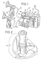
- FIG. 1 illustrates, generally, the usage of one embodiment of the present invention within a breast pump assembly.
- a breast pump assembly 20 is shown in FIG. 1 , and includes two milking units 22 and a motor drive unit 24.
- Each milking unit 22 includes a breast shield 26 and a container 28, such as a bottle, for collecting and storing the breast milk, which is connected to the lower portion of the breast shield 26.
- the milking units 22 are adapted to be used with a piston pump 30.
- a piston cylinder 32 of the piston pump 30 is connectable to the breast shield 26 to operate the milking unit 22 in a manually driven mode (i.e., the piston pump is reciprocated by hand).
- the piston cylinder 32 can be connected to the breast shield 2 6 directly, or by way of tubes 44 which can be attached to a tube attaching means (not shown) on the breast shield 26. Details of this type of breast pump assembly and the piston pump can be gleaned from U.S. Pat. Nos. 4,929,229 and 4,857,051 .
- the motor drive unit 24 is also adapted to receive and hold and to mechanically operate the piston pump 30.
- the motor drive unit 24 is substantially as shown and described in U.S. Pat. No. 5,007,899 .
- An improved cylinder holder, or adapter 34 of the present invention is attachable to the casing 36 of the motor drive unit 24.
- the piston cylinder 32 is received in the adapter 34.
- a piston 33 having a piston rod 38 extending therefrom, is slidably disposed within the piston cylinder 32 and the piston rod 38 is releasably held at one end of an arm 40.
- Arm 40 is mounted at its other end to the casing 36 of the motor drive unit 24 for reciprocal movement of the piston rod 38.
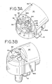
- the adapter 34 includes female coupling components 42 (See FIG. 3A and 3B ) for removably connecting tubes 44 to the breast shields 26 of the respective milking units 22, via male coupling components 50 (See FIG. 2 ).
- the motor drive unit 24 reciprocally moves the piston rod 38, thus moving the piston 33 back and forth within the piston cylinder 32.
- a rearward stroke of the piston rod 38 and thereby piston 33 that is, such that the piston 33 is moved to a position where it is partially exposed from the cylinder 32, generates a pressure change (usually a negative pressure) that is transmitted through the adapter 34 and the tubes 44 to one or both of the milking units 22.
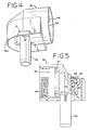
- the adapter 34 of the present invention includes a cap portion 46 that is match-threaded at 48 for substantially airtight attachment to the piston cylinder 32.
- FIG. 5 shows that the inside of the cap portion 46 of one embodiment of the invention includes a seal ring 47 disposed therein for sealing engagement with the piston cylinder 32.
- the cap portion 46 defines in part, a vacuum chamber 52 that communicates with the interior of the piston cylinder 32 and, through ports 54 with the interior of the female coupling components 42.
- the adapter 34 includes a post 56 that is removably received within a post hole (not shown) in the casing 36 to mount the adapter 34 to the motor drive unit 24.
- FIGS. 3A, 3B , and 4 show that the exterior sidewall 46A of the cap portion 46 includes a flange 51. The flange 51 slides into an enlarged slot (also not shown) when the post 56 is inserted in the post hole and the adapter 34 rotated into place (in a similar manner as described in the '899 patent).
- Other means for mounting the adapter to the casing can be readily employed, of course.
- adapter 34 generally includes female coupling components 42.
- the female coupling components 42 are sized and shaped to snugly receive mating male coupling components 50 (discussed in further detail below and shown in FIGS. 8-13 ), which are removably or fixedly attached to the ends of the tubes 44.
- This arrangement serves to provide an easily manipulated secure connection of the tubes 44 to the ports 54 in the female coupling components 42.
- discussion will center on a single female coupling component 42, but it is understood that the coupling components 42 contain identical elements.
- the female coupling component 42 includes an upper surface 68, a lower surface 70, a bottom surface 72, and a rim surface 74.
- the upper surface 68 is sized and shaped to define an upper well 66 therein ( FIG. 5 ).
- the lower surface 70 is sized and shaped to define a lower well 67 therein ( FIG. 5 ).
- the lower surface 70 has a port 54 therein, through which air, or any fluid, can pass from the lower well 67 to the vacuum chamber 52, or vice versa.
- a channel 76 is formed in the lower surface 70 and is in communication with the port 54.
- the upper well 66 has a diameter D1.
- the lower well 67 has a diameter D2.
- Diameter D1 is greater than diameter D2.
- the upper well 66 is connected to the lower well 67 by the rim surface 74.
- the channel 76 extends from an opening 78 in the rim surface 74 to the bottom surface 72 and is open to the lower well 67 at one or more points along the lower surface 70.
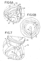
- FIGS. 6A and 6B illustrate overhead detailed schematics of two embodiments of a female coupling component 42.
- the bottom surface 72 of the lower well 67 has at least one radially extending groove 80 formed therein.
- the groove 80 is in fluid communication with the channel 76 formed in the lower surface 70 and is open to the lower well 67 at one or more points along the bottom surface 72.
- the upper well 66 is sized and shaped to receive and thereby provide a snug fit with the male coupling component 50.
- the upper well 66 comprises a generally polygonal or slightly rounded triangular shape. It is understood however, that the upper well 66 can be of any shape provided it is sized to match a sealing portion 88 of a male coupling component 50 as will be described in further detail hereinafter.
- adapter 34 also includes a stopper mount 58A, 588 and a stopper rest 60. Additionally, the stopper mount 58A further includes an aperture surface 62A, 62B that defines an aperture 64. As shown in FIG. 3A , the aperture surface 62A may extend outward from the adapter 34 such that stopper mount 58A is sized and shaped as an elevated cylinder. Alternatively, as shown in FIG. 3B , aperture surface 62B may extend inward into the adapter 34 such that stopper mount 58B is a well within the adapter 34. Stopper mount 58A, 58B receives a mounting end 98A, 98B of stopper 96A , 96B (see FIGS. 14A, 14B, 14C and 14D ) thereon, to mount the stopper 96A, 96B on the adapter 34.
- the stopper 96A, 96B is shown generally in FIGS. 14A, 14B, 14C and 14D .
- Plug 100A, 100B of stopper 96A, 96B may be placed, when not in use as a stopper, in the stopper rest 60.
- stopper 96A, 96B is used to "cut off' one of multiple female coupling components 42 in the event that the user wishes to only utilize one of the milking units 22.
- stopper 96A, 96B may include gripping ridges 102 on a top surface 101 as depicted in FIG. 14C .
- a predetermined amount of leakage may be provided by orifice 104 ( FIG. 14C ) or in the alternate, an outer aperture or groove 106 ( FIG. 14D ). It will be understood that the orifice 104, or in the alternate groove or aperture 106 , functions to permit fluid (air) venting between atmosphere and the interior of the female portion 42.
- plug 100B may be any suitable complementary shape with wall 68, and is preferably the depicted polygonal shape including gently convex outer walls.
- stopper rest 60 is similar in shape and size, to the wall 68 of upper well 66.
- the purpose for this is that the plug 100A, 100B of the stopper 96A, 96B is shaped similarly to a sealing portion 88 (see FIG. 8 ) to snugly fit into the stopper rest 60 (when not is use), and the upper well 66 of the female coupling component 42 (when in use).
- tubes 44 are attached to male coupling components 50, which in turn may be inserted into corresponding female coupling components 42. This arrangement serves to provide an easily manipulatable and secure connection of tubes 44, via male coupling components 50, to adapter 34.
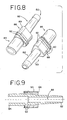
- FIGS. 8-9 illustrate various perspectives of one embodiment of a male coupling component 50.
- male coupling component 50 is shown with a first end 82 to which a tube 44 is attached, and a second end 84.
- a passageway 86 extends through the male coupling component 50 between the first end 82 and the second end 84 for conveying the fluid pressure.
- the connector 50 includes a radially outwardly extending sealing portion 88 formed on the male coupling component 50 between the first end 82 and the second end 84 and spaced from the second end 84.
- the sealing portion 88 can be of a generally polygonal or slightly rounded triangular shape.
- the sealing portion 88 can be of any shape, so long as it matches the shape of the upper well 66 of the female coupling component 42.
- the sealing portion 88 also has a sealing surface 90 that includes at least one circumferential sealing ring 92 thereon, which engages the upper surface 68 of the upper well 66 to form a substantially airtight seal such that ambient air is prevented from entering the female coupling component 42.
- the upper surface 68 may include at least one circumferential groove (not shown) therein that engages with the circumferential sealing ring 92 to form the substantially airtight seal.
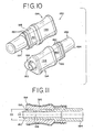
- FIGS. 10-11 illustrate various perspectives of another embodiment of a male coupling component 150.
- male coupling component 150 is shown with a first end 182 to which a vacuum tube 44 is attached, and a second end 184.
- a gripping portion 194 surrounds the first end 182.
- FIGS. 10 & 11 show that the gripping portion 194 has a slightly concaved exterior surface 196 and a cylindrical interior surface 198 with a diameter D3 greater than diameter D4 of the first end 182 such that a tube 44 can be attached to the first end 182, yet snugly received within the interior surface 198 of the gripping portion 194.
- a passageway 186 extends through the male coupling component 150 between the first end 182 and the second end 184 for conveying the fluid pressure.
- the male coupling component 150 includes a radially outwardly extending sealing portion 188 formed on the male coupling component 150 between the first end 182 and the second end 184, spaced from the second end 184.
- the sealing portion 188 can be of any shape so long as it is sized and shaped to match the size and shape of the upper well 66 of the female coupling component 42, but is depicted as having a generally polygonal or slightly rounded triangular shape.
- the sealing portion 188 has a sealing surface 190 that includes at least one circumferential sealing ring 192 thereon, which engages the upper surface 68 of the upper well 66 to form a substantially airtight seal such that ambient air is prevented from entering the female coupling component 42.
- the upper surface 68 may include at least one circumferential groove (not shown) therein that engages with the circumferential sealing ring 192 to form the substantially airtight seal.
- FIGS. 12-13 illustrate various perspectives of yet another embodiment of a male coupling component 250.
- male coupling component 250 is shown with a first end 282 to which a tube 44 is attached, and a second end 284.
- a passageway 286 extends through the male coupling component 250 between the first end 282 and the second end 284 for conveying the fluid pressure.
- the connector 250 includes a radially outwardly extending sealing portion 288 formed on the male coupling component 250 between the first end 282 and the second end 284, spaced from the second end 284.
- the sealing portion 288 can be of any shape, so long as it is sized and shaped to match the size and shape of the upper well 66 of the female coupling component 42, but is depicted as having a generally circular shape.
- the sealing portion 288 has a sealing surface 290 that engages the upper surface 68 of the upper well 66 to form a substantially airtight seal such that ambient air is prevented from entering the coupling component 42.
- the present invention provides for a unique fit between the male coupling components 50 and the female coupling components 42. This unique design assures that only this coupling component and connector will be successfully mated, thereby assuring that only properly matched equipment will be used.
Landscapes
- Health & Medical Sciences (AREA)
- Heart & Thoracic Surgery (AREA)
- Biomedical Technology (AREA)
- Vascular Medicine (AREA)
- Engineering & Computer Science (AREA)
- Anesthesiology (AREA)
- Pediatric Medicine (AREA)
- Hematology (AREA)
- Life Sciences & Earth Sciences (AREA)
- Animal Behavior & Ethology (AREA)
- General Health & Medical Sciences (AREA)
- Public Health (AREA)
- Veterinary Medicine (AREA)
- External Artificial Organs (AREA)
- Quick-Acting Or Multi-Walled Pipe Joints (AREA)
Claims (38)
- Adapter (34) zum Verbinden einer Vakuumquelle (30) mit einer Brusthaube (26) mit Schlauchmaterial (44) aufweisend: ein Gehäuse (46), welches an die Vakuumquelle (30) anschliessbar ist und eine innere Kammer (52) umfasst, die in mit der Vakuumquelle (30) kommuniziert;
eine oder mehrere weibliche Kopplungskomponenten (42), wobei jede dieser einen oder mehreren weiblichen Kopplungskomponenten (42) durch eine innere Seitenwandoberfläche (68) des Gehäuses (46) definiert ist, wobei die innere Seitenwandoberfläche einen oberen Bereich (66) umfasst mit einem ersten Seitenwanddurchmesser (D1) und einen unteren Bereich (67) umfasst mit einem zweiten Seitenwanddurchmesser (D2) sowie einen Randbereich (74) zwischen diesem oberen Bereich (66) und diesem unteren Bereich (67) umfasst, der den oberen Bereich (66) und den unteren Bereich (67) miteinander verbindet, wobei der zweite Seitenwanddurchmesser (D2) kleiner als der erste Seitenwanddurchmesser (D1) ist, wobei der untere Bereich (67) einen oder mehrere darin ausgestaltete Anschlüsse (54) umfasst, welche eine Kommunikation der weiblichen Kopplungskomponente (42) mit der inneren Kammer (52) ermöglichen, sowie einen oder mehrere darin ausgestaltete Kanäle (76) umfasst, welche mit einer Öffnung (78) im Randbereich (74) kommunizieren, und
einen oder mehrere männliche Kopplungskomponenten (50), wobei jede dieser einen oder mehreren männlichen Kopplungskomponenten (50) ein erstes Ende (62), ein zweites Ende (84) und einen Durchgang (86), welcher sich zwischen dem ersten Ende (82) und dem zweiten Ende (84) erstreckt, umfasst, wobei das erste Ende (82) derart bemessen und geformt ist, dass es am Schlauchmaterial (44) anschliessbar ist, wobei das zweite Ende (84) bemessen und geformt ist, um in dem einen oder den mehreren weiblichen Kopplungskomponenten (42) aufgenommen zu werden, und einen ersten Enddurchmesser aufweist, wobei jede der einen oder der mehreren männlichen Kopplungskomponenten (50) ausserdem einen Abdichtbereich (88) zwischen dem ersten Ende (82) und dem zweiten Ende (84) umfasst, wobei dieser Abdichtbereich (88) eine um die Peripherie herum ausgestaltete Dichtfläche (90) aufweist, wobei dieser Abdichtbereich (88) einen zweiten Enddurchmesser aufweist, der grösser ist als der erste Enddurchmesser, wobei der Abdichtbereich (88) bemessen und geformt ist, um im oberen Bereich (66) der weiblichen Kopplungskomponente (42) derart aufgenommen zu werden, dass die Verbindungsdichtfläche (90) im Wesentlichen in einer luftdichten Verbindung mit der inneren Seitenwandoberfläche (68) steht. - Adapter gemäss Anspruch 1, wobei der Kanal (76) axial entlang dem unteren Bereich (67) ausgebildet ist.
- Adapter gemäss Anspruch 1, wobei die eine oder die mehreren weiblichen Kopplungskomponenten (42) ausserdem durch eine Bodenoberfläche (72) des Gehäuses (36) definiert sind.
- Adapter gemäss Anspruch 3, wobei die Bodenoberfläche (72) eine oder mehrere darin ausgebildete Nuten (80) umfasst, welche mit dem einen oder den mehreren Kanälen (76) kommunizieren.
- Adapter gemäss Anspruch 3, wobei der untere Bereich (67) drei von den einen oder mehreren Kanälen (76) umfasst, welche axial im unteren Bereich (67) der inneren Seitenwandoberfläche (78) ausgebildet sind, wobei die drei Kanäle (76) in gleichmässigen Abständen um die Peripherie des unteren Bereiches (67) der inneren Oberfläche (68) herum angeordnet sind, und wobei die Bodenoberfläche (72) drei radial darin ausgebildete Nuten (80) umfasst, welche in der Bodenoberfläche (72) in entsprechender Kommunikation mit dem einen oder den mehreren Kanälen (76) im unteren Bereich (67) der inneren Seitenwandoberfläche (68) stehen.
- Adapter gemäss Anspruch 1, wobei zwei der einen oder der mehreren weiblichen Kopplungskomponenten (42) an diesem vorgesehen sind, und zwei der einen oder der mehreren männlichen Kopplungskomponenten (50) vorgesehen sind, um in den weiblichen Kopplungskomponenten (42) aufgenommen zu werden, und wobei ausserdem ein Stopper (96A, 96B) vorhanden ist, welcher bemessen und geformt ist, um den oberen Bereich (66) von einer der zwei weiblichen Kopplungskomponenten (42) dichtend zu verbinden.
- Adapter gemäss Anspruch 6, wobei der Stopper (96A, 96B) ein Loch (104, 106) umfasst, welches derart darin ausgebildet ist, dass sich das Loch (104, 106) zwischen Umgebungsatmosphäre und der weiblichen Kopplungskomponente (42) erstreckt, wenn der Stopper (96A, 96B) mit der weiblichen Kopplungskomponente (42) verbunden ist.
- Adapter gemäss Anspruch 7, wobei das Loch (104, 106) entlang einer Aussenwand eines Stopfenbereiches des Stoppers (96A, 96B) ausgebildet ist.
- Adapter gemäss Anspruch 7, wobei das Loch (104, 106) durch den Stopper (96A, 96B) hindurch ausgebildet ist, um einen Luftdurchlass zwischen Umgebungsatmosphäre und der weiblichen Kopplungskomponente (42) zu erlauben, wenn der Stopper (96A, 96B) mit dieser verbunden ist.
- Adapter gemäss Anspruch 1, wobei der obere Bereich einen hauptsächlich kreisförmigen, axialen Querschnitt umfasst.
- Adapter gemäss Anspruch 10, wobei der Abdichtbereich (88) einen hauptsächlich kreisförmigen, axialen Querschnitt aufweist, welcher derart bemessen und geformt ist, dass er dem Querschnitt des oberen Bereiches (66) entspricht.
- Adapter gemäss Anspruch 1, wobei der obere Bereich (66) einen hauptsächlich polygonalen, axialen Querschnitt umfasst.
- Adapter gemäss Anspruch 11, wobei der Abdichtbereich (88) einen hauptsächlich polygonalen, axialen Querschnitt umfasst, welcher derart bemessen und geformt ist, dass er dem Querschnitt des oberen Bereiches (66) entspricht.
- Adapter gemäss Anspruch 1, wobei der obere Bereich (66) einen hauptsächlich dreieckigen, axialen Querschnitt umfasst, wobei der obere Bereich (66) drei gebogene Seiten aufweist.
- Adapter gemäss Anspruch 14, wobei der Abdichtbereich (88) einen hauptsächlich dreieckigen, axialen Querschnitt umfasst, wobei der Abdichtbereich (88) drei gebogene Seiten umfasst, und wobei der Abdichtbereich (88) derart bemessen und geformt ist, dass er dem Querschnitt des oberen Bereiches (66) entspricht.
- Adapter gemäss Anspruch 1, wobei der Abdichtbereich (88) zumindest einen umlaufenden Ring (92) umfasst, welcher einstückig daran ausgeformt ist.
- Adapter gemäss Anspruch 16, wobei der obere Bereich (66) zumindest eine umlaufende, darin ausgebildete Nut umfasst, und wobei der umlaufende Ring (92) bemessen und geformt ist, um dichtend mit der umlaufenden Nut verbunden zu sein, wenn der Abdichtbereich (88) im oberen Bereich (66) aufgenommen ist.
- Adapter gemäss Anspruch 1, wobei die Vakuumquelle eine Kolbenpumpe (30) ist mit einem Kolbenzylinder (32), und einem Kolben (33), welcher im Kolbenzylinder (32) angeordnet ist, wobei der Adapter (34) als ein Zylinderhalter ausgestaltet ist, welcher an einem Ausgangsende des Kolbenzylinders (32) aufgenommen ist, wobei die Kolbenpumpe (30) mittels Hinundherbewegung des Kolbens (33) im Inneren des Kolbenzylinders (32) ein intermittierendes Vakuum generiert, und wobei der Kolbenzylinder (32) ein Ende aufweist, durch welches sich der Kolben (33) bei Gebrauch hindurch erstreckt.
- Adapter gemäss Anspruch 1, wobei das zweite Ende (84) der männlichen Kopplungskomponente (50) bemessen und geformt ist, um im unteren Bereich (67) und in der Brusthaube (26) aufgenommen zu werden.
- Adapter gemäss Anspruch 1 zum Verbinden der Vakuumquelle (30) mit der Brusthaube (26), wobei ein intermittierendes Vakuum dabei in der Brusthaube (26) generiert wird, um Milch aus einer Brust zu exprimieren, wobei der Abdichtbereich (88) zumindest einen umlaufenden Ring (92) aufweist, welcher einstückig daran ausgeformt ist, und wobei der Adapter (34) einen Stopper (96A, 96B) aufweist, welcher bemessen und geformt ist, um im oberen Bereich (66) der weiblichen Kopplungskomponente (42) aufgenommen zu werden, so dass der Stopper (96A, 96B) in einer im Wesentlichen luftdichten Verbindung mit der inneren Seitenwandoberfläche (68) steht.
- Adapter gemäss Anspruch 20, wobei zwei weibliche Kopplungskomponenten (42) an diesem vorgesehen sind, um eine entsprechende männliche Kopplungskomponente (50) aufzunehmen, wobei ausserdem der Stopper (96A, 96B) vorhanden ist, welcher bemessen und geformt ist, um den oberen Bereich von einer der zwei weiblichen Kopplungskomponenten (42) dichtend zu verbinden,
wobei der Stopper (96A, 96B) ein Loch (104, 106) umfasst, welches darin derart ausgestaltet ist, dass sich das Loch (104, 106) zwischen Umgebungsatmosphäre und der weiblichen Kopplungskomponente (42) erstreckt, wenn der Stopper (96A, 96B) mit der weiblichen Kopplungskomponente (42) verbunden ist, und
wobei das Loch (104, 106) dazu ausgebildet ist, einen Vakuumdruck zu regulieren, wenn nur eine einzige Kopplungskomponente in Gebrauch ist, so dass das generierte Vakuum für einen gegebenen Kolbenhub im Wesentlichen dasselbe ist, unabhängig davon, ob eine oder zwei Kopplungskomponenten benutzt werden. - Brustpumpenvorrichtung mit einem Adapter gemäss einem der Ansprüche 1 bis 21, wobei die Vorrichtung ausserdem eine Vakuumquelle (30) aufweist, einen Schlauch (44) und eine oder mehrere Milcheinheiten (22), welche eine Brusthaube (26) umfassen, die zur Aufnahme der Brust einer Mutter zum Exprimieren von Milch geeignet ist, einen Behälter (28) für exprimierte Milch, welcher in Fluidkommunikation mit der Brusthaube (26) steht, und ein Schlauchanschlussmittel, welches in Kommunikation mit der Brusthaube (26) steht, um den Schlauch (44) daran zu anzuschliessen,.
- Brustpumpenvorrichtung gemäss Anspruch 22, wobei der Kanal (76) axial entlang dem unteren Bereich (67) ausgestaltet ist.
- Brustpumpenvorrichtung gemäss Anspruch 22, wobei eine oder mehrere weibliche Kopplungskomponenten (42) ausserdem durch eine Bodenoberfläche (72) des Gehäuses (36) definiert sind.
- Brustpumpenvorrichtung gemäss Anspruch 24, wobei die Bodenoberfläche (72) eine oder mehrere radial darin ausgestaltete Nuten (80) umfasst, welche mit dem einen oder den mehreren Kanälen (76) kommunizieren.
- Brustpumpenvorrichtung gemäss Anspruch 25, wobei der untere Bereich (67) drei Kanäle (76) umfasst, welche axial im unteren Bereich (67) der inneren Seitenwandoberfläche (68) ausgestaltet sind, wobei die Kanäle (76) in gleichmässigen Abständen um die Peripherie des unteren Bereiches (67) der inneren Seitenwandoberfläche (68) herum angeordnet sind, und wobei die Bodenoberfläche (72) drei radial darin ausgestaltete Nuten (80) umfasst, welche in entsprechender Kommunikation mit den Kanälen (76) im unteren Bereich (67) der inneren Seitenwandoberfläche (68) stehen.
- Brustpumpenvorrichtung gemäss Anspruch 22, wobei zwei weibliche Kopplungskomponenten (42) am Adapter (34) vorgesehen sind, und wobei zwei männliche Kopplungskomponenten (50) vorgesehen sind, um in den weiblichen Kopplungskomponenten (42) aufgenommen zu werden, und ausserdem aufweisend ein Stopper (96A, 96B), welcher derart bemessen und geformt ist, dass er den oberen Bereich (66) von einer der zwei Kopplungskomponenten (42) dichtend verbindet.
- Brustpumpenvorrichtung gemäss Anspruch 27, wobei der Stopper (96A, 96B) ein Loch (104, 106) aufweist, welches derart darin ausgestaltet ist, dass sich das Loch (104, 106) zwischen Umgebungsatmosphäre und der weiblichen Kopplungskomponente (42) erstreckt, wenn der Stopper (96A, 96B) mit der weiblichen Kopplungskomponente (42) verbunden ist, wobei das Loch (104, 106) dazu ausgebildet ist, einen Vakuumdruck zu regulieren, wenn nur eine einzige Kopplungskomponente in Gebrauch ist, so dass das generierte Vakuum für einen gegebenen Kolbenhub im Wesentlichen dasselbe ist, unabhängig davon, ob eine oder beide der Kopplungskomponenten benutzt werden.
- Brustpumpenvorrichtung gemäss Anspruch 22, wobei der obere Bereich (66) einen im Wesentlichen kreisförmigen, axialen Querschnitt umfasst.
- Brustpumpenvorrichtung gemäss Anspruch 29, wobei der Abdichtbereich (88) einen im Wesentlichen kreisförmigen, axialen Querschnitt umfasst, welcher derart bemessen und geformt ist, dass er dem Querschnitt des oberen Bereiches (66) entspricht.
- Brustpumpenvorrichtung gemäss Anspruch 22, wobei der obere Bereich (66) einen im Wesentlichen polygonalen, axialen Querschnitt umfasst.
- Brustpumpenvorrichtung gemäss Anspruch 31, wobei der Abdichtbereich (88) einen im Wesentlichen polygonalen, axialen Querschnitt umfasst, welcher derart bemessen und geformt ist, dass er dem Querschnitt des oberen Bereiches (66) entspricht.
- Brustpumpenvorrichtung gemäss Anspruch 22, wobei der obere Bereich (66) einen im Wesentlichen dreieckigen, axialen Querschnitt umfasst, und wobei der obere Bereich drei gebogene Seiten aufweist.
- Brustpumpenvorrichtung gemäss Anspruch 33, wobei der Abdichtbereich (88) einen im Wesentlichen dreieckigen, axialen Querschnitt umfasst und drei gebogene Seiten aufweist, und wobei der Abdichtbereich derart bemessen und geformt ist, dass der dem Querschnitt des oberen Bereiches (66) entspricht.
- Brustpumpenvorrichtung gemäss Anspruch 22, wobei der Abdichtbereich (88) zumindest einen umlaufenden Ring (92) umfasst, welcher einstückig daran angeformt ist.
- Brustpumpenvorrichtung gemäss Anspruch 35, wobei der obere Bereich (66) zumindest eine umlaufende Nut umfasst, und wobei der umlaufende Ring (92) derart bemessen und geformt ist, dass er eine dichtende Verbindung mit der umlaufenden Nut eingeht, wenn der Abdichtbereich im oberen Bereich aufgenommen ist.
- Brustpumpenvorrichtung gemäss Anspruch 22, wobei die Quelle des intermittierenden Vakuums eine Kolbenpumpe (30) ist, welche einen Kolbenzylinder (32) und einen Kolben (33) aufweist, wobei der Kolben (33) im Kolbenzylinder (32) angeordnet ist, wobei der Adapter (34) als ein Zylinderhalter bemessen und geformt ist, welcher in einem Ausgangsende des Kolbenzylinders (32) aufgenommen ist, wobei die Kolbenpumpe (30) mittels Hinundherbewegung des Kolbens (33) im Inneren des Kolbenzylinders (32) ein intermittierendes Vakuum generiert, und wobei der Kolbenzylinder (32) ein Ende aufweist, durch welches sich der Kolben (33) bei Gebrauch hindurch erstreckt.
- Brustpumpenvorrichtung gemäss Anspruch 22, wobei das zweite Ende (84) der männlichen Kopplungskomponente (50) bemessen und geformt ist, um im unteren Bereich (67) und am Schlauchanschlussmittel aufgenommen zu werden.
Priority Applications (2)
| Application Number | Priority Date | Filing Date | Title |
|---|---|---|---|
| EP10010245A EP2263711A1 (de) | 2002-07-19 | 2003-07-18 | Steck- und Buchsenkopplungselement |
| EP10191900A EP2335750A1 (de) | 2002-07-19 | 2003-07-18 | Steckervorrichtung |
Applications Claiming Priority (7)
| Application Number | Priority Date | Filing Date | Title |
|---|---|---|---|
| US39743902P | 2002-07-19 | 2002-07-19 | |
| US397439P | 2002-07-19 | ||
| US600078 | 2003-06-20 | ||
| US10/600,078 US7357782B2 (en) | 2002-07-19 | 2003-06-20 | Connector device |
| PCT/US2003/022408 WO2004009151A2 (en) | 2002-07-19 | 2003-07-18 | Breast pump connector device |
| US10/622,720 US7326184B2 (en) | 2002-07-19 | 2003-07-18 | Connector device |
| US622720 | 2003-07-18 |
Related Child Applications (2)
| Application Number | Title | Priority Date | Filing Date |
|---|---|---|---|
| EP10010245.8 Division-Into | 2010-09-23 | ||
| EP10191900.9 Division-Into | 2010-11-19 |
Publications (3)
| Publication Number | Publication Date |
|---|---|
| EP1523348A2 EP1523348A2 (de) | 2005-04-20 |
| EP1523348A4 EP1523348A4 (de) | 2008-03-26 |
| EP1523348B1 true EP1523348B1 (de) | 2011-03-30 |
Family
ID=30773519
Family Applications (1)
| Application Number | Title | Priority Date | Filing Date |
|---|---|---|---|
| EP03765689A Expired - Lifetime EP1523348B1 (de) | 2002-07-19 | 2003-07-18 | Verbindungsvorrichtung |
Country Status (9)
| Country | Link |
|---|---|
| US (1) | US7326184B2 (de) |
| EP (1) | EP1523348B1 (de) |
| JP (1) | JP4484702B2 (de) |
| KR (1) | KR100977463B1 (de) |
| CN (1) | CN100457201C (de) |
| AU (1) | AU2003256602C1 (de) |
| CA (1) | CA2492792C (de) |
| NO (1) | NO20050443L (de) |
| WO (1) | WO2004009151A2 (de) |
Families Citing this family (11)
| Publication number | Priority date | Publication date | Assignee | Title |
|---|---|---|---|---|
| US6749582B2 (en) | 2002-04-30 | 2004-06-15 | The First Years Inc. | Pumping breast milk |
| US7780201B2 (en) * | 2006-10-13 | 2010-08-24 | Medela Holding Ag | Tube connector with three part construction and latching component |
| WO2010083485A2 (en) | 2009-01-16 | 2010-07-22 | Learning Curve Brands, Inc. | Breast pump and method of use |
| US9290758B2 (en) * | 2009-06-12 | 2016-03-22 | Roche Innovation Center Copenhagen A/S | Potent anti APOB antisense compounds |
| GB2496650A (en) * | 2011-11-17 | 2013-05-22 | Mothercare Uk Ltd | Breast pump with angularly adjustable funnel |
| US10039912B2 (en) | 2012-07-10 | 2018-08-07 | St. Jude Medical, Atrial Fibrillation Division, Inc. | System and method for coupling a tube with a medical device handle |
| EP2897667B1 (de) * | 2012-09-24 | 2016-05-25 | Koninklijke Philips N.V. | Milchpumpe |
| CN203577015U (zh) | 2012-09-24 | 2014-05-07 | 皇家飞利浦有限公司 | 吸乳泵系统 |
| US9248221B2 (en) | 2014-04-08 | 2016-02-02 | Incuvate, Llc | Aspiration monitoring system and method |
| US10226263B2 (en) | 2015-12-23 | 2019-03-12 | Incuvate, Llc | Aspiration monitoring system and method |
| GB202117909D0 (en) * | 2021-12-10 | 2022-01-26 | Mayborn Uk Ltd | Connector and method of securing a tube |
Family Cites Families (14)
| Publication number | Priority date | Publication date | Assignee | Title |
|---|---|---|---|---|
| US4857051A (en) | 1980-09-05 | 1989-08-15 | Isg/Ag | Breastpump |
| US4569344A (en) * | 1984-07-23 | 1986-02-11 | Ballard Medical Products | Aspirating/ventilating apparatus and method |
| JPS6294170A (ja) * | 1985-10-21 | 1987-04-30 | ピジヨン株式会社 | 搾乳器 |
| US5007899A (en) * | 1988-02-29 | 1991-04-16 | Isg/Ag | Drive unit adapted for use with manual piston pump |
| US4929229A (en) | 1988-11-30 | 1990-05-29 | Isg/Ag | Breastpump having improved valve mechanism |
| CA2046525A1 (en) * | 1990-07-10 | 1992-01-11 | Karl O. A. H. Larsson | Breast pump with massage for improved lactation |
| US5569222A (en) * | 1994-06-21 | 1996-10-29 | Clintec Nutrition Company | Adapter for a variety of tubes having various diameters and a method of using the adapter |
| US5601531A (en) * | 1995-02-16 | 1997-02-11 | Medela, Incorporated | Breast pump assembly and method of using same |
| US6257847B1 (en) * | 1995-08-03 | 2001-07-10 | Medela, Inc. | Diaphragm pump and pump for double-breast pumping |
| US5720722A (en) * | 1996-01-11 | 1998-02-24 | Medela, Incorporated | Connector for use in single and double breast pumping and breast pump using same |
| DE59610174D1 (de) * | 1996-04-14 | 2003-04-03 | Medela Ag Baar | Einrichtung zum Absaugen von Muttermilch |
| US6139521A (en) * | 1996-06-03 | 2000-10-31 | Medela Holding Ag | Breastpump having particular application as a small motorized pump capable of double-breast pumping |
| KR100371618B1 (ko) | 2000-04-19 | 2003-02-11 | 서경득 | 유축기 |
| US6706012B2 (en) * | 2000-06-12 | 2004-03-16 | L. Jason Clute | Apparatus for expressing milk |
-
2003
- 2003-07-18 KR KR1020057000998A patent/KR100977463B1/ko not_active Expired - Fee Related
- 2003-07-18 CN CNB038172682A patent/CN100457201C/zh not_active Expired - Fee Related
- 2003-07-18 CA CA2492792A patent/CA2492792C/en not_active Expired - Fee Related
- 2003-07-18 JP JP2004523533A patent/JP4484702B2/ja not_active Expired - Fee Related
- 2003-07-18 WO PCT/US2003/022408 patent/WO2004009151A2/en not_active Ceased
- 2003-07-18 US US10/622,720 patent/US7326184B2/en not_active Expired - Lifetime
- 2003-07-18 AU AU2003256602A patent/AU2003256602C1/en not_active Ceased
- 2003-07-18 EP EP03765689A patent/EP1523348B1/de not_active Expired - Lifetime
-
2005
- 2005-01-26 NO NO20050443A patent/NO20050443L/no not_active Application Discontinuation
Also Published As
| Publication number | Publication date |
|---|---|
| WO2004009151A2 (en) | 2004-01-29 |
| WO2004009151A3 (en) | 2004-09-23 |
| AU2003256602C1 (en) | 2009-05-21 |
| EP1523348A2 (de) | 2005-04-20 |
| EP1523348A4 (de) | 2008-03-26 |
| CA2492792C (en) | 2011-10-04 |
| AU2003256602A1 (en) | 2004-02-09 |
| JP4484702B2 (ja) | 2010-06-16 |
| KR100977463B1 (ko) | 2010-08-23 |
| US7326184B2 (en) | 2008-02-05 |
| CN1668348A (zh) | 2005-09-14 |
| KR20050061441A (ko) | 2005-06-22 |
| NO20050443L (no) | 2005-04-15 |
| JP2005533575A (ja) | 2005-11-10 |
| CN100457201C (zh) | 2009-02-04 |
| US20040059307A1 (en) | 2004-03-25 |
| CA2492792A1 (en) | 2004-01-29 |
| AU2003256602B2 (en) | 2008-10-23 |
Similar Documents
| Publication | Publication Date | Title |
|---|---|---|
| US8192396B2 (en) | Connector device | |
| US5797875A (en) | Breast pump assembly and method of using same | |
| US5720722A (en) | Connector for use in single and double breast pumping and breast pump using same | |
| AU2007313399B2 (en) | Tube connector | |
| EP1523348B1 (de) | Verbindungsvorrichtung | |
| AU2010300011B2 (en) | Breast shield for expressing human breast milk | |
| KR100371618B1 (ko) | 유축기 | |
| US20200384172A1 (en) | Smart wearable breast pumping machine and nipple correction and breast enhancement machine | |
| KR102007473B1 (ko) | 스마트 웨어러블 유축기 | |
| HK1150790A (en) | Male and female coupling component | |
| HK1155680A (en) | Connector device | |
| CN219896578U (zh) | 吸奶器 | |
| KR200447947Y1 (ko) | 모유착유기용 어댑터 |
Legal Events
| Date | Code | Title | Description |
|---|---|---|---|
| PUAI | Public reference made under article 153(3) epc to a published international application that has entered the european phase |
Free format text: ORIGINAL CODE: 0009012 |
|
| 17P | Request for examination filed |
Effective date: 20050119 |
|
| AK | Designated contracting states |
Kind code of ref document: A2 Designated state(s): AT BE BG CH CY CZ DE DK EE ES FI FR GB GR HU IE IT LI LU MC NL PT RO SE SI SK TR |
|
| AX | Request for extension of the european patent |
Extension state: AL LT LV MK |
|
| RIC1 | Information provided on ipc code assigned before grant |
Ipc: 7A 61M 1/06 A |
|
| DAX | Request for extension of the european patent (deleted) | ||
| A4 | Supplementary search report drawn up and despatched |
Effective date: 20080226 |
|
| 17Q | First examination report despatched |
Effective date: 20081120 |
|
| GRAP | Despatch of communication of intention to grant a patent |
Free format text: ORIGINAL CODE: EPIDOSNIGR1 |
|
| GRAS | Grant fee paid |
Free format text: ORIGINAL CODE: EPIDOSNIGR3 |
|
| GRAA | (expected) grant |
Free format text: ORIGINAL CODE: 0009210 |
|
| AK | Designated contracting states |
Kind code of ref document: B1 Designated state(s): AT BE BG CH CY CZ DE DK EE ES FI FR GB GR HU IE IT LI LU MC NL PT RO SE SI SK TR |
|
| REG | Reference to a national code |
Ref country code: GB Ref legal event code: FG4D |
|
| REG | Reference to a national code |
Ref country code: CH Ref legal event code: EP |
|
| REG | Reference to a national code |
Ref country code: IE Ref legal event code: FG4D |
|
| REG | Reference to a national code |
Ref country code: CH Ref legal event code: NV Representative=s name: ISLER & PEDRAZZINI AG |
|
| REF | Corresponds to: |
Ref document number: 60336562 Country of ref document: DE Date of ref document: 20110512 Kind code of ref document: P |
|
| REG | Reference to a national code |
Ref country code: DE Ref legal event code: R096 Ref document number: 60336562 Country of ref document: DE Effective date: 20110512 |
|
| REG | Reference to a national code |
Ref country code: SE Ref legal event code: TRGR |
|
| REG | Reference to a national code |
Ref country code: NL Ref legal event code: T3 |
|
| REG | Reference to a national code |
Ref country code: ES Ref legal event code: FG2A Ref document number: 2361153 Country of ref document: ES Kind code of ref document: T3 Effective date: 20110614 |
|
| REG | Reference to a national code |
Ref country code: GR Ref legal event code: EP Ref document number: 20110401171 Country of ref document: GR Effective date: 20110614 |
|
| PG25 | Lapsed in a contracting state [announced via postgrant information from national office to epo] |
Ref country code: CY Free format text: LAPSE BECAUSE OF FAILURE TO SUBMIT A TRANSLATION OF THE DESCRIPTION OR TO PAY THE FEE WITHIN THE PRESCRIBED TIME-LIMIT Effective date: 20110330 Ref country code: AT Free format text: LAPSE BECAUSE OF FAILURE TO SUBMIT A TRANSLATION OF THE DESCRIPTION OR TO PAY THE FEE WITHIN THE PRESCRIBED TIME-LIMIT Effective date: 20110330 Ref country code: FI Free format text: LAPSE BECAUSE OF FAILURE TO SUBMIT A TRANSLATION OF THE DESCRIPTION OR TO PAY THE FEE WITHIN THE PRESCRIBED TIME-LIMIT Effective date: 20110330 Ref country code: SI Free format text: LAPSE BECAUSE OF FAILURE TO SUBMIT A TRANSLATION OF THE DESCRIPTION OR TO PAY THE FEE WITHIN THE PRESCRIBED TIME-LIMIT Effective date: 20110330 |
|
| PG25 | Lapsed in a contracting state [announced via postgrant information from national office to epo] |
Ref country code: BE Free format text: LAPSE BECAUSE OF FAILURE TO SUBMIT A TRANSLATION OF THE DESCRIPTION OR TO PAY THE FEE WITHIN THE PRESCRIBED TIME-LIMIT Effective date: 20110330 |
|
| PG25 | Lapsed in a contracting state [announced via postgrant information from national office to epo] |
Ref country code: PT Free format text: LAPSE BECAUSE OF FAILURE TO SUBMIT A TRANSLATION OF THE DESCRIPTION OR TO PAY THE FEE WITHIN THE PRESCRIBED TIME-LIMIT Effective date: 20110801 Ref country code: EE Free format text: LAPSE BECAUSE OF FAILURE TO SUBMIT A TRANSLATION OF THE DESCRIPTION OR TO PAY THE FEE WITHIN THE PRESCRIBED TIME-LIMIT Effective date: 20110330 |
|
| PGFP | Annual fee paid to national office [announced via postgrant information from national office to epo] |
Ref country code: CH Payment date: 20110725 Year of fee payment: 9 |
|
| PG25 | Lapsed in a contracting state [announced via postgrant information from national office to epo] |
Ref country code: RO Free format text: LAPSE BECAUSE OF FAILURE TO SUBMIT A TRANSLATION OF THE DESCRIPTION OR TO PAY THE FEE WITHIN THE PRESCRIBED TIME-LIMIT Effective date: 20110330 Ref country code: SK Free format text: LAPSE BECAUSE OF FAILURE TO SUBMIT A TRANSLATION OF THE DESCRIPTION OR TO PAY THE FEE WITHIN THE PRESCRIBED TIME-LIMIT Effective date: 20110330 Ref country code: CZ Free format text: LAPSE BECAUSE OF FAILURE TO SUBMIT A TRANSLATION OF THE DESCRIPTION OR TO PAY THE FEE WITHIN THE PRESCRIBED TIME-LIMIT Effective date: 20110330 |
|
| PGFP | Annual fee paid to national office [announced via postgrant information from national office to epo] |
Ref country code: GR Payment date: 20110726 Year of fee payment: 9 Ref country code: SE Payment date: 20110727 Year of fee payment: 9 |
|
| PLBE | No opposition filed within time limit |
Free format text: ORIGINAL CODE: 0009261 |
|
| STAA | Information on the status of an ep patent application or granted ep patent |
Free format text: STATUS: NO OPPOSITION FILED WITHIN TIME LIMIT |
|
| PG25 | Lapsed in a contracting state [announced via postgrant information from national office to epo] |
Ref country code: DK Free format text: LAPSE BECAUSE OF FAILURE TO SUBMIT A TRANSLATION OF THE DESCRIPTION OR TO PAY THE FEE WITHIN THE PRESCRIBED TIME-LIMIT Effective date: 20110330 Ref country code: MC Free format text: LAPSE BECAUSE OF NON-PAYMENT OF DUE FEES Effective date: 20110731 |
|
| 26N | No opposition filed |
Effective date: 20120102 |
|
| REG | Reference to a national code |
Ref country code: IE Ref legal event code: MM4A |
|
| REG | Reference to a national code |
Ref country code: DE Ref legal event code: R097 Ref document number: 60336562 Country of ref document: DE Effective date: 20120102 |
|
| PG25 | Lapsed in a contracting state [announced via postgrant information from national office to epo] |
Ref country code: IE Free format text: LAPSE BECAUSE OF NON-PAYMENT OF DUE FEES Effective date: 20110718 |
|
| REG | Reference to a national code |
Ref country code: CH Ref legal event code: PL |
|
| REG | Reference to a national code |
Ref country code: GR Ref legal event code: ML Ref document number: 20110401171 Country of ref document: GR Effective date: 20130104 |
|
| REG | Reference to a national code |
Ref country code: SE Ref legal event code: EUG |
|
| PG25 | Lapsed in a contracting state [announced via postgrant information from national office to epo] |
Ref country code: LI Free format text: LAPSE BECAUSE OF NON-PAYMENT OF DUE FEES Effective date: 20120731 Ref country code: CH Free format text: LAPSE BECAUSE OF NON-PAYMENT OF DUE FEES Effective date: 20120731 Ref country code: SE Free format text: LAPSE BECAUSE OF NON-PAYMENT OF DUE FEES Effective date: 20120719 |
|
| PG25 | Lapsed in a contracting state [announced via postgrant information from national office to epo] |
Ref country code: LU Free format text: LAPSE BECAUSE OF NON-PAYMENT OF DUE FEES Effective date: 20110718 Ref country code: GR Free format text: LAPSE BECAUSE OF NON-PAYMENT OF DUE FEES Effective date: 20130204 |
|
| PG25 | Lapsed in a contracting state [announced via postgrant information from national office to epo] |
Ref country code: BG Free format text: LAPSE BECAUSE OF FAILURE TO SUBMIT A TRANSLATION OF THE DESCRIPTION OR TO PAY THE FEE WITHIN THE PRESCRIBED TIME-LIMIT Effective date: 20110630 |
|
| PG25 | Lapsed in a contracting state [announced via postgrant information from national office to epo] |
Ref country code: HU Free format text: LAPSE BECAUSE OF FAILURE TO SUBMIT A TRANSLATION OF THE DESCRIPTION OR TO PAY THE FEE WITHIN THE PRESCRIBED TIME-LIMIT Effective date: 20110330 |
|
| REG | Reference to a national code |
Ref country code: FR Ref legal event code: PLFP Year of fee payment: 13 |
|
| REG | Reference to a national code |
Ref country code: FR Ref legal event code: PLFP Year of fee payment: 14 |
|
| REG | Reference to a national code |
Ref country code: FR Ref legal event code: PLFP Year of fee payment: 15 |
|
| REG | Reference to a national code |
Ref country code: FR Ref legal event code: PLFP Year of fee payment: 16 |
|
| PGFP | Annual fee paid to national office [announced via postgrant information from national office to epo] |
Ref country code: IT Payment date: 20180719 Year of fee payment: 16 |
|
| PGFP | Annual fee paid to national office [announced via postgrant information from national office to epo] |
Ref country code: HU Payment date: 20180716 Year of fee payment: 16 |
|
| PGFP | Annual fee paid to national office [announced via postgrant information from national office to epo] |
Ref country code: NL Payment date: 20190726 Year of fee payment: 17 |
|
| PGFP | Annual fee paid to national office [announced via postgrant information from national office to epo] |
Ref country code: DE Payment date: 20190729 Year of fee payment: 17 |
|
| PGFP | Annual fee paid to national office [announced via postgrant information from national office to epo] |
Ref country code: GB Payment date: 20190729 Year of fee payment: 17 |
|
| PG25 | Lapsed in a contracting state [announced via postgrant information from national office to epo] |
Ref country code: IT Free format text: LAPSE BECAUSE OF NON-PAYMENT OF DUE FEES Effective date: 20190718 |
|
| PGFP | Annual fee paid to national office [announced via postgrant information from national office to epo] |
Ref country code: FR Payment date: 20200727 Year of fee payment: 18 |
|
| REG | Reference to a national code |
Ref country code: ES Ref legal event code: FD2A Effective date: 20201130 |
|
| PG25 | Lapsed in a contracting state [announced via postgrant information from national office to epo] |
Ref country code: ES Free format text: LAPSE BECAUSE OF NON-PAYMENT OF DUE FEES Effective date: 20190719 |
|
| REG | Reference to a national code |
Ref country code: DE Ref legal event code: R119 Ref document number: 60336562 Country of ref document: DE |
|
| REG | Reference to a national code |
Ref country code: NL Ref legal event code: MM Effective date: 20200801 |
|
| GBPC | Gb: european patent ceased through non-payment of renewal fee |
Effective date: 20200718 |
|
| PG25 | Lapsed in a contracting state [announced via postgrant information from national office to epo] |
Ref country code: GB Free format text: LAPSE BECAUSE OF NON-PAYMENT OF DUE FEES Effective date: 20200718 Ref country code: NL Free format text: LAPSE BECAUSE OF NON-PAYMENT OF DUE FEES Effective date: 20200801 |
|
| PG25 | Lapsed in a contracting state [announced via postgrant information from national office to epo] |
Ref country code: DE Free format text: LAPSE BECAUSE OF NON-PAYMENT OF DUE FEES Effective date: 20210202 |
|
| PG25 | Lapsed in a contracting state [announced via postgrant information from national office to epo] |
Ref country code: FR Free format text: LAPSE BECAUSE OF NON-PAYMENT OF DUE FEES Effective date: 20210731 |
|
| PG25 | Lapsed in a contracting state [announced via postgrant information from national office to epo] |
Ref country code: TR Free format text: LAPSE BECAUSE OF NON-PAYMENT OF DUE FEES Effective date: 20190718 |