EP1522987A2 - Method of driving a plasma display panel - Google Patents
Method of driving a plasma display panel Download PDFInfo
- Publication number
- EP1522987A2 EP1522987A2 EP04256033A EP04256033A EP1522987A2 EP 1522987 A2 EP1522987 A2 EP 1522987A2 EP 04256033 A EP04256033 A EP 04256033A EP 04256033 A EP04256033 A EP 04256033A EP 1522987 A2 EP1522987 A2 EP 1522987A2
- Authority
- EP
- European Patent Office
- Prior art keywords
- sub
- gray level
- field
- fields
- luminous
- Prior art date
- Legal status (The legal status is an assumption and is not a legal conclusion. Google has not performed a legal analysis and makes no representation as to the accuracy of the status listed.)
- Ceased
Links
- 238000000034 method Methods 0.000 title claims abstract description 34
- 230000000694 effects Effects 0.000 claims description 3
- 230000000007 visual effect Effects 0.000 claims 1
- 239000007789 gas Substances 0.000 description 8
- 239000000758 substrate Substances 0.000 description 6
- 238000010586 diagram Methods 0.000 description 5
- 230000004888 barrier function Effects 0.000 description 4
- 229910052751 metal Inorganic materials 0.000 description 3
- 239000002184 metal Substances 0.000 description 3
- 230000037452 priming Effects 0.000 description 3
- 239000002245 particle Substances 0.000 description 2
- 238000004544 sputter deposition Methods 0.000 description 2
- 238000011161 development Methods 0.000 description 1
- 230000018109 developmental process Effects 0.000 description 1
- 238000007599 discharging Methods 0.000 description 1
- 230000009189 diving Effects 0.000 description 1
- 238000005516 engineering process Methods 0.000 description 1
- AMGQUBHHOARCQH-UHFFFAOYSA-N indium;oxotin Chemical compound [In].[Sn]=O AMGQUBHHOARCQH-UHFFFAOYSA-N 0.000 description 1
- 239000011261 inert gas Substances 0.000 description 1
- 238000004519 manufacturing process Methods 0.000 description 1
- 238000012986 modification Methods 0.000 description 1
- 230000004048 modification Effects 0.000 description 1
- 238000005192 partition Methods 0.000 description 1
- 239000000126 substance Substances 0.000 description 1
Images


Classifications
-
- G—PHYSICS
- G09—EDUCATION; CRYPTOGRAPHY; DISPLAY; ADVERTISING; SEALS
- G09G—ARRANGEMENTS OR CIRCUITS FOR CONTROL OF INDICATING DEVICES USING STATIC MEANS TO PRESENT VARIABLE INFORMATION
- G09G3/00—Control arrangements or circuits, of interest only in connection with visual indicators other than cathode-ray tubes
- G09G3/20—Control arrangements or circuits, of interest only in connection with visual indicators other than cathode-ray tubes for presentation of an assembly of a number of characters, e.g. a page, by composing the assembly by combination of individual elements arranged in a matrix no fixed position being assigned to or needed to be assigned to the individual characters or partial characters
- G09G3/22—Control arrangements or circuits, of interest only in connection with visual indicators other than cathode-ray tubes for presentation of an assembly of a number of characters, e.g. a page, by composing the assembly by combination of individual elements arranged in a matrix no fixed position being assigned to or needed to be assigned to the individual characters or partial characters using controlled light sources
- G09G3/28—Control arrangements or circuits, of interest only in connection with visual indicators other than cathode-ray tubes for presentation of an assembly of a number of characters, e.g. a page, by composing the assembly by combination of individual elements arranged in a matrix no fixed position being assigned to or needed to be assigned to the individual characters or partial characters using controlled light sources using luminous gas-discharge panels, e.g. plasma panels
- G09G3/288—Control arrangements or circuits, of interest only in connection with visual indicators other than cathode-ray tubes for presentation of an assembly of a number of characters, e.g. a page, by composing the assembly by combination of individual elements arranged in a matrix no fixed position being assigned to or needed to be assigned to the individual characters or partial characters using controlled light sources using luminous gas-discharge panels, e.g. plasma panels using AC panels
- G09G3/291—Control arrangements or circuits, of interest only in connection with visual indicators other than cathode-ray tubes for presentation of an assembly of a number of characters, e.g. a page, by composing the assembly by combination of individual elements arranged in a matrix no fixed position being assigned to or needed to be assigned to the individual characters or partial characters using controlled light sources using luminous gas-discharge panels, e.g. plasma panels using AC panels controlling the gas discharge to control a cell condition, e.g. by means of specific pulse shapes
-
- G—PHYSICS
- G09—EDUCATION; CRYPTOGRAPHY; DISPLAY; ADVERTISING; SEALS
- G09G—ARRANGEMENTS OR CIRCUITS FOR CONTROL OF INDICATING DEVICES USING STATIC MEANS TO PRESENT VARIABLE INFORMATION
- G09G3/00—Control arrangements or circuits, of interest only in connection with visual indicators other than cathode-ray tubes
- G09G3/20—Control arrangements or circuits, of interest only in connection with visual indicators other than cathode-ray tubes for presentation of an assembly of a number of characters, e.g. a page, by composing the assembly by combination of individual elements arranged in a matrix no fixed position being assigned to or needed to be assigned to the individual characters or partial characters
- G09G3/2007—Display of intermediate tones
- G09G3/2018—Display of intermediate tones by time modulation using two or more time intervals
- G09G3/2022—Display of intermediate tones by time modulation using two or more time intervals using sub-frames
- G09G3/2037—Display of intermediate tones by time modulation using two or more time intervals using sub-frames with specific control of sub-frames corresponding to the least significant bits
-
- G—PHYSICS
- G09—EDUCATION; CRYPTOGRAPHY; DISPLAY; ADVERTISING; SEALS
- G09G—ARRANGEMENTS OR CIRCUITS FOR CONTROL OF INDICATING DEVICES USING STATIC MEANS TO PRESENT VARIABLE INFORMATION
- G09G3/00—Control arrangements or circuits, of interest only in connection with visual indicators other than cathode-ray tubes
- G09G3/20—Control arrangements or circuits, of interest only in connection with visual indicators other than cathode-ray tubes for presentation of an assembly of a number of characters, e.g. a page, by composing the assembly by combination of individual elements arranged in a matrix no fixed position being assigned to or needed to be assigned to the individual characters or partial characters
- G09G3/22—Control arrangements or circuits, of interest only in connection with visual indicators other than cathode-ray tubes for presentation of an assembly of a number of characters, e.g. a page, by composing the assembly by combination of individual elements arranged in a matrix no fixed position being assigned to or needed to be assigned to the individual characters or partial characters using controlled light sources
- G09G3/28—Control arrangements or circuits, of interest only in connection with visual indicators other than cathode-ray tubes for presentation of an assembly of a number of characters, e.g. a page, by composing the assembly by combination of individual elements arranged in a matrix no fixed position being assigned to or needed to be assigned to the individual characters or partial characters using controlled light sources using luminous gas-discharge panels, e.g. plasma panels
- G09G3/288—Control arrangements or circuits, of interest only in connection with visual indicators other than cathode-ray tubes for presentation of an assembly of a number of characters, e.g. a page, by composing the assembly by combination of individual elements arranged in a matrix no fixed position being assigned to or needed to be assigned to the individual characters or partial characters using controlled light sources using luminous gas-discharge panels, e.g. plasma panels using AC panels
- G09G3/296—Driving circuits for producing the waveforms applied to the driving electrodes
-
- G—PHYSICS
- G09—EDUCATION; CRYPTOGRAPHY; DISPLAY; ADVERTISING; SEALS
- G09G—ARRANGEMENTS OR CIRCUITS FOR CONTROL OF INDICATING DEVICES USING STATIC MEANS TO PRESENT VARIABLE INFORMATION
- G09G3/00—Control arrangements or circuits, of interest only in connection with visual indicators other than cathode-ray tubes
- G09G3/20—Control arrangements or circuits, of interest only in connection with visual indicators other than cathode-ray tubes for presentation of an assembly of a number of characters, e.g. a page, by composing the assembly by combination of individual elements arranged in a matrix no fixed position being assigned to or needed to be assigned to the individual characters or partial characters
- G09G3/22—Control arrangements or circuits, of interest only in connection with visual indicators other than cathode-ray tubes for presentation of an assembly of a number of characters, e.g. a page, by composing the assembly by combination of individual elements arranged in a matrix no fixed position being assigned to or needed to be assigned to the individual characters or partial characters using controlled light sources
- G09G3/28—Control arrangements or circuits, of interest only in connection with visual indicators other than cathode-ray tubes for presentation of an assembly of a number of characters, e.g. a page, by composing the assembly by combination of individual elements arranged in a matrix no fixed position being assigned to or needed to be assigned to the individual characters or partial characters using controlled light sources using luminous gas-discharge panels, e.g. plasma panels
- G09G3/288—Control arrangements or circuits, of interest only in connection with visual indicators other than cathode-ray tubes for presentation of an assembly of a number of characters, e.g. a page, by composing the assembly by combination of individual elements arranged in a matrix no fixed position being assigned to or needed to be assigned to the individual characters or partial characters using controlled light sources using luminous gas-discharge panels, e.g. plasma panels using AC panels
- G09G3/291—Control arrangements or circuits, of interest only in connection with visual indicators other than cathode-ray tubes for presentation of an assembly of a number of characters, e.g. a page, by composing the assembly by combination of individual elements arranged in a matrix no fixed position being assigned to or needed to be assigned to the individual characters or partial characters using controlled light sources using luminous gas-discharge panels, e.g. plasma panels using AC panels controlling the gas discharge to control a cell condition, e.g. by means of specific pulse shapes
- G09G3/292—Control arrangements or circuits, of interest only in connection with visual indicators other than cathode-ray tubes for presentation of an assembly of a number of characters, e.g. a page, by composing the assembly by combination of individual elements arranged in a matrix no fixed position being assigned to or needed to be assigned to the individual characters or partial characters using controlled light sources using luminous gas-discharge panels, e.g. plasma panels using AC panels controlling the gas discharge to control a cell condition, e.g. by means of specific pulse shapes for reset discharge, priming discharge or erase discharge occurring in a phase other than addressing
Definitions
- the present invention relates to a plasma display panel, and more particularly, to a method of driving a plasma display panel.
- PDPs plasma display panels
- display images including characters and graphics by exciting a fluorescent substance with 147nm ultraviolet light emitted,during electric discharge of a mixed gas such as (He + Xe), (Ne + Xe), or (He + Ne + Xe).
- a mixed gas such as (He + Xe), (Ne + Xe), or (He + Ne + Xe).
- PDPs provide excellent quality of image due to recent developments in technology, as well as permitting manufacture in slim size and wide-screen configurations.
- a 3-electrode AC surface discharge type PDP lowers the voltage necessary to achieve electric discharge using wall charges accumulated on a surface and protects the electrodes from sputtering occurring on the electric discharge, thereby being advantageous in enabling low voltage driving and long endurance.
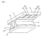
- FIG. 1 is a perspective diagram of a discharge cell of a 3-electrode AC surface discharge type PDP according to the related art.
- a discharge cell of a 3-electrodes AC surface discharge type PDP consists of a scan electrode 30Y and sustain electrode 30Z formed on an upper substrate 10 and an address electrode 20X formed on a lower substrate 18.
- Each of the scan and sustain electrodes 30Y and 30Z has a line width smaller than that of a transparent electrode 12Y or 12Z and includes a metal bus electrode 13Y or 13Z.
- the transparent electrodes 12Y and 12Z are generally formed of indium tin oxide (ITO) on the upper substrate 10.
- the metal bus electrodes 13Y and 13Z are generally formed of metal such as Cr or the like on the transparent electrodes 12Y and 12Z to reduce the voltage drops caused by the transparent electrodes 12Y and 12Z of high resistance, respectively.
- An upper dielectric layer 14 and protecting layer 16 are stacked over the upper substrate 10 including the scan and sustain electrodes 30Y and 30Z. Wall charges generated from plasma discharge are accumulated on the upper dielectric layer 14.
- the protecting layer 16 protects the upper dielectric layer 14 against sputtering caused by plasma discharge and increases discharge efficiency of secondary electrons.
- the protecting layer 16 is generally formed of MgO.
- the address electrode 20X is formed in a direction crossing with that of the scan or sustain electrode 30Y or 30Z.
- a lower dielectric layer 22 and barrier rib 24 are formed on the lower substrate 8 having the address electrode 20X formed thereon.
- a fluorescent layer 26 is formed on surfaces of the lower dielectric layer 22 and the barrier rib 24.
- the barrier rib 24 is formed parallel to the address electrode 20Z to physically partition each discharge cell and prevents UV and visible rays generated from electric discharge from leaking to neighbor discharge cells.
- the fluorescent layer 26 is excited by the UV-ray generated from plasma discharge to emit light including one of red, green, and blue visible rays.
- a mixed inert gas such as He+Xe, Ne+Xe, He+Xe+Ne, and the like for electric discharge is injected in a discharge space of the discharge cell provided between the barrier ribs 24 and the upper and lower substrates 10 and 18.
- one frame is divided into several sub-fields differing in luminous times to implement gray levels. And, each of the sub-fields is divided again into a reset period for arousing electric discharge evenly, an address period for selecting a discharge cell, and a sustain period for implementing gray levels according to a discharging number.
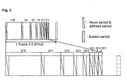
- a frame period (16.67ms) corresponding to 1/60 second is divided into eight sub-fields SF1 To SF8. And, each of the eight sub-fields SF1 to SF8 is divided into a reset period, an address period, and a sustain period.
- the sustain period varies according to the corresponding sub-field, the image gray levels can be implemented.
- the sub-fields of the frame are selected to implement the gray levels in a manner of Table 1.
- 'SFx' means an x th sub-field
- 'Yz' indicates a brightness weight set to a decimal number for the corresponding sub-field
- ' ⁇ ' indicates a turned-on state of the corresponding sub-field
- ' ⁇ ' indicates a turned-off state of the corresponding sub-field.
- the sub-fields bring about sustain discharges to correspond to the brightness weights allocated to them, respectively, thereby representing gray levels corresponding to the brightness weights, respectively.
- a discharge error may occur in the gray levels 15-16, 31-32, 63-64, and 127-128 where luminous patterns are varied more considerably than those of the previous gray levels, respectively.
- the gray levels 15-16, 31-32, 63-64, and 127-128 where luminous patterns are greatly varied, it is difficult to control wall charges.
- the sustain discharge occurs in the first to fifth sub-fields SF1 to SF5.
- the address discharge can occur stably in the selected sub-fields.
- the address discharge occurring in the fifth sub-field SF5 can take place stably due to the priming discharged particles produced from the previous sub-fields.
- the sustain discharge takes place in the sixth sub-field SF6.
- one sub-field is selected from one frame to represent the gray level of '32'.
- the address discharge occurring in the sixth sub-field SF6 should take place without the aid of charged particles produced from the previous sub-field. For such a reason, it is highly probable that the address discharge may fail in the sixth sub-field SF6.
- 10% Ne-Xe at 46kPa is set as the discharge gas sealed within the PDP to increase density of the Xe component.
- a drive voltage of the high-density Xe panel becomes higher than that of the related art low-density Xe panel, brightness can be enhanced.
- the high-density Xe panel enables to display an image of high brightness by raising the Xe component of the discharge gas.
- the drive voltage of the high-density Xe panel is set higher than that of the low-density Xe panel, it becomes more probable that the discharge failure of the high-density Xe panel may occur in the gray levels of 15-16, 31-32, 63-64, and 127-128 of which luminous patterns are varied more considerably than those of the previous gray levels, respectively.
- the invention addresses problems and disadvantages of the background art.
- An object of the present invention is to provide a method of diving a plasma display panel, by which electric discharge failure can be prevented.
- a method of driving a plasma display panel in which one frame comprises a plurality of sub-fields and which represent a gray level by making the sub-fields emitting light according to brightness weights allocated to the sub-fields comprises a step of implementing a specific gray level using a previous or next luminous pattern of the specific gray level in representing the specific gray level where none of the sub-fields of a one-step lower gray level are luminous.
- a method of driving a plasma display panel in which one frame comprises a plurality of sub-fields and which represent a gray level by making the sub-fields emitting light according to brightness weights allocated to the sub-fields comprises a step of implementing a specific gray level using a luminous pattern of a very previous gray level at an (n-1) th frame or a luminous pattern of a very next gray level at an n th frame in representing the specific gray level that none of the sub-fields of a one-step lower gray level are luminous.
- the method of driving a plasma display panel according to the present invention enables to prevent electric discharge failure and to stably display images on the PDP of high-density Xe.
- a method of driving a plasma display panel in which one frame comprises a plurality of sub-fields and which represent a gray level by making the sub-fields emitting light according to brightness weights allocated to the sub-fields includes a step of implementing a specific gray level using a previous or next luminous pattern of the specific gray level in representing the specific gray level where none of the sub-fields of a one-step lower gray level are luminous.
- the specific gray level may be the gray level where the sub-field located behind at least a fourth sub-field of the frame becomes luminous independently.
- the sub-field having the brightness weight of '1' may be located at a third sub-field.
- the specific gray level may be the gray level that the sub-field located behind at least a fifth sub-field of the frame becomes luminous independently.
- the sub-field having the brightness weight of '1' may be located at either a third sub-field or a fourth sub-field.
- a discharge gas including at least a 10% Xe gas may be included in the plasma display panel.
- the previous luminous pattern may be a luminous pattern of a very previous gray level right before the specific gray level.
- the next luminous pattern may be a luminous pattern of a very next gray level right behind the specific gray level.
- a method of driving a plasma display panel in which one frame comprises a plurality of sub-fields and which represent a gray level by making the sub-fields emitting light according to brightness weights allocated to the sub-fields includes a step of implementing a specific gray level using a luminous pattern of a very previous gray level at an (n-1) th frame or a luminous pattern of a very next gray level at an n th frame in representing the specific gray level that none of the sub-fields of a one-step lower gray level are luminous.
- the specific gray level may be the gray level where the sub-field located behind at least a fourth sub-field of the frame becomes luminous independently.
- the sub-field having the brightness weight of '1' may be located at a third sub-field.
- the specific gray level may be the gray level that the sub-field located behind at least a fifth sub-field of the frame becomes luminous independently.
- the sub-field having the brightness weight of '1' may be located at either a third sub-field or a fourth sub-field.
- a discharge gas including at least a 10% Xe gas may be included in the plasma display panel.
- one frame is divided into a plurality of sub-fields to be driven. For instance, in case of displaying an image with 256 gray levels, one frame is divided into eight sub-fields SF1 to SF8. And, each of the eight sub-fields has a separate brightness weight to represent the gray level.
- the sub-fields of the frame are selected to implement the gray levels in a manner of Table 1.
- 'SFx' means an x th sub-field
- 'Yz' indicates a brightness weight set to a decimal number for the corresponding sub-field
- ' ⁇ ' indicates a turned-on state of the corresponding sub-field
- (' indicates a turned-off state of the corresponding sub-field.
- the sub-fields bring about sustain discharges to correspond to the brightness weights allocated to them, respectively, thereby representing gray levels corresponding to the brightness weights, respectively.
- a luminous pattern of the previous gray level is maintained at a specific gray level (16, 32, 64, 128) of which luminous pattern needs to be varied more greatly than that of the very previous gray level.
- the specific gray level of which luminous pattern needs to be varied more greatly means the gray level before which the entire sub-fields of the previous gray level fail to be luminous.
- the first to fourth sub-fields SF1 to SF4 become luminous at the gray level of '15'.
- the fifth sub-field SF5 becomes luminous at the specific gray level of '16' only.
- the fifth sub-field SF5 should be luminous only to represent the gray level of '16', there occurs no sustain discharge in the sub-field prior to the fifth sub-field SF5 so that the discharge failure may take place. Yet, by representing the gray level of '16' using the same luminous pattern of the gray level of '15', discharge failure is prevented from occurring in representing the gray level of '16'. Namely, when the sub-field following the fifth or fourth sub-field of the frame is independently becomes luminous to correspond to a specific brightness weight, the gray level of a specific brightness weight is represented using the luminous pattern of the previous gray level. Hence, the described method enables to prevent the discharge failure.
- the eighth sub-field SF8 should be luminous only to corresponding to a brightness weight in representing the gray level of '128'.
- the present method represents the gray level using the luminous pattern of the gray level of '127'. In other words, the present method enables to prevent the discharge failure from occurring in representing the gray level of '128' using the luminous pattern of the gray level of '127'.
- the PDP can be stably driven without the discharge failure despite the drive voltage increase.
- embodiments of the present invention select sub-fields in a manner of Table 3 to represent the gray levels.
- 'SFx' means an x th sub-field
- 'Yz' indicates a brightness weight set to a decimal number for the corresponding sub-field
- ' ⁇ ' indicates a turned-on state of the corresponding sub-field
- ' ⁇ ' indicates a turned-off state of the corresponding sub-field.
- the sub-fields bring about sustain discharges to correspond to the brightness weights allocated to them, respectively, thereby representing gray levels corresponding to the brightness weights, respectively.
- a luminous pattern of the very next gray level is maintained at a specific gray level (16, 32, 64, 128) of which luminous pattern needs to be varied more greatly than that of the very previous gray level.
- the specific gray level of which luminous pattern needs to be varied more greatly means the gray level before which the entire sub-fields of the previous gray level fail to be luminous.
- the first to fourth sub-fields SF1 to SF4 become luminous at the gray level of '15'.
- the fifth sub-field SF5 becomes luminous at the specific gray level of '16' only.
- the fifth sub-field SF5 should be luminous only to represent the gray level of '16', there occurs no sustain discharge in the sub-field prior to the fifth sub-field SF5 so that the discharge failure may take place. Yet, by representing the gray level of '16' using the same luminous pattern of the gray level of '17', discharge failure is prevented from occurring in representing the gray level of '16'. Namely, when the sub-field following the fifth or fourth sub-field of the frame is independently becomes luminous to correspond to a specific brightness weight, the gray level of a specific brightness weight is represented using the luminous pattern of the very next gray level. Hence, the present invention enables to reduce or prevent the discharge failure.
- the eighth sub-field SF8 should be luminous only to corresponding to a brightness weight in representing the gray level of '128'. Namely, since the eighth sub-field SF8 located after at least the fifth or fourth sub-field of the frame should be independently luminous in representing the gray level of '128', the gray level is represented using the luminous pattern of the gray level of '129'. In other words, discharge failure is prevented from occurring in representing the gray level of '128' using the luminous pattern of the gray level of '129'.
- the PDP can be stably driven without the discharge failure despite the drive voltage increase.
- embodiments of the present invention enable to arrange sub-field luminous patterns in a manner of Table 4 to bring about the electric discharge more stably.
- 'SFx' means an xth sub-field and 'Yz' indicates a brightness weight set to a decimal number for the corresponding sub-field.
- the first and eighth sub-fields SF1 and SF8 are selected from Table 3. Since there exists a great timing interval between the first and eighth sub-fields SF1 and SF8, it is probable that the discharge failure may occur. Yet, if the gray level of '1' is arranged in the fourth sub-field like Table 4, the fourth and eighth sub-fields SF4 and SF8 are selected in case of representing the gray level of '128' in the manner of Table 3. Hence, the discharge failure can be prevented.
- the frame having the luminous patterns of 1, 2, 4, 8, 16, 32, 64, and 128 are taken as a reference.
- the present invention is applicable to PDP having various luminous patterns.
- the present invention is applicable to the frame having the luminous patterns of 1, 2, 4, 8, 16, 32, 64, 64, 64, and 64.
- the sub-field having the luminous pattern of '1' can be arranged in the fourth sub-field.
- mean brightness of a specific gray level as shown in FIG. 4A and FIG. 4B, can be represented.
- the gray level of '15' is represented in the (n-1)th frame (where n is a natural number) and the gray level of '17' are represented in the nth frame.
- a user recognizes an image displayed on a panel by the gray level of '16' as the mean gray level between the (n-1)th and nth frames.
- the gray level of '128' can be represented on the average in a manner of representing the gray level of '127' at the (n-1) th frame and the gray level of '129' at the nth frame.
- a method of driving a plasma display panel represents the gray level using the luminous pattern of the very previous or next gray level centering on the gray level of which gray pattern is varied more greatly than that of the previous gray level, thereby enabling to prevent the discharge failure.
- the present invention may be applied to the PDP including the discharge gas of high-density Xe, thereby enabling to display the image more stably on the PDP of the high-density Xe.
- embodiments of the present invention may arrange the sub-field having the gray level of '1' in the middle of the frame, thereby enabling to efficiently utilize the priming effect.
Landscapes
- Engineering & Computer Science (AREA)
- Physics & Mathematics (AREA)
- Computer Hardware Design (AREA)
- General Physics & Mathematics (AREA)
- Theoretical Computer Science (AREA)
- Power Engineering (AREA)
- Plasma & Fusion (AREA)
- Control Of Indicators Other Than Cathode Ray Tubes (AREA)
- Control Of Gas Discharge Display Tubes (AREA)
- Gas-Filled Discharge Tubes (AREA)
Abstract
Description
- The present invention relates to a plasma display panel, and more particularly, to a method of driving a plasma display panel.
- Generally, plasma display panels (hereinafter abbreviated as PDPs) display images including characters and graphics by exciting a fluorescent substance with 147nm ultraviolet light emitted,during electric discharge of a mixed gas such as (He + Xe), (Ne + Xe), or (He + Ne + Xe). PDPs provide excellent quality of image due to recent developments in technology, as well as permitting manufacture in slim size and wide-screen configurations. Specifically, a 3-electrode AC surface discharge type PDP lowers the voltage necessary to achieve electric discharge using wall charges accumulated on a surface and protects the electrodes from sputtering occurring on the electric discharge, thereby being advantageous in enabling low voltage driving and long endurance.
- FIG. 1 is a perspective diagram of a discharge cell of a 3-electrode AC surface discharge type PDP according to the related art. Referring to FIG. 1, a discharge cell of a 3-electrodes AC surface discharge type PDP consists of a
scan electrode 30Y and sustain electrode 30Z formed on anupper substrate 10 and anaddress electrode 20X formed on alower substrate 18. - Each of the scan and sustain
electrodes 30Y and 30Z has a line width smaller than that of atransparent electrode metal bus electrode transparent electrodes upper substrate 10. Themetal bus electrodes transparent electrodes transparent electrodes dielectric layer 14 and protectinglayer 16 are stacked over theupper substrate 10 including the scan and sustainelectrodes 30Y and 30Z. Wall charges generated from plasma discharge are accumulated on the upperdielectric layer 14. The protectinglayer 16 protects the upperdielectric layer 14 against sputtering caused by plasma discharge and increases discharge efficiency of secondary electrons. And, the protectinglayer 16 is generally formed of MgO. - The
address electrode 20X is formed in a direction crossing with that of the scan or sustainelectrode 30Y or 30Z. A lowerdielectric layer 22 andbarrier rib 24 are formed on the lower substrate 8 having theaddress electrode 20X formed thereon. Afluorescent layer 26 is formed on surfaces of the lowerdielectric layer 22 and thebarrier rib 24. Thebarrier rib 24 is formed parallel to the address electrode 20Z to physically partition each discharge cell and prevents UV and visible rays generated from electric discharge from leaking to neighbor discharge cells. Thefluorescent layer 26 is excited by the UV-ray generated from plasma discharge to emit light including one of red, green, and blue visible rays. A mixed inert gas such as He+Xe, Ne+Xe, He+Xe+Ne, and the like for electric discharge is injected in a discharge space of the discharge cell provided between thebarrier ribs 24 and the upper andlower substrates - In the above-configured 3-electrodes AC surface discharge type PDP, one frame is divided into several sub-fields differing in luminous times to implement gray levels. And, each of the sub-fields is divided again into a reset period for arousing electric discharge evenly, an address period for selecting a discharge cell, and a sustain period for implementing gray levels according to a discharging number.
- For instance, in case of displaying an image at 256 gray levels, a frame period (16.67ms) corresponding to 1/60 second is divided into eight sub-fields SF1 To SF8. And, each of the eight sub-fields SF1 to SF8 is divided into a reset period, an address period, and a sustain period. The reset and address periods of the respective sub-fields are equal to each other, whereas the sustain periods and their discharge numbers of the respective sub-fields increase at a ratio of 2n (n = 0, 1, 2, 3, 4, 5, 6, 7), respectively. As the sustain period varies according to the corresponding sub-field, the image gray levels can be implemented.
- Substantially, the sub-fields of the frame are selected to implement the gray levels in a manner of Table 1.
SF1 SF2 SF3 SF4 SF5 SF6 SF7 SF8 Y1 Y2 Y3 Y8 Y16 Y32 Y64 Y128 0 × × × × × × × × 1 ○ × × × × × × × 2 × ○ × × × × × × 15 ○ ○ ○ ○ × × × × 16 × × × × ○ × × × 17 ○ × × × ○ × × × ... 31 ○ ○ ○ ○ ○ × × × 32 × × × × × ○ × × 33 ○ × × × × ○ × × ... 63 ○ ○ ○ ○ ○ ○ × × 64 × × × × × × ○ × ... 127 ○ ○ ○ ○ ○ ○ ○ × 128 × × × × × × × ○ ... 255 ○ ○ ○ ○ ○ ○ ○ ○ - In Table 1, 'SFx' means an xth sub-field, 'Yz' indicates a brightness weight set to a decimal number for the corresponding sub-field, '○' indicates a turned-on state of the corresponding sub-field, and '×' indicates a turned-off state of the corresponding sub-field.
- The sub-fields, as shown in Table 1, bring about sustain discharges to correspond to the brightness weights allocated to them, respectively, thereby representing gray levels corresponding to the brightness weights, respectively. Yet, in the related art sub-field driving method, a discharge error may occur in the gray levels 15-16, 31-32, 63-64, and 127-128 where luminous patterns are varied more considerably than those of the previous gray levels, respectively. Moreover, in the gray levels 15-16, 31-32, 63-64, and 127-128 where luminous patterns are greatly varied, it is difficult to control wall charges.
- Specifically, in order to represent the gray level of '31', the sustain discharge occurs in the first to fifth sub-fields SF1 to SF5. In doing so, since a plurality of the sub-fields are selected from one frame to represent the gray level of '31', the address discharge can occur stably in the selected sub-fields. In other words, the address discharge occurring in the fifth sub-field SF5 can take place stably due to the priming discharged particles produced from the previous sub-fields.
- In order to represent the gray level of '32', the sustain discharge takes place in the sixth sub-field SF6. In doing so, one sub-field is selected from one frame to represent the gray level of '32'. In other words, the address discharge occurring in the sixth sub-field SF6 should take place without the aid of charged particles produced from the previous sub-field. For such a reason, it is highly probable that the address discharge may fail in the sixth sub-field SF6.
- Meanwhile, in another related art, 10% Ne-Xe at 46kPa is set as the discharge gas sealed within the PDP to increase density of the Xe component. Thus, even if a drive voltage of the high-density Xe panel becomes higher than that of the related art low-density Xe panel, brightness can be enhanced. Hence, the high-density Xe panel enables to display an image of high brightness by raising the Xe component of the discharge gas. Yet, since the drive voltage of the high-density Xe panel is set higher than that of the low-density Xe panel, it becomes more probable that the discharge failure of the high-density Xe panel may occur in the gray levels of 15-16, 31-32, 63-64, and 127-128 of which luminous patterns are varied more considerably than those of the previous gray levels, respectively.
- Accordingly, the invention addresses problems and disadvantages of the background art.
- An object of the present invention is to provide a method of diving a plasma display panel, by which electric discharge failure can be prevented.
- According to an embodiment of the present invention, a method of driving a plasma display panel in which one frame comprises a plurality of sub-fields and which represent a gray level by making the sub-fields emitting light according to brightness weights allocated to the sub-fields, comprises a step of implementing a specific gray level using a previous or next luminous pattern of the specific gray level in representing the specific gray level where none of the sub-fields of a one-step lower gray level are luminous.
- According to an embodiment of the present invention, a method of driving a plasma display panel in which one frame comprises a plurality of sub-fields and which represent a gray level by making the sub-fields emitting light according to brightness weights allocated to the sub-fields, comprises a step of implementing a specific gray level using a luminous pattern of a very previous gray level at an (n-1)th frame or a luminous pattern of a very next gray level at an nth frame in representing the specific gray level that none of the sub-fields of a one-step lower gray level are luminous.
- The method of driving a plasma display panel according to the present invention enables to prevent electric discharge failure and to stably display images on the PDP of high-density Xe.
- The invention will be described in detail with reference to the following drawings in which like numerals refer to like elements.
- FIG. 1 is a perspective diagram of a discharge cell of a 3-electrodes AC surface discharge type PDP according to a related art.
- FIG. 2 is a timing diagram of one frame in a general plasma display panel.
- FIG. 3 is a diagram of a luminous pattern of a sub-field corresponding to a brightness weight.
- FIG. 4 is a diagram of explaining a method of representing a mean gray level using two frames.
-
- Preferred embodiments of the present invention will be described in a more detailed manner with reference to the drawings.
- According to one embodiment of the present invention, a method of driving a plasma display panel in which one frame comprises a plurality of sub-fields and which represent a gray level by making the sub-fields emitting light according to brightness weights allocated to the sub-fields, includes a step of implementing a specific gray level using a previous or next luminous pattern of the specific gray level in representing the specific gray level where none of the sub-fields of a one-step lower gray level are luminous.
- The specific gray level may be the gray level where the sub-field located behind at least a fourth sub-field of the frame becomes luminous independently.
- The sub-field having the brightness weight of '1' may be located at a third sub-field.
- The specific gray level may be the gray level that the sub-field located behind at least a fifth sub-field of the frame becomes luminous independently.
- The sub-field having the brightness weight of '1' may be located at either a third sub-field or a fourth sub-field.
- A discharge gas including at least a 10% Xe gas may be included in the plasma display panel.
- The previous luminous pattern may be a luminous pattern of a very previous gray level right before the specific gray level.
- The next luminous pattern may be a luminous pattern of a very next gray level right behind the specific gray level.
- According to another embodiment of the present invention, a method of driving a plasma display panel in which one frame comprises a plurality of sub-fields and which represent a gray level by making the sub-fields emitting light according to brightness weights allocated to the sub-fields, includes a step of implementing a specific gray level using a luminous pattern of a very previous gray level at an (n-1)th frame or a luminous pattern of a very next gray level at an nth frame in representing the specific gray level that none of the sub-fields of a one-step lower gray level are luminous.
- The specific gray level may be the gray level where the sub-field located behind at least a fourth sub-field of the frame becomes luminous independently.
- The sub-field having the brightness weight of '1' may be located at a third sub-field.
- The specific gray level may be the gray level that the sub-field located behind at least a fifth sub-field of the frame becomes luminous independently.
- The sub-field having the brightness weight of '1' may be located at either a third sub-field or a fourth sub-field.
- A discharge gas including at least a 10% Xe gas may be included in the plasma display panel.
- Hereafter, the embodiuments of the present invention will be described with reference to the drawings.
- First of all, in a method of driving a plasma display panel according to the present invention, one frame is divided into a plurality of sub-fields to be driven. For instance, in case of displaying an image with 256 gray levels, one frame is divided into eight sub-fields SF1 to SF8. And, each of the eight sub-fields has a separate brightness weight to represent the gray level.
- Substantially, the sub-fields of the frame are selected to implement the gray levels in a manner of Table 1.
SF1 SF2 SF3 SF4 SF5 SF6 SF7 SF8 Y1 Y2 Y3 Y8 Y16 Y32 Y64 Y128 0 × × × × × × × × 1 ○ × × × × × × × 2 × ○ × × × × × × 15 ○ ○ ○ ○ × × × × 16 ○ ○ ○ ○ × × × × 17 ○ × × × ○ × × × ... 31 ○ ○ ○ ○ ○ × × × 32 ○ ○ ○ ○ ○ × × × 33 ○ × × × × ○ × × ... 63 ○ ○ ○ ○ ○ ○ × × 64 ○ ○ ○ ○ ○ ○ × × ... 127 ○ ○ ○ ○ ○ ○ ○ × 128 ○ ○ ○ ○ ○ ○ ○ × ... 255 ○ ○ ○ ○ ○ ○ ○ ○ - In Table 2, 'SFx' means an xth sub-field, 'Yz' indicates a brightness weight set to a decimal number for the corresponding sub-field, '○' indicates a turned-on state of the corresponding sub-field, and (' indicates a turned-off state of the corresponding sub-field.
- The sub-fields, as shown in Table 2, bring about sustain discharges to correspond to the brightness weights allocated to them, respectively, thereby representing gray levels corresponding to the brightness weights, respectively. In the present sub-field driving method, a luminous pattern of the previous gray level is maintained at a specific gray level (16, 32, 64, 128) of which luminous pattern needs to be varied more greatly than that of the very previous gray level. In this case, the specific gray level of which luminous pattern needs to be varied more greatly means the gray level before which the entire sub-fields of the previous gray level fail to be luminous. In other words, the first to fourth sub-fields SF1 to SF4 become luminous at the gray level of '15'. Yet, the fifth sub-field SF5 becomes luminous at the specific gray level of '16' only.
- Specifically, since the fifth sub-field SF5 should be luminous only to represent the gray level of '16', there occurs no sustain discharge in the sub-field prior to the fifth sub-field SF5 so that the discharge failure may take place. Yet, by representing the gray level of '16' using the same luminous pattern of the gray level of '15', discharge failure is prevented from occurring in representing the gray level of '16'. Namely, when the sub-field following the fifth or fourth sub-field of the frame is independently becomes luminous to correspond to a specific brightness weight, the gray level of a specific brightness weight is represented using the luminous pattern of the previous gray level. Hence, the described method enables to prevent the discharge failure.
- For another instance, the eighth sub-field SF8 should be luminous only to corresponding to a brightness weight in representing the gray level of '128'. Namely, since the eighth sub-field SF8 located behind at least the fifth or fourth sub-field of the frame should be independently luminous in representing the gray level of '128', the present method represents the gray level using the luminous pattern of the gray level of '127'. In other words, the present method enables to prevent the discharge failure from occurring in representing the gray level of '128' using the luminous pattern of the gray level of '127'.
- Thus, if the driving method is applied to the high-density Xe (over 10%), the PDP can be stably driven without the discharge failure despite the drive voltage increase.
- Besides, embodiments of the present invention select sub-fields in a manner of Table 3 to represent the gray levels.
SF1 SF2 SF3 SF4 SF5 SF6 SF7 SF8 Y1 Y2 Y3 Y8 Y16 Y32 Y64 Y128 0 × × × × × × × × 1 ○ × × × × × × × 2 × ○ × × × × × × 15 ○ ○ ○ ○ × × × × 16 ○ × × × ○ × × × 17 ○ × × × ○ × × × ... 31 ○ ○ ○ ○ ○ × × × 32 ○ × × × × ○ × × 33 ○ × × × × ○ × × ... 63 ○ ○ ○ ○ ○ ○ × × 64 ○ × × × × × ○ × ... 127 ○ ○ ○ ○ ○ ○ ○ × 128 ○ × × × × × × ○ ... 255 ○ ○ ○ ○ ○ ○ ○ ○ - In Table 3, 'SFx' means an xth sub-field, 'Yz' indicates a brightness weight set to a decimal number for the corresponding sub-field, '○' indicates a turned-on state of the corresponding sub-field, and '×' indicates a turned-off state of the corresponding sub-field.
- The sub-fields, as shown in Table 3, bring about sustain discharges to correspond to the brightness weights allocated to them, respectively, thereby representing gray levels corresponding to the brightness weights, respectively. In the sub-field driving method, a luminous pattern of the very next gray level is maintained at a specific gray level (16, 32, 64, 128) of which luminous pattern needs to be varied more greatly than that of the very previous gray level. In this case, the specific gray level of which luminous pattern needs to be varied more greatly means the gray level before which the entire sub-fields of the previous gray level fail to be luminous. In other words, the first to fourth sub-fields SF1 to SF4 become luminous at the gray level of '15'. Yet, the fifth sub-field SF5 becomes luminous at the specific gray level of '16' only.
- Specifically, since the fifth sub-field SF5 should be luminous only to represent the gray level of '16', there occurs no sustain discharge in the sub-field prior to the fifth sub-field SF5 so that the discharge failure may take place. Yet, by representing the gray level of '16' using the same luminous pattern of the gray level of '17', discharge failure is prevented from occurring in representing the gray level of '16'. Namely, when the sub-field following the fifth or fourth sub-field of the frame is independently becomes luminous to correspond to a specific brightness weight, the gray level of a specific brightness weight is represented using the luminous pattern of the very next gray level. Hence, the present invention enables to reduce or prevent the discharge failure.
- For another instance, the eighth sub-field SF8 should be luminous only to corresponding to a brightness weight in representing the gray level of '128'. Namely, since the eighth sub-field SF8 located after at least the fifth or fourth sub-field of the frame should be independently luminous in representing the gray level of '128', the gray level is represented using the luminous pattern of the gray level of '129'. In other words, discharge failure is prevented from occurring in representing the gray level of '128' using the luminous pattern of the gray level of '129'.
- Thus, if the driving method is applied to the high-density Xe (over 10%), the PDP can be stably driven without the discharge failure despite the drive voltage increase.
- Besides, embodiments of the present invention enable to arrange sub-field luminous patterns in a manner of Table 4 to bring about the electric discharge more stably.
SF1 SF2 SF3 SF4 SF5 SF6 SF7 SF8 Y2 Y3 Y8 Y1 Y16 Y32 Y64 Y128 - In Table 4, 'SFx' means an xth sub-field and 'Yz' indicates a brightness weight set to a decimal number for the corresponding sub-field.
- Referring to Table 4, by arranging the sub-field representing the gray level of '1' in the middle of the frame, it is able to bring about the electric discharge more stably in representing the gray level in the manner of Table 3. In other words, by arranging the sub-field representing the gray level of '1' in the fourth field SF4 prior to a first specific gray level, e.g., '16', of which luminous pattern needs to be greatly varied in the frame, it is able to bring about the discharge more stably. Namely, by arranging the sub-field representing the gray level of '1', which becomes most frequently luminous in probability, in the fourth sub-field, it is able to utilize the priming effect more efficiently. Substantially, in case of representing the gray level of '128' in the manner of Table 3, the first and eighth sub-fields SF1 and SF8 are selected from Table 3. Since there exists a great timing interval between the first and eighth sub-fields SF1 and SF8, it is probable that the discharge failure may occur. Yet, if the gray level of '1' is arranged in the fourth sub-field like Table 4, the fourth and eighth sub-fields SF4 and SF8 are selected in case of representing the gray level of '128' in the manner of Table 3. Hence, the discharge failure can be prevented.
- For convenience of explanation, the frame having the luminous patterns of 1, 2, 4, 8, 16, 32, 64, and 128 are taken as a reference. Yet, the present invention is applicable to PDP having various luminous patterns. For instance, the present invention is applicable to the frame having the luminous patterns of 1, 2, 4, 8, 16, 32, 64, 64, 64, and 64. In this case, the sub-field having the luminous pattern of '1' can be arranged in the fourth sub-field.
- Meanwhile, mean brightness of a specific gray level, as shown in FIG. 4A and FIG. 4B, can be represented. Specifically, in order to represent the gray level of '16', the gray level of '15' is represented in the (n-1)th frame (where n is a natural number) and the gray level of '17' are represented in the nth frame. In doing so, a user recognizes an image displayed on a panel by the gray level of '16' as the mean gray level between the (n-1)th and nth frames. Likewise, in order to represent the gray level of '128', the gray level of '128' can be represented on the average in a manner of representing the gray level of '127' at the (n-1) th frame and the gray level of '129' at the nth frame.
- As mentioned in the foregoing description, a method of driving a plasma display panel according to the present invention represents the gray level using the luminous pattern of the very previous or next gray level centering on the gray level of which gray pattern is varied more greatly than that of the previous gray level, thereby enabling to prevent the discharge failure. Specifically, the present invention may be applied to the PDP including the discharge gas of high-density Xe, thereby enabling to display the image more stably on the PDP of the high-density Xe. Moreover, embodiments of the present invention may arrange the sub-field having the gray level of '1' in the middle of the frame, thereby enabling to efficiently utilize the priming effect.
- Embodiments of the invention being thus described, it will be obvious that the same may be varied in many ways. Such variations are not to be regarded as a departure from the scope of the invention, and all such modifications as would be obvious to one skilled in the art are intended to be included within the scope of the following claims.
Claims (11)
- A method of driving a plasma display panel in which one frame comprises a plurality of sub-fields and which represent a gray level by making the sub-fields emit light according to brightness weights allocated to the sub-fields, wherein
the method includes a step of implementing a specific gray level using a previous or next luminous pattern of the specific gray level in representing the specific gray level where none of the sub-fields of a one-step lower gray level are luminous. - A method of driving a plasma display panel in which one frame comprises a plurality of sub-fields and which represent a gray level by making the sub-fields emitting light according to brightness weights allocated to the sub-fields, wherein
the method includes a step of implementing a specific gray level using a luminous pattern of a very previous gray level at an (n-1)th frame or a luminous pattern of a very next gray level at an nth frame in representing the specific gray level that none of the sub-fields of a one-step lower gray level are luminous. - The method of claim 1 or 2, wherein the specific gray level is the gray level where the sub-field located behind at least a fourth sub-field of the frame becomes luminous independently.
- The method of claim 3, wherein the sub-field having the brightness weight of '1' is located at a third sub-field.
- The method of claim 1 or 2, wherein the specific gray level is the gray level that the sub-field located behind at least a fifth sub-field of the frame becomes luminous independently.
- The method of claim 5, wherein the sub-field having the brightness weight of '1' is located at either a third sub-field or a fourth sub-field.
- The method of claim 1 or 2, wherein a discharge gas including at least a 10% Xe gas is included in the plasma display panel.
- The method of claim 1, wherein the previous luminous pattern is a luminous pattern of a very previous gray level right before the specific gray level.
- The method of claim 1, wherein the next luminous pattern is a luminous pattern of a very next gray level right behind the specific gray level.
- Apparatus for driving a plasma display panel comprising means for putting into effect the method steps of any of claims 1 to 9.
- A visual display unit comprising a plasma display panel and the apparatus of claim 10.
Applications Claiming Priority (2)
| Application Number | Priority Date | Filing Date | Title |
|---|---|---|---|
| KR2003069166 | 2003-10-06 | ||
| KR1020030069166A KR20050033197A (en) | 2003-10-06 | 2003-10-06 | Method of driving plasma display panel |
Publications (2)
| Publication Number | Publication Date |
|---|---|
| EP1522987A2 true EP1522987A2 (en) | 2005-04-13 |
| EP1522987A3 EP1522987A3 (en) | 2006-08-23 |
Family
ID=34309549
Family Applications (1)
| Application Number | Title | Priority Date | Filing Date |
|---|---|---|---|
| EP04256033A Ceased EP1522987A3 (en) | 2003-10-06 | 2004-09-30 | Method of driving a plasma display panel |
Country Status (6)
| Country | Link |
|---|---|
| US (1) | US7688284B2 (en) |
| EP (1) | EP1522987A3 (en) |
| JP (1) | JP2005115378A (en) |
| KR (1) | KR20050033197A (en) |
| CN (1) | CN100397453C (en) |
| TW (1) | TWI291678B (en) |
Families Citing this family (3)
| Publication number | Priority date | Publication date | Assignee | Title |
|---|---|---|---|---|
| KR100707187B1 (en) * | 2005-04-21 | 2007-04-13 | 삼성전자주식회사 | Gallium Nitride Compound Semiconductor Device |
| KR20090037675A (en) * | 2007-10-12 | 2009-04-16 | 삼성전자주식회사 | Image signal processing device and image signal processing method |
| KR20120012483A (en) * | 2009-06-15 | 2012-02-09 | 파나소닉 주식회사 | Driving Method of Plasma Display Panel and Plasma Display Device |
Citations (2)
| Publication number | Priority date | Publication date | Assignee | Title |
|---|---|---|---|---|
| EP0893916A2 (en) * | 1997-07-24 | 1999-01-27 | Matsushita Electric Industrial Co., Ltd. | Image display apparatus and image evaluation apparatus |
| EP1182635A2 (en) * | 2000-08-23 | 2002-02-27 | Matsushita Electric Industrial Co., Ltd. | Control device for addressing a display panel with reduced electric consumption |
Family Cites Families (13)
| Publication number | Priority date | Publication date | Assignee | Title |
|---|---|---|---|---|
| JP3719783B2 (en) * | 1996-07-29 | 2005-11-24 | 富士通株式会社 | Halftone display method and display device |
| JPH1062762A (en) * | 1996-08-22 | 1998-03-06 | Sony Corp | Plasma addressed liquid crystal display |
| JP3417246B2 (en) * | 1996-09-25 | 2003-06-16 | 日本電気株式会社 | Gradation display method |
| JP3712802B2 (en) * | 1996-10-29 | 2005-11-02 | 富士通株式会社 | Halftone display method and display device |
| DE69842070D1 (en) * | 1997-04-02 | 2011-02-03 | Panasonic Corp | Image display device |
| JP3591623B2 (en) * | 1997-04-26 | 2004-11-24 | パイオニア株式会社 | Driving method of plasma display panel |
| US6369782B2 (en) * | 1997-04-26 | 2002-04-09 | Pioneer Electric Corporation | Method for driving a plasma display panel |
| JP3201997B2 (en) * | 1998-12-14 | 2001-08-27 | 松下電器産業株式会社 | Plasma display device |
| US6597120B1 (en) * | 1999-08-17 | 2003-07-22 | Lg Electronics Inc. | Flat-panel display with controlled sustaining electrodes |
| EP1256924B1 (en) * | 2001-05-08 | 2013-09-25 | Deutsche Thomson-Brandt Gmbh | Method and apparatus for processing video pictures |
| JP2003066901A (en) | 2001-08-30 | 2003-03-05 | Matsushita Electric Ind Co Ltd | Plasma display device |
| JP2003177699A (en) * | 2001-10-03 | 2003-06-27 | Matsushita Electric Ind Co Ltd | Plasma display panel driving method, plasma display panel driving device, and plasma display display device |
| JP2003173161A (en) * | 2001-12-05 | 2003-06-20 | Matsushita Electric Ind Co Ltd | Plasma display device |
-
2003
- 2003-10-06 KR KR1020030069166A patent/KR20050033197A/en not_active Ceased
-
2004
- 2004-09-30 EP EP04256033A patent/EP1522987A3/en not_active Ceased
- 2004-10-01 US US10/954,274 patent/US7688284B2/en not_active Expired - Fee Related
- 2004-10-01 TW TW093129882A patent/TWI291678B/en not_active IP Right Cessation
- 2004-10-04 JP JP2004290907A patent/JP2005115378A/en active Pending
- 2004-10-08 CN CNB2004100834014A patent/CN100397453C/en not_active Expired - Fee Related
Patent Citations (2)
| Publication number | Priority date | Publication date | Assignee | Title |
|---|---|---|---|---|
| EP0893916A2 (en) * | 1997-07-24 | 1999-01-27 | Matsushita Electric Industrial Co., Ltd. | Image display apparatus and image evaluation apparatus |
| EP1182635A2 (en) * | 2000-08-23 | 2002-02-27 | Matsushita Electric Industrial Co., Ltd. | Control device for addressing a display panel with reduced electric consumption |
Also Published As
| Publication number | Publication date |
|---|---|
| CN100397453C (en) | 2008-06-25 |
| US7688284B2 (en) | 2010-03-30 |
| US20050073481A1 (en) | 2005-04-07 |
| JP2005115378A (en) | 2005-04-28 |
| TWI291678B (en) | 2007-12-21 |
| EP1522987A3 (en) | 2006-08-23 |
| KR20050033197A (en) | 2005-04-12 |
| CN1606053A (en) | 2005-04-13 |
| TW200518009A (en) | 2005-06-01 |
Similar Documents
| Publication | Publication Date | Title |
|---|---|---|
| KR100381270B1 (en) | Method of Driving Plasma Display Panel | |
| EP0945844A2 (en) | Display and method of driving the display | |
| KR100604275B1 (en) | Driving Method of Plasma Display Panel | |
| US20030214463A1 (en) | Method for driving plasma display panel | |
| EP1484739A2 (en) | Method for driving a three-electrode plasma display panel with application of DC voltage to address electrodes during the sustain period | |
| KR100524309B1 (en) | Driving method of plasma display panel | |
| EP1522987A2 (en) | Method of driving a plasma display panel | |
| JP4719463B2 (en) | Driving method of plasma display panel | |
| KR20040065710A (en) | Driving method of plasma display panel | |
| EP1524645B1 (en) | Method and apparatus for driving a plasma display panel | |
| KR100438912B1 (en) | Driving method of plasma display panel | |
| KR100581921B1 (en) | Plasma display panel | |
| KR20030083362A (en) | Driving method of plasma display panel | |
| KR100482349B1 (en) | Method And Apparatus Of Driving Plasma Display Panel | |
| KR100574368B1 (en) | Data integrated circuit and driving device of plasma display panel using same | |
| KR100553934B1 (en) | Driving Method of Plasma Display Panel | |
| KR100612505B1 (en) | Driving Method of Plasma Display Panel | |
| KR100480470B1 (en) | Driving method of plasma display panel | |
| US20070236416A1 (en) | Method of driving plasma display panel | |
| KR100511794B1 (en) | Method for driving plasma display panel | |
| KR20030014884A (en) | Plasma display panel and driving method thereof | |
| KR100438920B1 (en) | METHOD Of DRIVING PLASMA DISPLAY PANEL | |
| KR20030062798A (en) | Plasma display panel | |
| KR20030079485A (en) | Driving method of plasma display panel | |
| KR20080055235A (en) | Plasma display device and driving method thereof |
Legal Events
| Date | Code | Title | Description |
|---|---|---|---|
| PUAI | Public reference made under article 153(3) epc to a published international application that has entered the european phase |
Free format text: ORIGINAL CODE: 0009012 |
|
| AK | Designated contracting states |
Kind code of ref document: A2 Designated state(s): AT BE BG CH CY CZ DE DK EE ES FI FR GB GR HU IE IT LI LU MC NL PL PT RO SE SI SK TR |
|
| AX | Request for extension of the european patent |
Extension state: AL HR LT LV MK |
|
| RIN1 | Information on inventor provided before grant (corrected) |
Inventor name: CHUNG, MOON SHICK Inventor name: KIM, YOUNG DAEPDP DEVELOPMENT SECTION, PDP DEPT. |
|
| PUAL | Search report despatched |
Free format text: ORIGINAL CODE: 0009013 |
|
| AK | Designated contracting states |
Kind code of ref document: A3 Designated state(s): AT BE BG CH CY CZ DE DK EE ES FI FR GB GR HU IE IT LI LU MC NL PL PT RO SE SI SK TR |
|
| AX | Request for extension of the european patent |
Extension state: AL HR LT LV MK |
|
| 17P | Request for examination filed |
Effective date: 20060816 |
|
| 17Q | First examination report despatched |
Effective date: 20061102 |
|
| AKX | Designation fees paid |
Designated state(s): DE FR GB NL |
|
| STAA | Information on the status of an ep patent application or granted ep patent |
Free format text: STATUS: THE APPLICATION HAS BEEN REFUSED |
|
| 18R | Application refused |
Effective date: 20091207 |