EP1522964B1 - Verfahren zum Bearbeiten von Videobildern zur Kompensation des Falschkontureffekts und Dithering-Rauschens - Google Patents
Verfahren zum Bearbeiten von Videobildern zur Kompensation des Falschkontureffekts und Dithering-Rauschens Download PDFInfo
- Publication number
- EP1522964B1 EP1522964B1 EP04021788A EP04021788A EP1522964B1 EP 1522964 B1 EP1522964 B1 EP 1522964B1 EP 04021788 A EP04021788 A EP 04021788A EP 04021788 A EP04021788 A EP 04021788A EP 1522964 B1 EP1522964 B1 EP 1522964B1
- Authority
- EP
- European Patent Office
- Prior art keywords
- video
- gradient
- level
- code words
- picture
- Prior art date
- Legal status (The legal status is an assumption and is not a legal conclusion. Google has not performed a legal analysis and makes no representation as to the accuracy of the status listed.)
- Expired - Lifetime
Links
Images


Classifications
-
- G—PHYSICS
- G06—COMPUTING OR CALCULATING; COUNTING
- G06T—IMAGE DATA PROCESSING OR GENERATION, IN GENERAL
- G06T9/00—Image coding
-
- G—PHYSICS
- G09—EDUCATION; CRYPTOGRAPHY; DISPLAY; ADVERTISING; SEALS
- G09G—ARRANGEMENTS OR CIRCUITS FOR CONTROL OF INDICATING DEVICES USING STATIC MEANS TO PRESENT VARIABLE INFORMATION
- G09G3/00—Control arrangements or circuits, of interest only in connection with visual indicators other than cathode-ray tubes
- G09G3/20—Control arrangements or circuits, of interest only in connection with visual indicators other than cathode-ray tubes for presentation of an assembly of a number of characters, e.g. a page, by composing the assembly by combination of individual elements arranged in a matrix no fixed position being assigned to or needed to be assigned to the individual characters or partial characters
- G09G3/2007—Display of intermediate tones
- G09G3/2018—Display of intermediate tones by time modulation using two or more time intervals
- G09G3/2022—Display of intermediate tones by time modulation using two or more time intervals using sub-frames
- G09G3/2029—Display of intermediate tones by time modulation using two or more time intervals using sub-frames the sub-frames having non-binary weights
-
- G—PHYSICS
- G09—EDUCATION; CRYPTOGRAPHY; DISPLAY; ADVERTISING; SEALS
- G09G—ARRANGEMENTS OR CIRCUITS FOR CONTROL OF INDICATING DEVICES USING STATIC MEANS TO PRESENT VARIABLE INFORMATION
- G09G3/00—Control arrangements or circuits, of interest only in connection with visual indicators other than cathode-ray tubes
- G09G3/20—Control arrangements or circuits, of interest only in connection with visual indicators other than cathode-ray tubes for presentation of an assembly of a number of characters, e.g. a page, by composing the assembly by combination of individual elements arranged in a matrix no fixed position being assigned to or needed to be assigned to the individual characters or partial characters
- G09G3/2007—Display of intermediate tones
- G09G3/2044—Display of intermediate tones using dithering
-
- G—PHYSICS
- G09—EDUCATION; CRYPTOGRAPHY; DISPLAY; ADVERTISING; SEALS
- G09G—ARRANGEMENTS OR CIRCUITS FOR CONTROL OF INDICATING DEVICES USING STATIC MEANS TO PRESENT VARIABLE INFORMATION
- G09G2320/00—Control of display operating conditions
- G09G2320/02—Improving the quality of display appearance
- G09G2320/0266—Reduction of sub-frame artefacts
-
- G—PHYSICS
- G09—EDUCATION; CRYPTOGRAPHY; DISPLAY; ADVERTISING; SEALS
- G09G—ARRANGEMENTS OR CIRCUITS FOR CONTROL OF INDICATING DEVICES USING STATIC MEANS TO PRESENT VARIABLE INFORMATION
- G09G2320/00—Control of display operating conditions
- G09G2320/02—Improving the quality of display appearance
- G09G2320/0271—Adjustment of the gradation levels within the range of the gradation scale, e.g. by redistribution or clipping
- G09G2320/0276—Adjustment of the gradation levels within the range of the gradation scale, e.g. by redistribution or clipping for the purpose of adaptation to the characteristics of a display device, i.e. gamma correction
-
- G—PHYSICS
- G09—EDUCATION; CRYPTOGRAPHY; DISPLAY; ADVERTISING; SEALS
- G09G—ARRANGEMENTS OR CIRCUITS FOR CONTROL OF INDICATING DEVICES USING STATIC MEANS TO PRESENT VARIABLE INFORMATION
- G09G3/00—Control arrangements or circuits, of interest only in connection with visual indicators other than cathode-ray tubes
- G09G3/20—Control arrangements or circuits, of interest only in connection with visual indicators other than cathode-ray tubes for presentation of an assembly of a number of characters, e.g. a page, by composing the assembly by combination of individual elements arranged in a matrix no fixed position being assigned to or needed to be assigned to the individual characters or partial characters
- G09G3/22—Control arrangements or circuits, of interest only in connection with visual indicators other than cathode-ray tubes for presentation of an assembly of a number of characters, e.g. a page, by composing the assembly by combination of individual elements arranged in a matrix no fixed position being assigned to or needed to be assigned to the individual characters or partial characters using controlled light sources
- G09G3/28—Control arrangements or circuits, of interest only in connection with visual indicators other than cathode-ray tubes for presentation of an assembly of a number of characters, e.g. a page, by composing the assembly by combination of individual elements arranged in a matrix no fixed position being assigned to or needed to be assigned to the individual characters or partial characters using controlled light sources using luminous gas-discharge panels, e.g. plasma panels
Definitions
- the present invention relates to a method and an apparatus for processing video pictures especially for dynamic false contour effect and dithering noise compensation.
- the plasma display technology now makes it possible to achieve flat colour panels of large size and with limited depth without any viewing angle constraints.
- the size of the displays may be much larger than the classical CRT picture tubes would have ever allowed.
- Plasma Display Panel utilizes a matrix array of discharge cells, which could only be "on” or “off'. Therefore, unlike a Cathode Ray Tube display or a Liquid Crystal Display in which gray levels are expressed by analog control of the light emission, a PDP controls gray level by a Pulse Width Modulation of each cell. This time-modulation will be integrated by the eye over a period corresponding to the eye time response. The more often a cell is switched on in a given time frame, the higher is its luminance or brightness. Let us assume that we want to dispose of 8 bit luminance levels i.e 255 levels per color. In that case, each level can be represented by a combination of 8 bits with the following weights: 1 - 2 - 4 - 8 - 16 - 32 - 64 - 128
- the frame period can be divided in 8 lighting sub-periods, called subfields, each corresponding to a bit and a brightness level.
- the number of light pulses for the bit “2" is the double as for the bit "1"; the number of light pulses for the bit “4" is the double as for the bit "2" and so on...
- these 8 sub-periods it is possible through combination to build the 256 gray levels.
- the eye of the observers will integrate over a frame period these sub-periods to catch the impression of the right gray level.
- the figure 1 shows such a frame with eight subfields.
- the light emission pattern introduces new categories of image-quality degradation corresponding to disturbances of gray levels and colors. These will be defined as “dynamic false contour effect” since it corresponds to disturbances of gray levels and colors in the form of an apparition of colored edges in the picture when an observation point on the PDP screen moves. Such failures on a picture lead to the impression of strong contours appearing on homogeneous area.
- the degradation is enhanced when the picture has a smooth gradation, for example like skin, and when the light-emission period exceeds several milliseconds.
- the problem is to define what "close codes" means; different definitions can be taken, but most of them will lead to the same results. Otherwise, it is important to keep a maximum of levels in order to keep a good video quality.
- the minimum of chosen levels should be equal to twice the number of subfields.
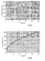
- the human eye integrates the light emitted by Pulse Width Modulation. So if you consider all video levels encoded with a basic code, the temporal center of gravity of the light generation for a subfield code is not growing with the video level. This is illustrated by the figure 2.
- the temporal center of gravity CG2 of the subfield code corresponding a video level 2 is superior to the temporal center of gravity CG3 of the subfield code corresponding a video level 3 even if 3 is more luminous than 2. This discontinuity in the light emission pattern (growing levels have not growing gravity center) introduces false contour.
- GCC Gravity Center Coding
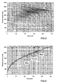
- the problem is that the whole picture has a different behavior depending on its content. Indeed, in area having smooth gradation like on the skin, it is important to have as many code words as possible to reduce the dithering noise. Furthermore, those areas are mainly based on a continuous gradation of neighboring levels that fits very well to the general concept of GCC as shown on figure 7.
- the video level of a skin area is presented. It is easy to see that all levels are near together and could be found easily on the GCC curve presented.
- the figure 8 shows the video level range for Red, Blue and Green mandatory to reproduce the smooth skin gradation on the woman forehead.
- the GCC is based on 40 code words.
- the main idea of this invention is to divide the picture to be displayed in areas of at least two types, for example low video gradient areas and high video gradient areas, to allocate a different set of GCC code words to each type of area, the set allocated to a type of area being dedicated to reduce false contours and dithering noise in the area of this type, and to encode the video levels of each area of the picture to be displayed with the allocated set of GCC code words.
- GCC code words for coding the picture.
- a specific set of GCC code words is allocated to each type of area of the picture. For example, a first set is allocated to smooth areas with low video gradient of the picture and a second set is allocated to high video gradient areas of the picture.
- the values and the number of subfield code words in the sets are chosen to reduce false contours and dithering noise in the corresponding areas.
- the first set of GCC code words comprises q different code words corresponding to q different video levels and the second set comprises less code words, for example r code words with r ⁇ q ⁇ n.
- This second set is preferably a direct subset of the first set in order to make invisible any change between one coding and another.
- the first set is chosen to be a good compromise between dithering noise reduction and false contours reduction.
- the second set which is a subset of the first set, is chosen to be more robust against false contours.
- the first set used for low video level gradient areas, comprises for example the 38 following code words. Their value of center of gravity is indicated on the right side of the following table.
- the second set used for high video level gradient areas, comprises the 11 following code words.
- level 0 Coded in 0 0 0 0 0 0 0 0 0 0 0 0 0 Center of gravity 0 level 1 Coded in 1 0 0 0 0 0 0 0 0 0 0 Center of gravity : 575 level 4 Coded in 1 0 1 0 0 0 0 0 0 0 0 0 Center of gravity : 1460 level 9 Coded in 1 0 1 1 0 0 0 0 0 0 0 0 Center of gravity : 1962 level 17 Coded in 1 0 1 1 1 0 0 0 0 0 0 0 0 Center of gravity : 2450
- Levels 1 and 4 will introduce no false contour between them since the code 1 (1 0 0 0 0 0 0 0 0 0 0 0) is included in the code 4 (1 0 1 0 0 0 0 0 0 0 0 0). It is also true for levels 1 and 9 and levels 1 and 17 since both 9 and 17 are starting with 1 0. It is also true for levels 4 and 9 and levels 4 and 17 since both 9 and 17 are starting with 1 1, which represents the level 4. In fact, if we compare all these levels 1, 4, 9 and 17, we can observe that they will introduce absolutely no false contour between them. Indeed, if a level M is bigger than level N, then the first bits of level N up to the last bit to 1 of the code of the level N are included in level M as they are.
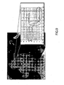
- the main idea of the concept is to analyze the video gradient around the current pixel in order to be able to select the appropriate encoding approach.
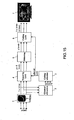
- a device implementing the invention is presented on figure 15.
- the output signal of this block is preferably more than 12 bits to be able to render correctly low video levels.
- It is forwarded to a gradient extraction block 2, which is one of the filters presented before. In theory, it is also possible to perform the gradient extraction before the gamma correction.
- the gradient extraction itself can be simplified by using only the Most Significant Bits (MSB) of the incoming signal (e.g. 6 highest bits).
- MSB Most Significant Bits
- the extracted gradient level is sent to a coding selection block 3, which selects the appropriate GCC coding set to be used. Based on this selected mode, a reseating LUT 4 and a coding LUT 6 are updated. Between them, a dithering block 7 adds more than 4 bits dithering to correctly render the video signal. It should be noticed that the output of the reseating block 4 is p x 8 bits where p represents the total amount of GCC code words used (from 40 to 11 in our example). The 8 additional bits are used for dithering purposes in order to have only p levels after dithering for the encoding block.
Landscapes
- Engineering & Computer Science (AREA)
- Physics & Mathematics (AREA)
- General Physics & Mathematics (AREA)
- Theoretical Computer Science (AREA)
- Computer Hardware Design (AREA)
- Multimedia (AREA)
- Control Of Indicators Other Than Cathode Ray Tubes (AREA)
- Control Of Gas Discharge Display Tubes (AREA)
Claims (12)
- Verfahren zum Verarbeiten von Videobildern insbesondere im Hinblick auf dynamische Falschkontureffekt- und Dithering-Rauschen-Kompensation, wobei jedes der Videobilder aus Pixeln mit mindestens einer RGB-Farbkomponente besteht, wobei die Farbkomponentenwerte digital mit einem digitalen Codewort codiert werden, im folgenden als Teilfeldcodewort bezeichnet, wobei jedes Bit eines Teilfeldcodeworts einer bestimmten Dauer zugeordnet wird, im weiteren als Teilfeld bezeichnet, während der eine Farbkomponente des Pixels zur Lichterzeugung aktiviert werden kann,
dadurch gekennzeichnet, daß es die folgenden Schritte umfaßt:- Unterteilen jedes der Videobilder in Bereiche von mindestens zwei Typen gemäß dem Videogradienten des Bilds, wobei ein spezifischer Videogradientenbereich jedem Typ von Bereich zugewiesen wird,- Bestimmen einer spezifischen Menge von Teilfeldcodewörtern, die dafür bestimmt sind, die Falschkontureffekte und/oder das Dithering-Rauschen in den Bereichen des Typs zu reduzieren, für jeden Typ von Bereich,- Codieren der Pixel jedes Bereichs des Bilds mit der entsprechenden Menge von Teilfeldcodewörtern. - Verfahren nach Anspruch 1, dadurch gekennzeichnet, daß in jeder Menge von Teilfeldcodewörtern der zeitliche Schwerpunkt CGi für die Lichterzeugung der Teilfeldcodewörter stetig mit dem entsprechenden Videopegel wächst, außer für den niedrigen Videopegelbereich bis zu einer ersten vordefinierten Grenze und/oder in dem hohen Videopegelbereich ab einer zweiten vordefinierten Grenze.
- Verfahren nach Anspruch 2, dadurch gekennzeichnet, daß die Videogradientenbereiche nicht-überlappend sind und daß die Anzahl von Codes in den Mengen von Teilfeldcodewörtern abnimmt, während der durchschnittliche Gradient des entsprechenden Videogradientenbereichs höher wird.
- Verfahren nach Anspruch 3, dadurch gekennzeichnet, daß eine erste Menge von Teilfeldcodewörtern für den Videogradientenbereich mit den höchsten Gradientenwerten definiert wird und daß die anderen Mengen Teilmengen dieser ersten Menge sind.
- Verfahren nach Anspruch 4, dadurch gekennzeichnet, daß die für einen spezifischen Videogradientenbereich definierte Menge von Teilfeldcodewörtern eine Teilmenge der Menge ist, die für den benachbarten Videogradientenbereich mit niedrigeren Gradientenwerten definiert ist.
- Verfahren nach einem der Ansprüche 2 bis 5, dadurch gekennzeichnet, daß die Teilfeldcodewörter der dem Videogradientenbereich mit dem höchsten Videogradienten zugeordneten Menge derart bestimmt werden, daß in mindestens einer Teilmenge von aufeinanderfolgenden Videopegeln der Menge das Teilfeldcodewort eines Videopegels mindestens die Bits bis "1" des Teilfeldcodeworts des benachbarten niedrigeren Videopegels in der Menge enthält.
- Verfahren nach einem der Ansprüche 2 bis 6, dadurch gekennzeichnet, daß zum Unterteilen des Videobilds in Bereiche gemäß dem Videogradienten des Bilds das Bild von einem Gradientenextraktionsfilter gefiltert wird.
- Verfahren nach Anspruch 7, dadurch gekennzeichnet, daß der Gradientenextraktionsfilter ein horizontaler Filter ist.
- Verfahren nach einem der Ansprüche 2 bis 8, wobei die erste vordefinierte Grenze etwa 10% des maximalen Videopegels beträgt und/oder die zweite vordefinierte Grenze etwa 80% des maximalen Videopegels beträgt.
- Vorrichtung zum Verarbeiten von Videobildern insbesondere im Hinblick auf dynamische Falschkontureffekt- und Dithering-Rauschen-Kompensation, wobei jedes der Videobilder aus Pixeln mit mindestens einer RGB-Farbkomponente besteht, umfassend:- erste Mittel (1, 4) zum digitalen Codieren der mindestens einen Farbkomponentenwerte mit einem digitalen Codewort, im weiteren als Teilfeldcodewort bezeichnet, wobei jedem Bit eines Teilfeldcodeworts eine bestimmte Dauer zugeteilt ist, im weiteren als Teilfeld bezeichnet, während der eine Farbkomponente des Pixels zur Lichterzeugung aktiviert werden kann,dadurch gekennzeichnet, daß sie weiterhin folgendes umfaßt:- einen Gradientenextraktionsblock (2) zum Zerlegen jedes der Videobilder in Bereiche von mindestens zwei Typen gemäß den Videogradienten des Bilds, wobei ein spezifischer Videogradientenbereich jedem Typ von Bereich zugewiesen ist,- zweite Mittel (3) zum Auswählen unter den p möglichen Teilfeldcodewörtern für die mindestens eine Farbkomponente, für jeden Typ Ti vom Bereich, wobei i eine ganze Zahl ist, eine Menge Si von mi Teilfeldcodewörtern zum Codieren der mindestens einen Farbkomponente der Bereiche dieses Typs, wobei jede Menge Si dafür bestimmt ist, die Falschkontureffekte und/oder das Ditehring-Rauschen in den entsprechenden Bereichen zu reduzieren und- dritte Mittel (4, 6) zum Codieren der verschiedenen Bereiche jedes Videobilds mit der assoziierten Teilfeldcodewortmenge.
- Vorrichtung nach Anspruch 10, dadurch gekennzeichnet, daß das erste Mittel einen Dithering-Block (5) umfaßt, in dem Ditheringwerte zu den Codewörtern des Videobilds für die mindestens eine Farbkomponente addiert werden, um die Grauskalendarstellung zu erhöhen.
- Vorrichtung nach Anspruch 10 oder 11, dadurch gekennzeichnet, daß das erste Mittel einen Degammablock (1) umfaßt, in dem die eingegebenen Videopegel des Bilds verstärkt werden, um die Gammakorrektur in der Videoquelle zu kompensieren.
Priority Applications (1)
| Application Number | Priority Date | Filing Date | Title |
|---|---|---|---|
| EP04021788A EP1522964B1 (de) | 2003-10-07 | 2004-09-14 | Verfahren zum Bearbeiten von Videobildern zur Kompensation des Falschkontureffekts und Dithering-Rauschens |
Applications Claiming Priority (3)
| Application Number | Priority Date | Filing Date | Title |
|---|---|---|---|
| EP03292464A EP1522963A1 (de) | 2003-10-07 | 2003-10-07 | Verfahren zum Bearbeiten von Videobildern zur Kompensation des Falschkontureffekts und Dithering-Rauschens |
| EP03292464 | 2003-10-07 | ||
| EP04021788A EP1522964B1 (de) | 2003-10-07 | 2004-09-14 | Verfahren zum Bearbeiten von Videobildern zur Kompensation des Falschkontureffekts und Dithering-Rauschens |
Publications (2)
| Publication Number | Publication Date |
|---|---|
| EP1522964A1 EP1522964A1 (de) | 2005-04-13 |
| EP1522964B1 true EP1522964B1 (de) | 2007-01-10 |
Family
ID=34315340
Family Applications (1)
| Application Number | Title | Priority Date | Filing Date |
|---|---|---|---|
| EP04021788A Expired - Lifetime EP1522964B1 (de) | 2003-10-07 | 2004-09-14 | Verfahren zum Bearbeiten von Videobildern zur Kompensation des Falschkontureffekts und Dithering-Rauschens |
Country Status (1)
| Country | Link |
|---|---|
| EP (1) | EP1522964B1 (de) |
Families Citing this family (6)
| Publication number | Priority date | Publication date | Assignee | Title |
|---|---|---|---|---|
| EP1801768B1 (de) | 2005-12-22 | 2010-11-17 | Imaging Systems Technology, Inc. | SAS-Adressierung einer AC-Plasmaanzeige mit Oberflächenentladung |
| US8199831B2 (en) | 2006-04-03 | 2012-06-12 | Thomson Licensing | Method and device for coding video levels in a plasma display panel |
| EP1860634A1 (de) * | 2006-05-22 | 2007-11-28 | Deutsche Thomson-Brandt Gmbh | Verfahren und Vorrichtung zur Kodierung von Videostufen in einem Plasma-Bildschirm |
| RU2324299C2 (ru) * | 2006-05-29 | 2008-05-10 | Самсунг Электроникс Ко., Лтд. | Устройство и способ обработки цвета видеоизображения в режиме реального времени |
| EP1936590B1 (de) * | 2006-12-20 | 2016-07-20 | Thomson Licensing | Verfahren und Vorrichtung zur Verarbeitung von Videobildern |
| EP1936589A1 (de) | 2006-12-20 | 2008-06-25 | Deutsche Thomson-Brandt Gmbh | Verfahren und Vorrichtung zur Verarbeitung von Videobildern |
Family Cites Families (3)
| Publication number | Priority date | Publication date | Assignee | Title |
|---|---|---|---|---|
| DE69324513T2 (de) * | 1992-02-11 | 1999-10-21 | Eastman Kodak Co., Rochester | System zur Bildherstellung und zugeordnetes Verfahren zur Minimierung von Konturen für ein quantisiertes Digitalfarbbild |
| EP1256924B1 (de) * | 2001-05-08 | 2013-09-25 | Deutsche Thomson-Brandt Gmbh | Verfahren und Vorrichtung zur Bearbeitung von Videobildern |
| EP1262942A1 (de) * | 2001-06-01 | 2002-12-04 | Deutsche Thomson-Brandt Gmbh | Verfahren und Vorrichtung zur Verarbeitung von auf einem Bildschirm dargestellten Videodaten |
-
2004
- 2004-09-14 EP EP04021788A patent/EP1522964B1/de not_active Expired - Lifetime
Also Published As
| Publication number | Publication date |
|---|---|
| EP1522964A1 (de) | 2005-04-13 |
Similar Documents
| Publication | Publication Date | Title |
|---|---|---|
| EP1256924B1 (de) | Verfahren und Vorrichtung zur Bearbeitung von Videobildern | |
| US7312767B2 (en) | Method and device for compensating burn-in effects on display panels | |
| US7176939B2 (en) | Method for processing video pictures for false contours and dithering noise compensation | |
| US8199831B2 (en) | Method and device for coding video levels in a plasma display panel | |
| US7609235B2 (en) | Multiscan display on a plasma display panel | |
| US8576263B2 (en) | Method and apparatus for processing video pictures | |
| EP1522964B1 (de) | Verfahren zum Bearbeiten von Videobildern zur Kompensation des Falschkontureffekts und Dithering-Rauschens | |
| EP1845510B1 (de) | Verfahren und Vorrichtung zur Bewegungsabhängigen Kodierung | |
| EP1936590B1 (de) | Verfahren und Vorrichtung zur Verarbeitung von Videobildern | |
| KR100888463B1 (ko) | 복수의 발광 요소를 갖는 디스플레이 디바이스 상에 디스플레이하기 위한 비디오 화상을 처리하기 위한 방법 및 디바이스 | |
| EP1359564B1 (de) | Vielfachabtastung auf einer Plasmaanzeigetafel | |
| EP1553549A1 (de) | Verfahren und Vorrichtung zur spezifischen Kodierung der Pixel auf dem Randbildschirm einer Plasmaanzeigetafel | |
| EP1860634A1 (de) | Verfahren und Vorrichtung zur Kodierung von Videostufen in einem Plasma-Bildschirm |
Legal Events
| Date | Code | Title | Description |
|---|---|---|---|
| PUAI | Public reference made under article 153(3) epc to a published international application that has entered the european phase |
Free format text: ORIGINAL CODE: 0009012 |
|
| AK | Designated contracting states |
Kind code of ref document: A1 Designated state(s): AT BE BG CH CY CZ DE DK EE ES FI FR GB GR HU IE IT LI LU MC NL PL PT RO SE SI SK TR |
|
| AX | Request for extension of the european patent |
Extension state: AL HR LT LV MK |
|
| RAP1 | Party data changed (applicant data changed or rights of an application transferred) |
Owner name: THOMSON LICENSING |
|
| 17P | Request for examination filed |
Effective date: 20051006 |
|
| AKX | Designation fees paid |
Designated state(s): DE FR GB |
|
| GRAP | Despatch of communication of intention to grant a patent |
Free format text: ORIGINAL CODE: EPIDOSNIGR1 |
|
| GRAS | Grant fee paid |
Free format text: ORIGINAL CODE: EPIDOSNIGR3 |
|
| GRAA | (expected) grant |
Free format text: ORIGINAL CODE: 0009210 |
|
| AK | Designated contracting states |
Kind code of ref document: B1 Designated state(s): DE FR GB |
|
| REG | Reference to a national code |
Ref country code: GB Ref legal event code: FG4D |
|
| REF | Corresponds to: |
Ref document number: 602004004226 Country of ref document: DE Date of ref document: 20070222 Kind code of ref document: P |
|
| ET | Fr: translation filed | ||
| PLBE | No opposition filed within time limit |
Free format text: ORIGINAL CODE: 0009261 |
|
| STAA | Information on the status of an ep patent application or granted ep patent |
Free format text: STATUS: NO OPPOSITION FILED WITHIN TIME LIMIT |
|
| 26N | No opposition filed |
Effective date: 20071011 |
|
| REG | Reference to a national code |
Ref country code: FR Ref legal event code: PLFP Year of fee payment: 12 |
|
| REG | Reference to a national code |
Ref country code: FR Ref legal event code: PLFP Year of fee payment: 13 |
|
| REG | Reference to a national code |
Ref country code: DE Ref legal event code: R082 Ref document number: 602004004226 Country of ref document: DE Representative=s name: DEHNS, DE Ref country code: DE Ref legal event code: R082 Ref document number: 602004004226 Country of ref document: DE Representative=s name: DEHNS PATENT AND TRADEMARK ATTORNEYS, DE Ref country code: DE Ref legal event code: R082 Ref document number: 602004004226 Country of ref document: DE Representative=s name: HOFSTETTER, SCHURACK & PARTNER PATENT- UND REC, DE |
|
| REG | Reference to a national code |
Ref country code: FR Ref legal event code: PLFP Year of fee payment: 14 |
|
| REG | Reference to a national code |
Ref country code: FR Ref legal event code: PLFP Year of fee payment: 15 |
|
| REG | Reference to a national code |
Ref country code: DE Ref legal event code: R082 Ref document number: 602004004226 Country of ref document: DE Representative=s name: DEHNS, DE Ref country code: DE Ref legal event code: R081 Ref document number: 602004004226 Country of ref document: DE Owner name: INTERDIGITAL CE PATENT HOLDINGS SAS, FR Free format text: FORMER OWNER: THOMSON LICENSING, BOULOGNE-BILLANCOURT, FR Ref country code: DE Ref legal event code: R082 Ref document number: 602004004226 Country of ref document: DE Representative=s name: DEHNS PATENT AND TRADEMARK ATTORNEYS, DE |
|
| REG | Reference to a national code |
Ref country code: GB Ref legal event code: 732E Free format text: REGISTERED BETWEEN 20190912 AND 20190918 |
|
| REG | Reference to a national code |
Ref country code: GB Ref legal event code: 732E Free format text: REGISTERED BETWEEN 20200730 AND 20200805 |
|
| PGFP | Annual fee paid to national office [announced via postgrant information from national office to epo] |
Ref country code: FR Payment date: 20200928 Year of fee payment: 17 Ref country code: GB Payment date: 20200925 Year of fee payment: 17 Ref country code: DE Payment date: 20200928 Year of fee payment: 17 |
|
| REG | Reference to a national code |
Ref country code: DE Ref legal event code: R119 Ref document number: 602004004226 Country of ref document: DE |
|
| GBPC | Gb: european patent ceased through non-payment of renewal fee |
Effective date: 20210914 |
|
| PG25 | Lapsed in a contracting state [announced via postgrant information from national office to epo] |
Ref country code: GB Free format text: LAPSE BECAUSE OF NON-PAYMENT OF DUE FEES Effective date: 20210914 Ref country code: FR Free format text: LAPSE BECAUSE OF NON-PAYMENT OF DUE FEES Effective date: 20210930 Ref country code: DE Free format text: LAPSE BECAUSE OF NON-PAYMENT OF DUE FEES Effective date: 20220401 |