EP1522866A2 - Dispositif et procédé pour la détermination de la résistance interne d'une batterie - Google Patents
Dispositif et procédé pour la détermination de la résistance interne d'une batterie Download PDFInfo
- Publication number
- EP1522866A2 EP1522866A2 EP04023001A EP04023001A EP1522866A2 EP 1522866 A2 EP1522866 A2 EP 1522866A2 EP 04023001 A EP04023001 A EP 04023001A EP 04023001 A EP04023001 A EP 04023001A EP 1522866 A2 EP1522866 A2 EP 1522866A2
- Authority
- EP
- European Patent Office
- Prior art keywords
- battery
- digital
- analog
- unit
- battery voltage
- Prior art date
- Legal status (The legal status is an assumption and is not a legal conclusion. Google has not performed a legal analysis and makes no representation as to the accuracy of the status listed.)
- Ceased
Links
Images



Classifications
-
- G—PHYSICS
- G01—MEASURING; TESTING
- G01R—MEASURING ELECTRIC VARIABLES; MEASURING MAGNETIC VARIABLES
- G01R31/00—Arrangements for testing electric properties; Arrangements for locating electric faults; Arrangements for electrical testing characterised by what is being tested not provided for elsewhere
- G01R31/36—Arrangements for testing, measuring or monitoring the electrical condition of accumulators or electric batteries, e.g. capacity or state of charge [SoC]
- G01R31/389—Measuring internal impedance, internal conductance or related variables
-
- G—PHYSICS
- G01—MEASURING; TESTING
- G01R—MEASURING ELECTRIC VARIABLES; MEASURING MAGNETIC VARIABLES
- G01R31/00—Arrangements for testing electric properties; Arrangements for locating electric faults; Arrangements for electrical testing characterised by what is being tested not provided for elsewhere
- G01R31/36—Arrangements for testing, measuring or monitoring the electrical condition of accumulators or electric batteries, e.g. capacity or state of charge [SoC]
- G01R31/382—Arrangements for monitoring battery or accumulator variables, e.g. SoC
- G01R31/3842—Arrangements for monitoring battery or accumulator variables, e.g. SoC combining voltage and current measurements
Definitions
- the invention relates to a device for determining the Internal resistance of a battery, in particular a starter battery for a motor vehicle, with a measuring unit for measuring a battery current value and a battery voltage value, an amplifier unit for amplifying the battery current value and the battery voltage value, a signal processing unit containing an analog-to-digital converter unit for converting the analog battery current value and the analog battery voltage value in a digital battery current value or digital battery voltage value and a digital arithmetic unit for calculating the internal resistance from the digital battery current value and the digital battery voltage value.
- a device for determining the internal resistance of a battery known the one Measuring unit for measuring a battery current value and a battery voltage value.
- the battery voltage value is tapped at the terminals of the battery.
- the battery current value is determined by a magnetoresistive Current sensor formed.
- a downstream bandpass filter unit has two bandpass filters, by means of which the Battery voltage value or the battery current value representing further voltage value to a desired Frequency range is restricted.
- the known device one of the bandpass filter unit downstream amplifier unit, in which the battery current value or the battery voltage value is amplified.
- the Amplifier unit is a sample and hold circuit and Subordinate to analog-to-digital converter unit, which together with a computer unit, a signal processing unit form.
- a disadvantage of the known device is that the analog-to-digital converter unit only via has a single analog-to-digital converter, so the battery voltage values relevant for the calculation of the internal resistance and battery current values one by one the arithmetic unit are made available.
- the object of the present invention is a device and a method for determining the internal resistance indicate a battery such that the determination the internal resistance is improved.
- the invention in combination characterized by the preamble of claim 1 characterized the signal processing unit has two processing channels has for processing the battery current value and the battery voltage value, wherein the analog-to-digital converter unit about two identical and parallel working analog-to-digital converter has that on the input of the one analog-to-digital converter, the battery voltage value and at the input of the other analog-to-digital converter the battery current value is present in the digital arithmetic unit the quotient of the digital Battery voltage value and battery current value and that in the signal processing unit a bandpass filter unit is provided with one each Processing channel associated bandpass filter.
- the calculation of the internal resistance takes place by a quotient of a digitized Battery voltage value and a digital current value.
- the determination and processing of the battery voltage value on the one hand and the battery current value on the other takes place in separate channels regardless of the Acquisition of the measured value until its digitization. Only in the digital processing unit is done by Quotient formation a combination of the two measured values. By processing the two readings in separate Channels can optimally process the same depending on of the waveform or signal size allows become.
- By integrating a bandpass filter unit in the signal processing unit can be a zero tolerance Synchronism (mismatch) of both processing channels guaranteed be.
- the bandpass filter unit is advantageous together with the Amplifier unit, the analog-to-digital converter unit and the digital processing unit on a common semiconductor device integrated trained.
- the inventive Device is therefore compact and space-saving design.
- the digitized Battery measurements synchronous to the digital processing unit provided so that a simple calculation can be done by quotient of the same.
- the bandpass filter formed as a low-pass filter, which is a more accurate Detecting the averaged battery readings allows.
- analog-to-digital converter designed as a delta-sigma converter, which is less susceptible to superimposed interference.
- a Sample and hold circuit is not required.
- the inventive method in conjunction with the preamble of claim 9 characterized in that the battery current signal and the battery voltage signal during or after digitization the same by means of a bandpass filter unit be filtered to a predetermined filter band.
- the inventive method allows a improved signal filtering.
- a bandpass filtering during analog-to-digital conversion or after the analog-digital conversion.
- This achieves a complete "matching", what the Significantly improved signal result.
- the method according to the invention may be the battery voltage and battery current signals after digitizing in the analog-to-digital converter one Decimation filter are fed, in which the samples be reduced by a decimation factor.
- the Decimation filtering can optionally be done simultaneously with a bandpass filtering done.
- the signals become the decimation filter before being fed and / or before supplying to the analog-to-digital converter fed to an anti-alias filter so that the interfering alias frequencies are filtered out.
- a device for determining the internal resistance of a battery, namely a starter battery for a motor vehicle, essentially consists of a measuring unit 1 for measuring a battery current value I Bat and a battery voltage value U Hat and a signal processing unit 1 'comprising a bandpass filter unit 2, an amplifier unit 3, an analog-to-digital converter unit 4 and a computing unit 5 includes.
- the mentioned bandpass filter unit 2, amplifier unit 3, Analog-to-digital converter unit 4 and arithmetic unit 5 are located on a common semiconductor device 6 (Chip).
- the semiconductor chip 6 is an ASIC chip formed, wherein the arithmetic unit 5 is a microprocessor has to control the determined data and calculation the desired information.
- the measuring unit 1 comprises a voltage measuring unit (not shown) for determining the battery voltage value, for which purpose the terminals of the voltage measuring unit are connected to terminals 8 of a starter battery 9. Further, the measuring unit 1 comprises a shunt resistor R shunt, to which a battery current I bat voltage representing U Bat is determined.
- the thus determined battery current value I Bat and battery voltage value U Bat each result in an input spectrum, as shown in FIG.
- the battery current signal I Bat and the battery voltage signal U Bat are each supplied in separate channels 11, 11 'an anti-alias filter 12, 12', in which the higher-frequency components are filtered out to a limit frequency f AAF .
- the anti-alias filter 12, 12 ' is part of the bandpass filter unit 2, which is arranged on the semiconductor chip 6.
- the battery current signals I Bat and battery voltage signals U Bat are, after amplification in the amplifier 7, 7 ', fed to an amplifier unit 3 respectively to an analog-to-digital converter 13, 13' in which a Payload filtering takes place.
- the analog-to-digital converters 13, 13 ' are each designed as delta-sigma converters, which enable high-resolution processing of the signals I Bat , U Bat .
- the delta-sigma converters 13, 13 ' synchronously generate the digitized battery current values I Bat and battery voltage values U Bat .
- the same is filtered with a high and / or low-pass characteristic. In the present exemplary embodiment, a low-pass filtering takes place, so that a filter band F according to FIG. 4a results.
- the signals I Bat , U Bat channel-wise a decimation filter 14, 14 ' are supplied to reduce the amount of data.
- an unillustrated anti-alias filter is positioned in front of the decimation filters 14, 14 'in order to prevent the frequency components lying above half the sampling frequency f D / 2 from being mirrored into the useful signal.
- the signals are respectively supplied as input D1, D2 of the arithmetic unit 5, wherein the internal resistance of the battery is calculated by quotient of the added signals U Bat , I Bat .
- the determined internal resistance value can then be stored in a memory of the arithmetic unit 5 and, if appropriate, averaged with additional internal resistance values.
- the useful signal filtering can take place after the analog-to-digital conversion.
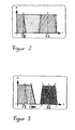
- a signal band S according to Figure 5a is generated.
- the signals U Bat , I Bat are each fed to a bandpass filter, preferably a low-pass filter 18, 18 ', the bandpass filter unit 2, so that according to Figure 5b, a filter band F results.
- a bandpass filter preferably a low-pass filter 18, 18 ', the bandpass filter unit 2
- a filter band F results.
- This can be modified by using a decimation filter, see Figure 5b.
- bandpass filtering and decimation filtering occur simultaneously. However, it can also be done one after the other.
Landscapes
- Physics & Mathematics (AREA)
- General Physics & Mathematics (AREA)
- Measurement Of Resistance Or Impedance (AREA)
- Secondary Cells (AREA)
Applications Claiming Priority (2)
| Application Number | Priority Date | Filing Date | Title |
|---|---|---|---|
| DE10347317 | 2003-10-08 | ||
| DE10347317A DE10347317A1 (de) | 2003-10-08 | 2003-10-08 | Einrichtung und Verfahren zur Bestimmung des Innenwiderstandes einer Batterie |
Publications (2)
| Publication Number | Publication Date |
|---|---|
| EP1522866A2 true EP1522866A2 (fr) | 2005-04-13 |
| EP1522866A3 EP1522866A3 (fr) | 2006-05-31 |
Family
ID=34306376
Family Applications (1)
| Application Number | Title | Priority Date | Filing Date |
|---|---|---|---|
| EP04023001A Ceased EP1522866A3 (fr) | 2003-10-08 | 2004-09-28 | Dispositif et procédé pour la détermination de la résistance interne d'une batterie |
Country Status (2)
| Country | Link |
|---|---|
| EP (1) | EP1522866A3 (fr) |
| DE (1) | DE10347317A1 (fr) |
Cited By (1)
| Publication number | Priority date | Publication date | Assignee | Title |
|---|---|---|---|---|
| WO2016030065A1 (fr) * | 2014-08-27 | 2016-03-03 | Robert Bosch Gmbh | Procédé de détermination de la résistance interne d'un accumulateur d'énergie électrique |
Families Citing this family (1)
| Publication number | Priority date | Publication date | Assignee | Title |
|---|---|---|---|---|
| DE102008053226B4 (de) * | 2008-10-25 | 2017-03-09 | Continental Automotive Gmbh | Verfahren zur Bewertung eines Körperschallsignals für ein Personenschutzsystem |
Family Cites Families (2)
| Publication number | Priority date | Publication date | Assignee | Title |
|---|---|---|---|---|
| US6262563B1 (en) * | 1998-09-11 | 2001-07-17 | Keith S. Champlin | Method and apparatus for measuring complex admittance of cells and batteries |
| DE10205120B4 (de) * | 2001-02-13 | 2004-12-16 | Akkumulatorenfabrik Moll Gmbh & Co. Kg | Verfahren und Vorrichtung zur Ermittlung des Innenwiderstandes einer Batterie, insbesondere einer Starterbatterie für ein Kraftfahrzeug |
-
2003
- 2003-10-08 DE DE10347317A patent/DE10347317A1/de not_active Withdrawn
-
2004
- 2004-09-28 EP EP04023001A patent/EP1522866A3/fr not_active Ceased
Cited By (3)
| Publication number | Priority date | Publication date | Assignee | Title |
|---|---|---|---|---|
| WO2016030065A1 (fr) * | 2014-08-27 | 2016-03-03 | Robert Bosch Gmbh | Procédé de détermination de la résistance interne d'un accumulateur d'énergie électrique |
| CN106796268A (zh) * | 2014-08-27 | 2017-05-31 | 罗伯特·博世有限公司 | 用于确定电蓄能器的内阻的方法 |
| US10288695B2 (en) | 2014-08-27 | 2019-05-14 | Robert Bosch Gmbh | Method for ascertaining an internal resistance of an electrical energy accumulator |
Also Published As
| Publication number | Publication date |
|---|---|
| DE10347317A1 (de) | 2005-05-12 |
| EP1522866A3 (fr) | 2006-05-31 |
Similar Documents
| Publication | Publication Date | Title |
|---|---|---|
| DE4203879A1 (de) | Verfahren zur umwandlung eines messsignals und eines referenzsignals in ein ausgangssignal, sowie konverter zur durchfuehrung des verfahrens | |
| EP0689054B1 (fr) | Procédé et dispositif pour la mesure du nombre de tours d'un moteur à courant continu avec une commutation mécanique | |
| DE102004047786A1 (de) | Verfahren zur Pulsationskorrektur innerhalb eines einen Medienmassenstrom messenden Messgeräts | |
| DE2800645B2 (de) | Schaltungsanordnung zum Erfassen und Umwandlen von analogdaten in digitale Daten | |
| EP0472877B1 (fr) | Dispositif pour déterminer la vitesse angulaire d'un moteur à combustion interne | |
| EP0847138A3 (fr) | Dispositif détecteur capacitif | |
| EP0271856A3 (fr) | Méthode et dispositif pour mésurer un paramètre | |
| DE4335303C2 (de) | Vorrichtung zum Messen von Oberflächenrauhigkeit | |
| DE4402072A1 (de) | Sensorkonditionierende Schaltungsanordnung zur Verwendung mit elektrisch erregten Meßwandlern | |
| EP1522866A2 (fr) | Dispositif et procédé pour la détermination de la résistance interne d'une batterie | |
| EP3123185B1 (fr) | Capteur de batterie électronique et procédé de détermination de la résistance interne d'une batterie | |
| DE102012220738A1 (de) | Messschaltung zum Bestimmen eines Widerstandswerts eines Sensorwider-standsbauelements | |
| DE19722077A1 (de) | Trägerfrequenzmeßverfahren | |
| DE69713457T2 (de) | Vorrichtung zur Berechnung der Fahrzeuggeschwindigkeit aus pulsierenden Komponenten im Signal des Generators | |
| WO2020160729A1 (fr) | Dispositif et procédé de réception et de traitement et d'émission de données de mesure synchronisées, et produit-programme informatique et utilisation | |
| DE10135674A1 (de) | Verfahren und Vorrichtung zur Auswertung von Meßsignalen | |
| DE3121611C2 (fr) | ||
| DE19531386A1 (de) | Auswerteschaltung für einen Dickfilm-Drucksensor | |
| DE4009383C2 (fr) | ||
| EP3948312B1 (fr) | Dispositif et procédé de détermination d'une tension de cellule électrique d'un élément de batterie d'une batterie de traction d'un véhicule | |
| WO1999056085A1 (fr) | Dispositif de mesure radiometrique de signaux emis par des detecteurs | |
| DE2612253A1 (de) | Verfahren und vorrichtung zur bestimmung des vulkanisationsverlaufs von kautschuk und die reaktionskinetische auswertung von vulkametrisch ermittelten vernetzungsisothermen | |
| DE4342868B4 (de) | Einrichtung zur Bestimmung des Gradienten eines Meßsignales | |
| DE3338193A1 (de) | Schaltungsanordnung zum messen der uebertragungsqualitaet eines digitalen pruefobjektes | |
| DE19700740C2 (de) | Verfahren zum Bestimmen der Frequenz eines sinusförmigen Signalabschnittes und Anordnung zum Ausführen dieses Verfahrens |
Legal Events
| Date | Code | Title | Description |
|---|---|---|---|
| PUAI | Public reference made under article 153(3) epc to a published international application that has entered the european phase |
Free format text: ORIGINAL CODE: 0009012 |
|
| AK | Designated contracting states |
Kind code of ref document: A2 Designated state(s): AT BE BG CH CY CZ DE DK EE ES FI FR GB GR HU IE IT LI LU MC NL PL PT RO SE SI SK TR |
|
| AX | Request for extension of the european patent |
Extension state: AL HR LT LV MK |
|
| RAP1 | Party data changed (applicant data changed or rights of an application transferred) |
Owner name: HELLA KGAA HUECK & CO. |
|
| PUAL | Search report despatched |
Free format text: ORIGINAL CODE: 0009013 |
|
| AK | Designated contracting states |
Kind code of ref document: A3 Designated state(s): AT BE BG CH CY CZ DE DK EE ES FI FR GB GR HU IE IT LI LU MC NL PL PT RO SE SI SK TR |
|
| AX | Request for extension of the european patent |
Extension state: AL HR LT LV MK |
|
| 17P | Request for examination filed |
Effective date: 20061123 |
|
| AKX | Designation fees paid |
Designated state(s): DE FR |
|
| 17Q | First examination report despatched |
Effective date: 20070220 |
|
| STAA | Information on the status of an ep patent application or granted ep patent |
Free format text: STATUS: THE APPLICATION HAS BEEN REFUSED |
|
| 18R | Application refused |
Effective date: 20100522 |