EP1522841B1 - System zur Erkennung von Fehlzündungen für einen Fahrzeugmotor - Google Patents
System zur Erkennung von Fehlzündungen für einen Fahrzeugmotor Download PDFInfo
- Publication number
- EP1522841B1 EP1522841B1 EP04292306A EP04292306A EP1522841B1 EP 1522841 B1 EP1522841 B1 EP 1522841B1 EP 04292306 A EP04292306 A EP 04292306A EP 04292306 A EP04292306 A EP 04292306A EP 1522841 B1 EP1522841 B1 EP 1522841B1
- Authority
- EP
- European Patent Office
- Prior art keywords
- data
- crankshaft
- detecting
- combustion failure
- engine
- Prior art date
- Legal status (The legal status is an assumption and is not a legal conclusion. Google has not performed a legal analysis and makes no representation as to the accuracy of the status listed.)
- Expired - Lifetime
Links
- 238000002485 combustion reaction Methods 0.000 title claims abstract description 29
- 230000001537 neural effect Effects 0.000 claims abstract description 24
- 238000005259 measurement Methods 0.000 claims abstract description 9
- 210000002569 neuron Anatomy 0.000 claims description 60
- 238000004364 calculation method Methods 0.000 claims description 9
- 238000001514 detection method Methods 0.000 claims description 7
- 239000007789 gas Substances 0.000 claims description 6
- 230000001133 acceleration Effects 0.000 claims description 5
- 238000012545 processing Methods 0.000 claims description 4
- 230000003068 static effect Effects 0.000 claims description 3
- 230000006870 function Effects 0.000 description 10
- 235000021183 entrée Nutrition 0.000 description 7
- 239000000523 sample Substances 0.000 description 7
- 238000004422 calculation algorithm Methods 0.000 description 4
- 230000013016 learning Effects 0.000 description 3
- 239000000446 fuel Substances 0.000 description 2
- 229930195733 hydrocarbon Natural products 0.000 description 2
- 150000002430 hydrocarbons Chemical class 0.000 description 2
- 230000004913 activation Effects 0.000 description 1
- 239000012298 atmosphere Substances 0.000 description 1
- 230000003197 catalytic effect Effects 0.000 description 1
- 239000000567 combustion gas Substances 0.000 description 1
- 230000006835 compression Effects 0.000 description 1
- 238000007906 compression Methods 0.000 description 1
- 230000006866 deterioration Effects 0.000 description 1
- 238000006073 displacement reaction Methods 0.000 description 1
- 239000003344 environmental pollutant Substances 0.000 description 1
- 238000004880 explosion Methods 0.000 description 1
- 239000003502 gasoline Substances 0.000 description 1
- 230000001939 inductive effect Effects 0.000 description 1
- 230000010365 information processing Effects 0.000 description 1
- 210000002364 input neuron Anatomy 0.000 description 1
- 230000009021 linear effect Effects 0.000 description 1
- 230000033001 locomotion Effects 0.000 description 1
- 238000003754 machining Methods 0.000 description 1
- 230000007246 mechanism Effects 0.000 description 1
- 230000015654 memory Effects 0.000 description 1
- 239000000203 mixture Substances 0.000 description 1
- 230000004048 modification Effects 0.000 description 1
- 238000012986 modification Methods 0.000 description 1
- 238000005457 optimization Methods 0.000 description 1
- 210000004205 output neuron Anatomy 0.000 description 1
- 230000001105 regulatory effect Effects 0.000 description 1
- 230000004044 response Effects 0.000 description 1
Images
Classifications
-
- G—PHYSICS
- G01—MEASURING; TESTING
- G01M—TESTING STATIC OR DYNAMIC BALANCE OF MACHINES OR STRUCTURES; TESTING OF STRUCTURES OR APPARATUS, NOT OTHERWISE PROVIDED FOR
- G01M15/00—Testing of engines
- G01M15/04—Testing internal-combustion engines
- G01M15/11—Testing internal-combustion engines by detecting misfire
-
- F—MECHANICAL ENGINEERING; LIGHTING; HEATING; WEAPONS; BLASTING
- F02—COMBUSTION ENGINES; HOT-GAS OR COMBUSTION-PRODUCT ENGINE PLANTS
- F02B—INTERNAL-COMBUSTION PISTON ENGINES; COMBUSTION ENGINES IN GENERAL
- F02B77/00—Component parts, details or accessories, not otherwise provided for
- F02B77/08—Safety, indicating, or supervising devices
- F02B77/085—Safety, indicating, or supervising devices with sensors measuring combustion processes, e.g. knocking, pressure, ionization, combustion flame
- F02B77/086—Sensor arrangements in the exhaust, e.g. for temperature, misfire, air/fuel ratio, oxygen sensors
-
- F—MECHANICAL ENGINEERING; LIGHTING; HEATING; WEAPONS; BLASTING
- F02—COMBUSTION ENGINES; HOT-GAS OR COMBUSTION-PRODUCT ENGINE PLANTS
- F02D—CONTROLLING COMBUSTION ENGINES
- F02D41/00—Electrical control of supply of combustible mixture or its constituents
- F02D41/0097—Electrical control of supply of combustible mixture or its constituents using means for generating speed signals
-
- F—MECHANICAL ENGINEERING; LIGHTING; HEATING; WEAPONS; BLASTING
- F02—COMBUSTION ENGINES; HOT-GAS OR COMBUSTION-PRODUCT ENGINE PLANTS
- F02D—CONTROLLING COMBUSTION ENGINES
- F02D41/00—Electrical control of supply of combustible mixture or its constituents
- F02D41/02—Circuit arrangements for generating control signals
- F02D41/14—Introducing closed-loop corrections
- F02D41/1401—Introducing closed-loop corrections characterised by the control or regulation method
- F02D41/1405—Neural network control
-
- F—MECHANICAL ENGINEERING; LIGHTING; HEATING; WEAPONS; BLASTING
- F02—COMBUSTION ENGINES; HOT-GAS OR COMBUSTION-PRODUCT ENGINE PLANTS
- F02D—CONTROLLING COMBUSTION ENGINES
- F02D2200/00—Input parameters for engine control
- F02D2200/02—Input parameters for engine control the parameters being related to the engine
- F02D2200/04—Engine intake system parameters
- F02D2200/0406—Intake manifold pressure
-
- F—MECHANICAL ENGINEERING; LIGHTING; HEATING; WEAPONS; BLASTING
- F02—COMBUSTION ENGINES; HOT-GAS OR COMBUSTION-PRODUCT ENGINE PLANTS
- F02D—CONTROLLING COMBUSTION ENGINES
- F02D2200/00—Input parameters for engine control
- F02D2200/02—Input parameters for engine control the parameters being related to the engine
- F02D2200/10—Parameters related to the engine output, e.g. engine torque or engine speed
- F02D2200/1002—Output torque
-
- F—MECHANICAL ENGINEERING; LIGHTING; HEATING; WEAPONS; BLASTING
- F02—COMBUSTION ENGINES; HOT-GAS OR COMBUSTION-PRODUCT ENGINE PLANTS
- F02D—CONTROLLING COMBUSTION ENGINES
- F02D2200/00—Input parameters for engine control
- F02D2200/02—Input parameters for engine control the parameters being related to the engine
- F02D2200/10—Parameters related to the engine output, e.g. engine torque or engine speed
- F02D2200/1015—Engines misfires
Definitions
- the present invention relates to a system for detecting a misfire of a combustion engine of a motor vehicle.
- hydrocarbons considered as pollutants and whose emissions are regulated, are emitted in excess into the atmosphere.
- anti-pollution legislation requires the detection of misfires and the modification of engine operation control parameters when their number exceeds predefined thresholds.
- the system includes a neural processor executing a reconfigurable network topology comprising a plurality of hidden layers containing interconnected neurons in a recursive configuration.
- the object of the invention is to propose an alternative system for detecting a misfire.
- Such a system is simple and makes it possible to detect a misfire with a relatively short calculation time.
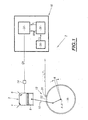
- Figure 1 shows schematically a system 2 for detecting a misfire of a cylinder 3 of a motor vehicle engine.
- This cylinder 3 comprises an exhaust valve 4 of the residual combustion gases and an intake valve 6 of air and fuel. It contains a piston 8 movable, sliding by reciprocating movement, during the phases of engine operation. This piston 8 is connected by an articulated link mechanism 10 to a crankshaft schematized by its main axis AA.
- the four operating times of a four-stroke internal combustion engine include a phase of admission of air and fuel, a phase of air compression and ignition of the mixture for example to the using a spark plug in the case of a spark ignition engine, a phase of explosion and expansion of the burnt gases and a phase of exhaust gas residual combustion.
- each cylinder 3 drives the crankshaft in rotation during its expansion phase and is driven by the other cylinders during the other phases.
- the piston 8 of the cylinder 3 is able to move from a position called top dead center TDC to a position called low dead point PMB and to drive the crankshaft in rotation by half a turn around. its axis AA.
- the detection system 2 is able to detect a misfire produced during the expansion phase of a cylinder 3 of a motor by detecting a drop in the indicated torque transmitted by the piston.
- the indicated torque of a cylinder of an engine is defined as the mechanical torque produced on the crankshaft by the pressure generated during combustion.
- the detection system 2 comprises a measuring sensor 14 of the engine load CH, acquisition means 12 of the crankshaft speed and a multifunction computer 16 of the engine.
- the measurement sensor 14 of the load CH of the engine is located at the confluence of the intake manifolds of the cylinders 3 of the engine. It is able to measure the pressure of the air admitted into the cylinder 3.
- the crankshaft speed information acquisition means 12 comprise a sensor for measuring the angular position of the crankshaft. This sensor is formed in the example described by a coded wheel 18 and a corresponding probe 20.
- the coded wheel 18 is integral with the crankshaft. It can for example be fixed to the flywheel. This wheel comprises for example fifty eight teeth arranged radially at its periphery at predefined angles ⁇ of 6 degrees and a location 22 where two teeth are missing to establish a reference point with respect to the position of the top dead center TDC of each piston of the cylinders.
- the probe 20 is for example an inductive type probe. It is fixed close to and facing the teeth of the wheel 18 so as to detect their passages. During the rotation of the crankshaft and the coded wheel, the probe 20 is able to generate a signal transformable into slots. The duration between two edges of the generated slots is equal to the passage time of each angular segment in front of the probe.
- the multifunction computer 16 of the engine comprises, in particular, calculating means 26, 28 for the average speed of rotation of the engine, determining means 26, 28 for information representative of the indicated torque of the engine cylinder and neural means 30.
- the means for calculating the average rotation speed of the motor comprise an internal clock 26 and a calculation unit 28.
- the internal clock 26 is able to receive the signal in the form of a slot emitted by the probe 20 and to measure the duration of each slot. During a relaxation phase, the clock is able to measure the n elementary values of duration T i each corresponding to a displacement of the crankshaft of the predefined angle ⁇ .
- the average rotational speed of the RPM engine is defined as the average rotational speed of the crankshaft. It is calculated during a relaxation phase of the cylinder 3 corresponding to a half-turn stroke of the crankshaft.
- Each elementary information of speed fluctuation F i is defined as the difference between a rotational speed of the crankshaft on a stroke corresponding to an angle ⁇ and an average speed T moy of the crankshaft averaged over a stroke corresponding to a half-turn of rotation of the crankshaft. crankshaft.
- the clock 26 is able to measure thirty values of duration T i corresponding to the passage of thirty teeth of the coded wheel 18, that is to say alternately thirty teeth or twenty-eight teeth and the two missing teeth according to the angular segment used for the measurement.
- the duration of passage of the missing teeth is estimated using the durations measured during the passage of the preceding and following teeth.
- the means for determining information representative of the indicated torque comprise an accelerometer integral with the engine block.
- This accelerometer is capable of delivering n elementary acceleration information measured during the rotation of the crankshaft over a half-rotation stroke of the crankshaft.
- the information determining means representative of the indicated torque comprise an exhaust gas pressure sensor of the cylinder 3 of the engine and the calculation unit 28.
- the pressure sensor is fixed at the outlet of the pipes of the engine. exhaust and is able to generate n information on the exhaust gas exhaust pressure.
- the calculation unit 28 is able to calculate n elementary information of variation exhaust pressure. Each elementary variation information is calculated from the difference between an exhaust pressure on a stroke corresponding to an angle ⁇ and a pressure averaged over a stroke corresponding to a half-turn of rotation of the crankshaft.
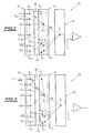
- the neural means 30 are formed by a network as shown in Figure 2.
- This network is static and is composed of basic processing elements called neurons S e1 , ..., S e30 .
- the neurons are arranged in an input layer 32, a single hidden layer 34 and an output layer 36.
- Each neuron of a layer is associated with each neuron of another layer via weight w ij .
- the output of a neuron is a linear combination of the neurons that are connected to this neuron and all the weights w ij of these connections.
- the input layer 32 and the hidden layer 34 are composed of a first 38 and a second 40 stages.
- the first stage 38 of the input layer 32 comprises thirty neurons S e1 ,..., S e30 which receive as input signals corresponding to the information representative of the indicated torque of the engine cylinder.
- this information comprises n elementary speed fluctuation information F i of the crankshaft for i ranging from 1 to 30.
- the second stage 40 of the input layer 32 comprises two neurons S e31 , S e32 which receive as input signals respectively corresponding to the average speed information RPM of the engine and the engine load CH.
- the first 38 and the second 40 stages are independent of each other.
- the weights w ij associated with the relations between the neurons S e1 , S e2 , .. S e30 of the input layer 32 of the first stage 38 and the neurons S c3 , S c4 , S c5 , S c6 of the hidden layer 34 second stage 40 are zero.
- the weights associated with the relationships between the neurons S e31 , S e32 of the input layer 32 of the second stage 40 and the neurons S c1 , S c2 of the hidden layer 34 of the first stage 38 are zero.
- the neuron S f of the output layer 36 delivers an output signal between 0 and 1. This signal is compared in a comparator to a threshold value Vs to indicate in case of exceeding the existence of a misfire.
- This threshold value is for example equal to 0.5.
- the weights w ij and W i of the neurons are obtained in a conventional manner during a learning phase from a load-stabilized heuristic set of the engine CH and at the average speed of the motor RPM. They are calculated during the learning phase by an optimization algorithm quasi Newton type or Levenberg Marquardt type.
- the weights W ij and W i are recorded in a non-volatile memory of ROM type not shown of the multifunction computer of the engine 16 and represent the calibration data of the algorithm.
- the detection system 2 of a misfire also includes a cylinder phasing sensor not shown motor. This sensor is capable of sending to the multifunction computer of the engine 16 identification information of the cylinder in the expansion phase. The computing unit 28 is able to correlate this information with the information indicating the existence of a misfire emitted by the neural means 30 to identify the cylinder that has generated a misfire.
- a plurality of neurons may be disposed in the first stage 38 of the hidden layer.
- neurons may be arranged in the second stage 40 of the hidden layer.
- the output layer 36 includes a bias.
- FIG. 3 represents a second exemplary structure of the neural means 30 according to the invention.
- the input layer 32 of the first stage 38 comprises an additional neuron S e0 which receives as input an inverse signal of the average speed of the motor 1 / RPM whose sign is variable as a function of the position of the coded wheel. basically say according to the angular segment used for the measurement.
- the neuron S e0 makes it possible to compensate for the asymmetries generated by the machining tolerances of the teeth of coded wheel 18 and by its off-centering.
- another additional neuron S e0 receives as input an inverse signal of the average engine speed squared 1 / RPM 2 whose sign is variable as a function of the position of the coded wheel.
- the wheel 18 of the angular position measuring sensor 12 comprises a different number of teeth and defines a different number of elementary acceleration information F i .
- the first stage 38 of the input layer 32 of the neural means 30 comprises a different number of neurons.
- angular segment ie not covering a single tooth, but several, and may be for example equal to 12 ° or 18 °, etc ....
- the skilled person will adjust the size of the angular sector to reduce the number of neurons of the input layer in order to simplify the calculations while keeping a good accuracy of the algorithm.
- a computer dedicated to the function can be used in place of the multifunction computer of the engine 16.
- the detection system of a misfire according to the invention can be used for engines of different types with internal combustion and in particular for gasoline or diesel engines, for four- or six-cylinder engines.
- the weights of the neurons vary from one vehicle to another and it is necessary to determine them by learning for a given engine and for a given range of vehicles.
Landscapes
- Engineering & Computer Science (AREA)
- Chemical & Material Sciences (AREA)
- Combustion & Propulsion (AREA)
- General Engineering & Computer Science (AREA)
- Mechanical Engineering (AREA)
- Evolutionary Computation (AREA)
- Artificial Intelligence (AREA)
- Physics & Mathematics (AREA)
- General Physics & Mathematics (AREA)
- Combined Controls Of Internal Combustion Engines (AREA)
- Testing Of Engines (AREA)
- Ignition Installations For Internal Combustion Engines (AREA)
- Air-Conditioning For Vehicles (AREA)
Claims (12)
- Anlage (2) zum Erfassen einer Fehlverbrennung wenigstens eines Zylinders (3) einer Brennkraftmaschine eines Kraftfahrzeugs mit:- Einrichtungen (14) zum Gewinnen von Information über die Maschinenlast,- Einrichtungen (12, 18, 20) zum Gewinnen von Informationen über die Geschwindigkeit der Kurbelwelle,- Einrichtungen (28) zum Berechnen des mittleren Drehzahlbereiches der Maschine aus den Informationen über die Geschwindigkeit der Kurbelwelle,- Einrichtungen (26, 28) zum Gewinnen von Informationen, die ein bestimmtes Moment des Zylinders der Maschine wiedergeben,- Neuroeinrichtungen (30) zum Verarbeiten der Informationen über die Maschinenlast, der Informationen, die ein bestimmtes Moment wiedergeben und der Informationen über den mittleren Drehzahlbereich der Maschine, um eine Fehlverbrennung zu erfassen, dadurch gekennzeichnet, dass:- die Einrichtungen zum Gewinnen von Informationen, die ein bestimmtes Moment wiedergeben, so ausgebildet sind, dass sie n Grundinformationen, die das bestimmte Moment wiedergeben, entsprechend n aufeinander folgenden Messschritten des bestimmten Momentes liefern können, die während einer Verbrennung in einem Zylinder vorgenommen werden, und dass- die Neuroeinrichtungen eine erste Neurostufe (38) und eine zweite Neurostufe (40) umfassen, die voneinander unabhängig sind, wobei die erste Stufe (38) am Eingang die n Grundinformationen empfängt, die das bestimmte Moment wiedergeben, und die zweite Stufe (40) am Eingang die Informationen über die Maschinenlast und den mittleren Drehzahlbereich der Maschine empfangen, um die Verarbeitung der Informationen und die Erfassung einer Fehlverbrennung zu optimieren.
- Anlage zum Erfassen einer Fehlverbrennung nach Anspruch 1, dadurch gekennzeichnet, dass die Einrichtungen (26, 28) zum Gewinnen von Informationen, die ein bestimmtes Moment wiedergeben, Einrichtungen (28) zum Berechnen von Informationen über die Schwankung der Geschwindigkeit umfassen und dass die n Grundinformationen n Informationen über die Schwankung der Geschwindigkeit umfassen, wobei eine Information über die Schwankung der Geschwindigkeit ausgehend vom Unterschied zwischen einer Geschwindigkeit der Kurbelwelle während eines vorgegebenen Drehweges der Kurbelwelle und einer mittleren Geschwindigkeit der Kurbelwelle während eines Weges berechnet wird, der einer halben Umdrehung der Kurbelwelle entspricht.
- Anlage zum Erfassen einer Fehlverbrennung nach Anspruch 1, dadurch gekennzeichnet, dass die Einrichtung (26, 28) zum Gewinnen von Informationen, die ein bestimmtes Moment wiedergeben, einen Beschleunigungsmesser umfassen und dass die n Grundinformationen n Beschleunigungsinformationen umfassen, die während der Drehung der Kurbelwelle über einen bestimmten Weg gemessen werden.
- Anlage zum Erfassen einer Fehlverbrennungen nach Anspruch 1, dadurch gekennzeichnet, dass die Einrichtung (26, 28) zum Gewinnen von Informationen, die ein bestimmtes Moment wiedergeben, einen Messfühler für den Druck des Abgases des Zylinders der Maschine umfassen und dass die n Grundinformationen n Informationen über die Änderung des Druckes umfassen, wobei eine Information über die Änderung des Druckes ausgehend von dem Unterschied zwischen einem Druck des Abgases während eines bestimmten Drehweges der Kurbelwelle und einem mittleren Druck des Abgases während eines Weges berechnet wird, der einer halben Umdrehung der Kurbelwelle entspricht.
- Anlage zum Erfassen einer Fehlverbrennung nach einem der vorhergehenden Ansprüche, dadurch gekennzeichnet, dass die Einrichtungen (12) zum Gewinnen von Informationen über die Geschwindigkeit der Kurbelwelle Einrichtungen zum Gewinnen von Informationen über die Winkelposition der Kurbelwelle umfassen.
- Anlage zum Erfassen einer Fehlverbrennung nach Anspruch 5, dadurch gekennzeichnet, dass die Einrichtungen (12) zum Gewinnen von Informationen über die Geschwindigkeit und die Winkelposition der Kurbelwelle ein Kodierungsrad (18), das mit der Kurbelwelle verbunden ist, und eine entsprechende Sonde (20) umfassen.
- Anlage zum Erfassen einer Fehlverbrennung nach einer der vorhergehenden Ansprüche, dadurch gekennzeichnet, dass die Neuroeinrichtungen (30) aus einem Satz (32) von Eingangsneuronen, einem einzigen Satz (34) von verdeckten Neuronen und einem Satz (36) von Ausgangsneuronen gebildet sind.
- Anlage zum Erfassen einer Fehlverbrennung nach Anspruch 7, dadurch gekennzeichnet, dass die erste Stufe (38) und die zweite Stufe (40) jeweils Neuronen des Eingangssatzes (32) und des verdeckten Satzes (34) umfassen.
- Anlage zum Erfassen einer Fehlverbrennung nach einem der vorhergehenden Ansprüche, dadurch gekennzeichnet, dass die Neuroeinrichtungen (30) statisch sind.
- Anlage zum Erfassen einer Fehlverbrennung nach einem der Ansprüche 7 bis 9 in Kombination mit Anspruch 6, dadurch gekennzeichnet, dass die erste Stufe (38) am Eingang zusätzlich ein zum mittleren Drehzahlbereich der Maschine umgekehrtes Signal (1/RPM) empfängt, dessen Vorzeichen in Abhängigkeit von dem Winkelsegment des Kodierungsrades variiert, das zur Durchführung der Messung verwandt wird, um die Dissymmetrie zu korrigieren.
- Anlage zum Erfassen einer Fehlverbrennung nach einem der Ansprüche 7 bis 9 in Kombination mit Anspruch 6, dadurch gekennzeichnet, dass die erste Stufe (38) am Eingang zusätzlich ein zum mittleren Drehzahlbereich der Maschine im Quadrat umgekehrtes Signal (1/RPM2) empfängt, dessen Vorzeichen in Abhängigkeit vom Winkelsegment des Kodierungsrades variiert, das zu Durchführung der Messung verwandt wird, um die Dissymmetrie zu korrigieren.
- Anlage zum Erfassen einer Fehlverbrennung nach einem der vorhergehenden Ansprüche dadurch gekennzeichnet, dass die Neuroeinrichtungen (30) und die Einrichtungen (28) zum Berechnen in einen Multifunktionsrechner (16) der Maschine eingebaut sind.
Applications Claiming Priority (2)
| Application Number | Priority Date | Filing Date | Title |
|---|---|---|---|
| FR0311732A FR2860549B1 (fr) | 2003-10-07 | 2003-10-07 | Systeme de detection d'un rate de combustion pour un moteur de vehicule automobile |
| FR0311732 | 2003-10-07 |
Publications (2)
| Publication Number | Publication Date |
|---|---|
| EP1522841A1 EP1522841A1 (de) | 2005-04-13 |
| EP1522841B1 true EP1522841B1 (de) | 2006-12-27 |
Family
ID=34307496
Family Applications (1)
| Application Number | Title | Priority Date | Filing Date |
|---|---|---|---|
| EP04292306A Expired - Lifetime EP1522841B1 (de) | 2003-10-07 | 2004-09-27 | System zur Erkennung von Fehlzündungen für einen Fahrzeugmotor |
Country Status (5)
| Country | Link |
|---|---|
| EP (1) | EP1522841B1 (de) |
| AT (1) | ATE349688T1 (de) |
| DE (1) | DE602004003876T2 (de) |
| ES (1) | ES2280014T3 (de) |
| FR (1) | FR2860549B1 (de) |
Families Citing this family (1)
| Publication number | Priority date | Publication date | Assignee | Title |
|---|---|---|---|---|
| CN116220903B (zh) * | 2023-02-02 | 2024-04-19 | 重庆赛力斯新能源汽车设计院有限公司 | 一种发动机失火故障诊断方法、装置、服务端及存储介质 |
Family Cites Families (4)
| Publication number | Priority date | Publication date | Assignee | Title |
|---|---|---|---|---|
| US5699253A (en) * | 1995-04-05 | 1997-12-16 | Ford Global Technologies, Inc. | Nonlinear dynamic transform for correction of crankshaft acceleration having torsional oscillations |
| US6434541B1 (en) * | 1996-10-23 | 2002-08-13 | Ford Global Technologies, Inc. | Automotive engine misfire detection system including a bit-serial based recurrent neuroprocessor |
| US5732382A (en) * | 1996-11-06 | 1998-03-24 | Ford Global Technologies, Inc. | Method for identifying misfire events of an internal combustion engine |
| US6292738B1 (en) * | 2000-01-19 | 2001-09-18 | Ford Global Tech., Inc. | Method for adaptive detection of engine misfire |
-
2003
- 2003-10-07 FR FR0311732A patent/FR2860549B1/fr not_active Expired - Fee Related
-
2004
- 2004-09-27 DE DE602004003876T patent/DE602004003876T2/de not_active Expired - Lifetime
- 2004-09-27 ES ES04292306T patent/ES2280014T3/es not_active Expired - Lifetime
- 2004-09-27 EP EP04292306A patent/EP1522841B1/de not_active Expired - Lifetime
- 2004-09-27 AT AT04292306T patent/ATE349688T1/de not_active IP Right Cessation
Also Published As
| Publication number | Publication date |
|---|---|
| DE602004003876D1 (de) | 2007-02-08 |
| ATE349688T1 (de) | 2007-01-15 |
| EP1522841A1 (de) | 2005-04-13 |
| DE602004003876T2 (de) | 2007-10-11 |
| FR2860549A1 (fr) | 2005-04-08 |
| ES2280014T3 (es) | 2007-09-01 |
| FR2860549B1 (fr) | 2006-01-27 |
Similar Documents
| Publication | Publication Date | Title |
|---|---|---|
| EP0647774B1 (de) | System zur Erfassung und Sofortverarbeitung von Daten für eine Steurerung einer Brennkraftmaschine | |
| EP1548418B1 (de) | Vorrichtung zur Kalibrierung einer Druck-Messkette in einem Zylinder eines Kraftfahrzeugdieselmotors | |
| EP0716298B1 (de) | Erkennen von Verbrennungsaussetzern in inneren Verbrennungsmotoren | |
| FR2689934A1 (fr) | Procédé et dispositif de détection des irrégularités de combustion d'un moteur en particulier à moyen et haut régimes, application à un système de contrôle d'un moteur à injection. | |
| EP2232035B1 (de) | VERFAHREN ZUR ERZEUGUNG EINES SYNCHRONISATIONSSIGNALS FÜR eine Brennkraftmaschine | |
| EP0774110B1 (de) | Verfahren und vorrichtung zum erkennen von verbrennungsaussetzern einer brennkraftmaschine mit funkenzündung | |
| EP0678156B1 (de) | Verfahren und vorrichtung zur detektion der fehlzündungen einer brennkraftmaschine mit funkenzündung | |
| EP1522841B1 (de) | System zur Erkennung von Fehlzündungen für einen Fahrzeugmotor | |
| EP0522908B1 (de) | Verfahren und System um die Luftmenge in einem Zylinder einer Brennkraftmaschine zuzurechnen | |
| FR2507250A1 (fr) | Dispositif pour mesurer la position angulaire du vilebrequin d'un moteur a combustion interne | |
| EP0029374B1 (de) | Signal-generator zur Korrektur der Einstellung der Frühzündung in Abhängigkeit vom Klopfverhalten | |
| WO1998029718A1 (fr) | Procede de calcul du couple d'un moteur thermique a injection commandee electroniquement | |
| FR2919678A1 (fr) | Procede et dispositif pour diagnostiquer une fuite d'injecteur dans un moteur a combustion interne | |
| GB2301898A (en) | Detecting engine cylinder misfire | |
| EP2641073B1 (de) | Verfahren zur erkennung von verbrennungsdefekten bei einem verbrennungsmotor | |
| EP1607605B1 (de) | System zum Abschätzen des Drucks im Abgaskrümmer einer Dieselbrennkraftmaschine und Verfahren zur Systemkalibrierung | |
| FR2768179A1 (fr) | Procede de detection d'une perturbation anormale du couple d'un moteur a combustion interne | |
| KR102119865B1 (ko) | 단기통 4행정 엔진의 실화 진단 방법 및 장치 | |
| EP1217354B1 (de) | Verfahren zur Auswertung des Drehmomentes eines Brennkraftmotors | |
| KR102119852B1 (ko) | 단기통 4행정 엔진의 실화 진단 방법 및 장치 | |
| FR2936015A1 (fr) | Estimation de variables d'etat d'un moteur a combustion interne. | |
| EP0592134A2 (de) | Komplementäres Verfahren zum Erkennen von Verbrennungsaussetzern in inneren Verbrennungsmotoren | |
| EP0732573A2 (de) | Verfahren und Vorrichtung zur Erkennung von Vibrationssignalen, z.B. dem Klopfen eines internen Verbrennungsmotors | |
| FR2757632A1 (fr) | Procede de detection d'une perturbation anormale du couple mesure d'un moteur thermique | |
| FR2754852A1 (fr) | Procede de synchronisation du systeme electronique de commande de moteur a combustion interne |
Legal Events
| Date | Code | Title | Description |
|---|---|---|---|
| PUAI | Public reference made under article 153(3) epc to a published international application that has entered the european phase |
Free format text: ORIGINAL CODE: 0009012 |
|
| AK | Designated contracting states |
Kind code of ref document: A1 Designated state(s): AT BE BG CH CY CZ DE DK EE ES FI FR GB GR HU IE IT LI LU MC NL PL PT RO SE SI SK TR |
|
| AX | Request for extension of the european patent |
Extension state: AL HR LT LV MK |
|
| 17P | Request for examination filed |
Effective date: 20050921 |
|
| AKX | Designation fees paid |
Designated state(s): AT BE BG CH CY CZ DE DK EE ES FI FR GB GR HU IE IT LI LU MC NL PL PT RO SE SI SK TR |
|
| GRAP | Despatch of communication of intention to grant a patent |
Free format text: ORIGINAL CODE: EPIDOSNIGR1 |
|
| GRAS | Grant fee paid |
Free format text: ORIGINAL CODE: EPIDOSNIGR3 |
|
| GRAA | (expected) grant |
Free format text: ORIGINAL CODE: 0009210 |
|
| AK | Designated contracting states |
Kind code of ref document: B1 Designated state(s): AT BE BG CH CY CZ DE DK EE ES FI FR GB GR HU IE IT LI LU MC NL PL PT RO SE SI SK TR |
|
| PG25 | Lapsed in a contracting state [announced via postgrant information from national office to epo] |
Ref country code: IE Free format text: LAPSE BECAUSE OF FAILURE TO SUBMIT A TRANSLATION OF THE DESCRIPTION OR TO PAY THE FEE WITHIN THE PRESCRIBED TIME-LIMIT Effective date: 20061227 Ref country code: SK Free format text: LAPSE BECAUSE OF FAILURE TO SUBMIT A TRANSLATION OF THE DESCRIPTION OR TO PAY THE FEE WITHIN THE PRESCRIBED TIME-LIMIT Effective date: 20061227 Ref country code: CZ Free format text: LAPSE BECAUSE OF FAILURE TO SUBMIT A TRANSLATION OF THE DESCRIPTION OR TO PAY THE FEE WITHIN THE PRESCRIBED TIME-LIMIT Effective date: 20061227 Ref country code: AT Free format text: LAPSE BECAUSE OF FAILURE TO SUBMIT A TRANSLATION OF THE DESCRIPTION OR TO PAY THE FEE WITHIN THE PRESCRIBED TIME-LIMIT Effective date: 20061227 Ref country code: SI Free format text: LAPSE BECAUSE OF FAILURE TO SUBMIT A TRANSLATION OF THE DESCRIPTION OR TO PAY THE FEE WITHIN THE PRESCRIBED TIME-LIMIT Effective date: 20061227 Ref country code: DK Free format text: LAPSE BECAUSE OF FAILURE TO SUBMIT A TRANSLATION OF THE DESCRIPTION OR TO PAY THE FEE WITHIN THE PRESCRIBED TIME-LIMIT Effective date: 20061227 Ref country code: FI Free format text: LAPSE BECAUSE OF FAILURE TO SUBMIT A TRANSLATION OF THE DESCRIPTION OR TO PAY THE FEE WITHIN THE PRESCRIBED TIME-LIMIT Effective date: 20061227 Ref country code: NL Free format text: LAPSE BECAUSE OF FAILURE TO SUBMIT A TRANSLATION OF THE DESCRIPTION OR TO PAY THE FEE WITHIN THE PRESCRIBED TIME-LIMIT Effective date: 20061227 Ref country code: PL Free format text: LAPSE BECAUSE OF FAILURE TO SUBMIT A TRANSLATION OF THE DESCRIPTION OR TO PAY THE FEE WITHIN THE PRESCRIBED TIME-LIMIT Effective date: 20061227 Ref country code: RO Free format text: LAPSE BECAUSE OF FAILURE TO SUBMIT A TRANSLATION OF THE DESCRIPTION OR TO PAY THE FEE WITHIN THE PRESCRIBED TIME-LIMIT Effective date: 20061227 |
|
| REG | Reference to a national code |
Ref country code: GB Ref legal event code: FG4D Free format text: NOT ENGLISH |
|
| REG | Reference to a national code |
Ref country code: IE Ref legal event code: FG4D Free format text: LANGUAGE OF EP DOCUMENT: FRENCH |
|
| REF | Corresponds to: |
Ref document number: 602004003876 Country of ref document: DE Date of ref document: 20070208 Kind code of ref document: P |
|
| GBT | Gb: translation of ep patent filed (gb section 77(6)(a)/1977) |
Effective date: 20070228 |
|
| PG25 | Lapsed in a contracting state [announced via postgrant information from national office to epo] |
Ref country code: BG Free format text: LAPSE BECAUSE OF FAILURE TO SUBMIT A TRANSLATION OF THE DESCRIPTION OR TO PAY THE FEE WITHIN THE PRESCRIBED TIME-LIMIT Effective date: 20070327 Ref country code: SE Free format text: LAPSE BECAUSE OF FAILURE TO SUBMIT A TRANSLATION OF THE DESCRIPTION OR TO PAY THE FEE WITHIN THE PRESCRIBED TIME-LIMIT Effective date: 20070327 |
|
| PG25 | Lapsed in a contracting state [announced via postgrant information from national office to epo] |
Ref country code: PT Free format text: LAPSE BECAUSE OF FAILURE TO SUBMIT A TRANSLATION OF THE DESCRIPTION OR TO PAY THE FEE WITHIN THE PRESCRIBED TIME-LIMIT Effective date: 20070528 |
|
| NLV1 | Nl: lapsed or annulled due to failure to fulfill the requirements of art. 29p and 29m of the patents act | ||
| REG | Reference to a national code |
Ref country code: ES Ref legal event code: FG2A Ref document number: 2280014 Country of ref document: ES Kind code of ref document: T3 |
|
| PLBE | No opposition filed within time limit |
Free format text: ORIGINAL CODE: 0009261 |
|
| STAA | Information on the status of an ep patent application or granted ep patent |
Free format text: STATUS: NO OPPOSITION FILED WITHIN TIME LIMIT |
|
| 26N | No opposition filed |
Effective date: 20070928 |
|
| BERE | Be: lapsed |
Owner name: PEUGEOT CITROEN AUTOMOBILES S.A. Effective date: 20070930 |
|
| PG25 | Lapsed in a contracting state [announced via postgrant information from national office to epo] |
Ref country code: GR Free format text: LAPSE BECAUSE OF FAILURE TO SUBMIT A TRANSLATION OF THE DESCRIPTION OR TO PAY THE FEE WITHIN THE PRESCRIBED TIME-LIMIT Effective date: 20070328 Ref country code: MC Free format text: LAPSE BECAUSE OF NON-PAYMENT OF DUE FEES Effective date: 20070930 |
|
| PG25 | Lapsed in a contracting state [announced via postgrant information from national office to epo] |
Ref country code: BE Free format text: LAPSE BECAUSE OF NON-PAYMENT OF DUE FEES Effective date: 20070930 |
|
| PG25 | Lapsed in a contracting state [announced via postgrant information from national office to epo] |
Ref country code: EE Free format text: LAPSE BECAUSE OF FAILURE TO SUBMIT A TRANSLATION OF THE DESCRIPTION OR TO PAY THE FEE WITHIN THE PRESCRIBED TIME-LIMIT Effective date: 20061227 |
|
| REG | Reference to a national code |
Ref country code: CH Ref legal event code: PL |
|
| PG25 | Lapsed in a contracting state [announced via postgrant information from national office to epo] |
Ref country code: LI Free format text: LAPSE BECAUSE OF NON-PAYMENT OF DUE FEES Effective date: 20070930 Ref country code: CH Free format text: LAPSE BECAUSE OF NON-PAYMENT OF DUE FEES Effective date: 20070930 |
|
| PG25 | Lapsed in a contracting state [announced via postgrant information from national office to epo] |
Ref country code: CY Free format text: LAPSE BECAUSE OF FAILURE TO SUBMIT A TRANSLATION OF THE DESCRIPTION OR TO PAY THE FEE WITHIN THE PRESCRIBED TIME-LIMIT Effective date: 20061227 Ref country code: LU Free format text: LAPSE BECAUSE OF NON-PAYMENT OF DUE FEES Effective date: 20070927 |
|
| PG25 | Lapsed in a contracting state [announced via postgrant information from national office to epo] |
Ref country code: HU Free format text: LAPSE BECAUSE OF FAILURE TO SUBMIT A TRANSLATION OF THE DESCRIPTION OR TO PAY THE FEE WITHIN THE PRESCRIBED TIME-LIMIT Effective date: 20070628 Ref country code: TR Free format text: LAPSE BECAUSE OF FAILURE TO SUBMIT A TRANSLATION OF THE DESCRIPTION OR TO PAY THE FEE WITHIN THE PRESCRIBED TIME-LIMIT Effective date: 20061227 |
|
| PG25 | Lapsed in a contracting state [announced via postgrant information from national office to epo] |
Ref country code: CH Free format text: LAPSE BECAUSE OF NON-PAYMENT OF DUE FEES Effective date: 20080930 Ref country code: LI Free format text: LAPSE BECAUSE OF NON-PAYMENT OF DUE FEES Effective date: 20080930 |
|
| REG | Reference to a national code |
Ref country code: ES Ref legal event code: GC2A Effective date: 20110202 |
|
| PGFP | Annual fee paid to national office [announced via postgrant information from national office to epo] |
Ref country code: GB Payment date: 20110830 Year of fee payment: 8 |
|
| GBPC | Gb: european patent ceased through non-payment of renewal fee |
Effective date: 20120927 |
|
| PG25 | Lapsed in a contracting state [announced via postgrant information from national office to epo] |
Ref country code: GB Free format text: LAPSE BECAUSE OF NON-PAYMENT OF DUE FEES Effective date: 20120927 |
|
| REG | Reference to a national code |
Ref country code: DE Ref legal event code: R082 Ref document number: 602004003876 Country of ref document: DE Representative=s name: KOTITSCHKE & HEURUNG PARTNERSCHAFT MBB PATENT-, DE Ref country code: DE Ref legal event code: R082 Ref document number: 602004003876 Country of ref document: DE Representative=s name: KOTITSCHKE & HEURUNG PARTNERSCHAFT MBB, DE Ref country code: DE Ref legal event code: R082 Ref document number: 602004003876 Country of ref document: DE Representative=s name: DR. RALF KOTITSCHKE, DE |
|
| PGFP | Annual fee paid to national office [announced via postgrant information from national office to epo] |
Ref country code: ES Payment date: 20150821 Year of fee payment: 12 |
|
| PGFP | Annual fee paid to national office [announced via postgrant information from national office to epo] |
Ref country code: IT Payment date: 20150827 Year of fee payment: 12 |
|
| REG | Reference to a national code |
Ref country code: FR Ref legal event code: PLFP Year of fee payment: 13 |
|
| PGFP | Annual fee paid to national office [announced via postgrant information from national office to epo] |
Ref country code: DE Payment date: 20160823 Year of fee payment: 13 |
|
| REG | Reference to a national code |
Ref country code: FR Ref legal event code: PLFP Year of fee payment: 14 |
|
| PG25 | Lapsed in a contracting state [announced via postgrant information from national office to epo] |
Ref country code: IT Free format text: LAPSE BECAUSE OF NON-PAYMENT OF DUE FEES Effective date: 20160927 |
|
| REG | Reference to a national code |
Ref country code: DE Ref legal event code: R119 Ref document number: 602004003876 Country of ref document: DE |
|
| PG25 | Lapsed in a contracting state [announced via postgrant information from national office to epo] |
Ref country code: ES Free format text: LAPSE BECAUSE OF NON-PAYMENT OF DUE FEES Effective date: 20160928 |
|
| REG | Reference to a national code |
Ref country code: FR Ref legal event code: CA Effective date: 20180312 Ref country code: FR Ref legal event code: CD Owner name: PEUGEOT CITROEN AUTOMOBILES SA, FR Effective date: 20180312 |
|
| PG25 | Lapsed in a contracting state [announced via postgrant information from national office to epo] |
Ref country code: DE Free format text: LAPSE BECAUSE OF NON-PAYMENT OF DUE FEES Effective date: 20180404 |
|
| REG | Reference to a national code |
Ref country code: FR Ref legal event code: PLFP Year of fee payment: 15 |
|
| REG | Reference to a national code |
Ref country code: ES Ref legal event code: FD2A Effective date: 20181126 |
|
| PGFP | Annual fee paid to national office [announced via postgrant information from national office to epo] |
Ref country code: FR Payment date: 20190820 Year of fee payment: 16 |
|
| PG25 | Lapsed in a contracting state [announced via postgrant information from national office to epo] |
Ref country code: FR Free format text: LAPSE BECAUSE OF NON-PAYMENT OF DUE FEES Effective date: 20200930 |