EP1522807A2 - Heisswassergerät und Kühlschrank mit einem solchen Gerät - Google Patents
Heisswassergerät und Kühlschrank mit einem solchen Gerät Download PDFInfo
- Publication number
- EP1522807A2 EP1522807A2 EP04029780A EP04029780A EP1522807A2 EP 1522807 A2 EP1522807 A2 EP 1522807A2 EP 04029780 A EP04029780 A EP 04029780A EP 04029780 A EP04029780 A EP 04029780A EP 1522807 A2 EP1522807 A2 EP 1522807A2
- Authority
- EP
- European Patent Office
- Prior art keywords
- water supply
- supply tube
- hot water
- heat exchanger
- case
- Prior art date
- Legal status (The legal status is an assumption and is not a legal conclusion. Google has not performed a legal analysis and makes no representation as to the accuracy of the status listed.)
- Withdrawn
Links
Images

Classifications
-
- F—MECHANICAL ENGINEERING; LIGHTING; HEATING; WEAPONS; BLASTING
- F25—REFRIGERATION OR COOLING; COMBINED HEATING AND REFRIGERATION SYSTEMS; HEAT PUMP SYSTEMS; MANUFACTURE OR STORAGE OF ICE; LIQUEFACTION SOLIDIFICATION OF GASES
- F25D—REFRIGERATORS; COLD ROOMS; ICE-BOXES; COOLING OR FREEZING APPARATUS NOT OTHERWISE PROVIDED FOR
- F25D23/00—General constructional features
- F25D23/12—Arrangements of compartments additional to cooling compartments; Combinations of refrigerators with other equipment, e.g. stove
-
- F—MECHANICAL ENGINEERING; LIGHTING; HEATING; WEAPONS; BLASTING
- F24—HEATING; RANGES; VENTILATING
- F24D—DOMESTIC- OR SPACE-HEATING SYSTEMS, e.g. CENTRAL HEATING SYSTEMS; DOMESTIC HOT-WATER SUPPLY SYSTEMS; ELEMENTS OR COMPONENTS THEREFOR
- F24D17/00—Domestic hot-water supply systems
- F24D17/02—Domestic hot-water supply systems using heat pumps
-
- F—MECHANICAL ENGINEERING; LIGHTING; HEATING; WEAPONS; BLASTING
- F24—HEATING; RANGES; VENTILATING
- F24H—FLUID HEATERS, e.g. WATER OR AIR HEATERS, HAVING HEAT-GENERATING MEANS, e.g. HEAT PUMPS, IN GENERAL
- F24H1/00—Water heaters, e.g. boilers, continuous-flow heaters or water-storage heaters
- F24H1/10—Continuous-flow heaters, i.e. heaters in which heat is generated only while the water is flowing, e.g. with direct contact of the water with the heating medium
- F24H1/12—Continuous-flow heaters, i.e. heaters in which heat is generated only while the water is flowing, e.g. with direct contact of the water with the heating medium in which the water is kept separate from the heating medium
- F24H1/14—Continuous-flow heaters, i.e. heaters in which heat is generated only while the water is flowing, e.g. with direct contact of the water with the heating medium in which the water is kept separate from the heating medium by tubes, e.g. bent in serpentine form
- F24H1/16—Continuous-flow heaters, i.e. heaters in which heat is generated only while the water is flowing, e.g. with direct contact of the water with the heating medium in which the water is kept separate from the heating medium by tubes, e.g. bent in serpentine form helically or spirally coiled
- F24H1/162—Continuous-flow heaters, i.e. heaters in which heat is generated only while the water is flowing, e.g. with direct contact of the water with the heating medium in which the water is kept separate from the heating medium by tubes, e.g. bent in serpentine form helically or spirally coiled using electrical energy supply
-
- F—MECHANICAL ENGINEERING; LIGHTING; HEATING; WEAPONS; BLASTING
- F24—HEATING; RANGES; VENTILATING
- F24H—FLUID HEATERS, e.g. WATER OR AIR HEATERS, HAVING HEAT-GENERATING MEANS, e.g. HEAT PUMPS, IN GENERAL
- F24H7/00—Storage heaters, i.e. heaters in which the energy is stored as heat in masses for subsequent release
- F24H7/02—Storage heaters, i.e. heaters in which the energy is stored as heat in masses for subsequent release the released heat being conveyed to a transfer fluid
- F24H7/04—Storage heaters, i.e. heaters in which the energy is stored as heat in masses for subsequent release the released heat being conveyed to a transfer fluid with forced circulation of the transfer fluid
- F24H7/0408—Storage heaters, i.e. heaters in which the energy is stored as heat in masses for subsequent release the released heat being conveyed to a transfer fluid with forced circulation of the transfer fluid using electrical energy supply
- F24H7/0433—Storage heaters, i.e. heaters in which the energy is stored as heat in masses for subsequent release the released heat being conveyed to a transfer fluid with forced circulation of the transfer fluid using electrical energy supply the transfer medium being water
-
- F—MECHANICAL ENGINEERING; LIGHTING; HEATING; WEAPONS; BLASTING
- F25—REFRIGERATION OR COOLING; COMBINED HEATING AND REFRIGERATION SYSTEMS; HEAT PUMP SYSTEMS; MANUFACTURE OR STORAGE OF ICE; LIQUEFACTION SOLIDIFICATION OF GASES
- F25D—REFRIGERATORS; COLD ROOMS; ICE-BOXES; COOLING OR FREEZING APPARATUS NOT OTHERWISE PROVIDED FOR
- F25D23/00—General constructional features
- F25D23/12—Arrangements of compartments additional to cooling compartments; Combinations of refrigerators with other equipment, e.g. stove
- F25D23/126—Water cooler
-
- F—MECHANICAL ENGINEERING; LIGHTING; HEATING; WEAPONS; BLASTING
- F25—REFRIGERATION OR COOLING; COMBINED HEATING AND REFRIGERATION SYSTEMS; HEAT PUMP SYSTEMS; MANUFACTURE OR STORAGE OF ICE; LIQUEFACTION SOLIDIFICATION OF GASES
- F25D—REFRIGERATORS; COLD ROOMS; ICE-BOXES; COOLING OR FREEZING APPARATUS NOT OTHERWISE PROVIDED FOR
- F25D2400/00—General features of, or devices for refrigerators, cold rooms, ice-boxes, or for cooling or freezing apparatus not covered by any other subclass
- F25D2400/06—Refrigerators with a vertical mullion
Definitions
- the present invention relates to a water heating apparatus, and more particularly, to a water heating apparatus having a hot water supply tube provided with a heat exchanger having a maximized heat transfer area and a refrigerator having the same.
- Hot water may be obtained from a conventional refrigerator.
- a method of generating hot water from the conventional refrigerator is disclosed in Korea utility model laid open publication No. 119072 (March 12, 1998).
- drinking water fed externally is heated by heat emitted from a condenser, stored in a hot storage tank and taken when necessary.
- an auxiliary heat source is needed additionally so as to generate hot water due to limitations in heat capacitance and heat transfer area of condenser or heater.
- the. present invention is directed to a water heating apparatus and a refrigerator having the same that substantially obviate one or more problems due to limitations and disadvantages of the related art.
- An object of the present invention is to provide a water heating apparatus in which hot water is fed without a time delay by installing a heat exchanger at a hot supply tube, the heat exchanger having a maximized heat transfer area in heat exchange from and to a heater.
- Another object of the present invention is to provide a water heating apparatus in which hot water generated in a hot water supply tube is taken such that foreign material is not deposited, thereby improving sanitation and making easy maintenance and repair.
- a further object of the present invention is to provide a water heating apparatus in which hot water is generated through a heat exchanger having a maximized heat transfer area in heat exchange from and to heater and thereby an auxiliary heat source is not installed additionally.
- a water heating apparatus comprises: a case defining a body; a hot water supply tube having an heat exchanger installed in the case; a heat storage liquid material received in the case; and a heater installed in the case, for heating the heat storage liquid material.
- the heat exchanger has a shape to maximize a heat transfer area and is comprised of a wound wire.
- the wound wire of the heat exchanger has a spiral shape, and is comprised of a plurality of turns spaced apart by an interval from each other.
- the heat storage liquid material is material having a high specific heat such as water or paraffin.
- the case is illustrated and described to have a cylindrical shape in this specification but is not limited by the shape.
- the size and shape of the case depend on the space structure in which the case is installed, the longitudinal length of the heat exchanger and the winding shape of the wound wire.
- the case has an inner surface coated with ceramic so as to prevent corrosion and improve heat resistant property and an outer surface covered with adiabatic material such as glass fiber or synthetic resin so as to prevent heat from emitting to exterior.
- adiabatic material such as glass fiber or synthetic resin
- the hot water supply tube is further desirably comprised of a copper tube or a stainless tube to enhance corrosion prevention and heat conductivity from the heater.
- the heater is installed in a longitudinal direction of the heat exchanger in the case.
- the heater is preferably installed in a space defined between a center axis of the case and the heat exchanger, and it is further preferable that the heater is a seizing heater.
- the water heating apparatus further comprises a temperature sensor installed in the case, for sensing temperature of the heat storage liquid material; and a microcomputer for turning the heater on/off depending on the temperature sensed by the temperature sensor.
- a refrigerator comprises: a body defining an outer shell; a water supply tube installed in the body to connect to external water pipe; a hot water supply tube branched from the water supply tube and having an heat exchanger at a predetermined portion; a cold water supply tube branched from the water supply tube; a case installed to surround a heat exchanger of the hot water supply tube; a heat storage liquid material received in the case; and a heater installed in the case, for heating the heat storage liquid material.
- FIG. 1 is a schematic view illustrating a refrigerator that has a water heating apparatus according to an embodiment of the present invention.
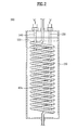
- FIG. 2 is a schematic view illustrating a water heating apparatus according to an embodiment of the present invention.
- a refrigerator having a water heating apparatus includes a body 1 defining an outer shell, a door 2 formed in the front of the body 1, a water supply tube 10 installed in the body 1 so as to be connected with an external water pipe (not shown), a hot water supply tube 40 branched from the water supply tube 10 and having a heat exchanger at a predetermined portion, a cold water supply tube 50 branched from the water supply tube 10.
- a filter 20 for filtering the water fed from an exterior and removing foreign material from the water is installed on the water supply tube 10.
- Three-way valve 30 for controlling the water flow direction is installed on a branch portion of the water supply tube 10, which is branched from the water supply tube 10 to the hot water supply tube 40 and the cold water supply tube 50.
- a hot water supply unit 60 for supplying hot water depending on operation of a hot water supply control lever 65 is installed at an end of the hot water supply tube 40.
- a cold water supply unit 70 for supplying hot water depending on operation of a cold water supply control lever 75 is installed at an end of the cold water supply tube 50.
- a water heating apparatus 100 is arranged on the hot water supply tube 40.
- the hot water heating apparatus 100 includes a heat exchanger 40a provided with a wire wound on a portion of the hot water supply tube 40 to maximize heat transfer area, a case 110 installed to surround a heat exchanger 40a of the hot water supply tube, a heat storage liquid material 120 received in the case 110, and a heater 130 installed in the case 110, for heating the heat storage liquid material 120.
- a temperature sensor 140 for sensing temperature of the heat storage liquid material 120 is installed in the case 110.
- a microcomputer (not shown) for turning the heater 130 on/off depending on the temperature sensed by the temperature sensor 140 is installed in the refrigerator body 1 to control the temperature of the heat storage liquid material 120 more easily.
- the wound wire of the heat exchanger 40a has a spiral shape and the turns of the wire are spaced apart from each other.
- the heat storage liquid material 120 is of material having a high specific heat such as water or paraffin.
- the case 110 is illustrated and described to have a hollow cylindrical shape in this specification but is not limited only to the shape.
- the size and shape of the case 110 depend on the space structure of the refrigerator body 1, the longitudinal length of the heat exchanger 40a and the winding shape of the wound wire.
- an inner surface of the case 110 is coated with ceramic to prevent corrosion and improve heat resistant property and an outer surface of the case 110 is covered with adiabatic material such as glass fiber or synthetic resin to prevent heat from emitting to exterior.
- adiabatic material such as glass fiber or synthetic resin to prevent heat from emitting to exterior.
- the hot water supply tube 40 is preferably of a copper tube or a stainless tube to prevent corrosion and enhance heat conductivity from the heater 130.
- the heater 130 is installed in the case 110, particularly, in a space formed in the heat exchanger 40a in a longitudinal direction. More preferably, the heater 130 is a seizing heater.
- drinking water is fed from an external water supply pipe to the water supply tube 10, filtered through the filter 20 to get rid of foreign material, and fed to the hot water supply tube 40 through the three-way valve 30.
- Microcomputer controls the heater 130 to heat the heat storage liquid material 120, and the heated heat storage liquid material 120 heats the heat exchanger 40a.
- the temperature sensor 140 senses the temperature of the heat storage liquid material 120 continuously. At this time, the microcomputer compares actual temperature and set temperature of the heat storage liquid material 120.
- the microcomputer turns the heater 130 off. If the actual temperature of the heat storage liquid material 120 is lower than the set temperature, the microcomputer turns the heater 130 on. The microcomputer repeats the above-mentioned process to maintain the temperature of the hot water stored in the heat exchanger 40a to be constant.
- the hot water stored in the heat exchanger 40a is fed to the user through the hot water supply unit 60 without a delay.
- the drinking water additionally fed to the hot water supply tube 40 by an amount of hot water fed to the user through the hot water supply tube 40 is rapidly heated while passing through the heat exchanger 40a so that the user can get the desirable amount of the hot water.
- the heat exchanger 40a whose heat transfer area is maximized is formed on the hot water supply unit 40 so that the water passing through the heat exchanger 40a is rapidly heated owing to heat exchange with the heat storage liquid material 120 and fed to the user.
- the heater 130 is turned on/off with a predetermined interval without installing the temperature sensor 140 to generate hot water and supply it to the user.
- hot water can be fed to the user by repeating steps of turning the heater 130 on for a predetermined time to heat the heat exchanger 40a through the heat storage liquid material 120 and generate hot water and then turning the heater 130 off for a predetermined time.
- the on/off time of the heater 130 can be adjusted to efficiently generate hot water and supply it to the user.
- drinking water is fed even to the cold water supply tube 50 and is cooled while passing through the cold water supply tube 50 branched to an evaporator (not shown). So, the cooled water is received in the cold water supply tube 50.
- the cold water received in the cold supply tube 50 is rapidly fed to the user through the cold supply unit 70.
- the additional water fed to the cold supply tube 50 as much as the amount of the fed water is cooled while passing the cold water supply tube 50 branched to an evaporator. So, the user can take the cold water as he or she wants.
- the fed water is rapidly heated using the water heating apparatus including the heat exchanger having the maximized heat transfer area with the heater on the hot water supply tube so that the user can take the hot water as he or she wants.
- hot water is generated by the heat exchanger that has the maximized heat transfer area with the heater, hot water can be fed without installing any additional auxiliary heat source.
Landscapes
- Engineering & Computer Science (AREA)
- Chemical & Material Sciences (AREA)
- Combustion & Propulsion (AREA)
- Physics & Mathematics (AREA)
- Mechanical Engineering (AREA)
- Thermal Sciences (AREA)
- General Engineering & Computer Science (AREA)
- Heat-Pump Type And Storage Water Heaters (AREA)
- Heat-Exchange Devices With Radiators And Conduit Assemblies (AREA)
Applications Claiming Priority (3)
| Application Number | Priority Date | Filing Date | Title |
|---|---|---|---|
| KR2003021949 | 2003-04-08 | ||
| KR10-2003-0021949A KR100519358B1 (ko) | 2003-04-08 | 2003-04-08 | 온수 공급을 위한 순간 가열 장치 및 이를 구비한 냉장고 |
| EP03013413A EP1471315A3 (de) | 2003-04-08 | 2003-06-20 | Heisswassergerät und Kühlschrank mit einem solchen Gerät |
Related Parent Applications (1)
| Application Number | Title | Priority Date | Filing Date |
|---|---|---|---|
| EP03013413A Division EP1471315A3 (de) | 2003-04-08 | 2003-06-20 | Heisswassergerät und Kühlschrank mit einem solchen Gerät |
Publications (2)
| Publication Number | Publication Date |
|---|---|
| EP1522807A2 true EP1522807A2 (de) | 2005-04-13 |
| EP1522807A3 EP1522807A3 (de) | 2005-04-27 |
Family
ID=32960241
Family Applications (2)
| Application Number | Title | Priority Date | Filing Date |
|---|---|---|---|
| EP04029780A Withdrawn EP1522807A3 (de) | 2003-04-08 | 2003-06-20 | Heisswassergerät und Kühlschrank mit einem solchen Gerät |
| EP03013413A Withdrawn EP1471315A3 (de) | 2003-04-08 | 2003-06-20 | Heisswassergerät und Kühlschrank mit einem solchen Gerät |
Family Applications After (1)
| Application Number | Title | Priority Date | Filing Date |
|---|---|---|---|
| EP03013413A Withdrawn EP1471315A3 (de) | 2003-04-08 | 2003-06-20 | Heisswassergerät und Kühlschrank mit einem solchen Gerät |
Country Status (5)
| Country | Link |
|---|---|
| US (1) | US7130533B2 (de) |
| EP (2) | EP1522807A3 (de) |
| JP (1) | JP2004309107A (de) |
| KR (1) | KR100519358B1 (de) |
| CN (1) | CN1536305A (de) |
Cited By (1)
| Publication number | Priority date | Publication date | Assignee | Title |
|---|---|---|---|---|
| CN101881547A (zh) * | 2010-06-25 | 2010-11-10 | 郭维存 | 多能箱 |
Families Citing this family (30)
| Publication number | Priority date | Publication date | Assignee | Title |
|---|---|---|---|---|
| KR100614227B1 (ko) * | 2005-01-03 | 2006-08-21 | 엘지전자 주식회사 | 냉장고의 착탈식 온수가열장치 |
| US20070246200A1 (en) * | 2006-04-25 | 2007-10-25 | Yen Sun Technology Corp. | Heat-exchange module for liquid |
| US8695371B2 (en) * | 2006-12-22 | 2014-04-15 | Whirlpool Corporation | Refrigerator dispenser assembly including a water conditioning cartridge |
| JP4787284B2 (ja) * | 2007-03-27 | 2011-10-05 | ダイキン工業株式会社 | ヒートポンプ式給湯装置 |
| CN102116565B (zh) * | 2011-01-21 | 2013-01-09 | 合肥美的荣事达电冰箱有限公司 | 冰箱的供水装置及具有该供水装置的冰箱 |
| US8651331B2 (en) | 2011-10-31 | 2014-02-18 | General Electric Company | Refrigeration appliance with chilled water dispenser |
| US8651330B2 (en) | 2011-10-31 | 2014-02-18 | General Electric Company | Refrigeration appliance with hot water dispenser |
| US9528749B2 (en) | 2011-11-02 | 2016-12-27 | Lg Electronics Inc. | Refrigerator |
| KR101861831B1 (ko) | 2011-11-02 | 2018-05-29 | 엘지전자 주식회사 | 진공 공간부를 구비하는 냉장고 |
| KR101832763B1 (ko) | 2011-11-02 | 2018-02-28 | 엘지전자 주식회사 | 진공 공간부를 구비하는 냉장고 |
| KR101861832B1 (ko) | 2011-11-04 | 2018-05-29 | 엘지전자 주식회사 | 진공 공간부를 구비하는 냉장고 |
| CN102374742A (zh) * | 2011-12-06 | 2012-03-14 | 合肥美的荣事达电冰箱有限公司 | 一种具有饮水机的冰箱 |
| US20130209078A1 (en) * | 2012-02-14 | 2013-08-15 | Imi Cornelius Inc | Hot beverage dispensing system |
| ITVI20120234A1 (it) * | 2012-09-24 | 2014-03-25 | Ht S P A | Procedimento per la realizzazione di elementi riscaldanti che impiegano resistori elettrici |
| US9320993B2 (en) | 2012-11-12 | 2016-04-26 | Whirlpool Corporation | Filter housing for small media |
| US9327216B2 (en) | 2012-11-12 | 2016-05-03 | Whirlpool Corporation | Customizable multi-stage water treatment system |
| US9889478B2 (en) | 2012-11-12 | 2018-02-13 | Whirlpool Corporation | Consumable descaling cartridges for a refrigerator appliance |
| US9314716B2 (en) | 2012-11-12 | 2016-04-19 | Whirlpool Corporation | Customizable multi-stage water treatment assembly |
| US20140169774A1 (en) * | 2012-12-18 | 2014-06-19 | General Electric Company | Water heating assembly for a refrigerator appliance |
| JP2014173822A (ja) * | 2013-03-13 | 2014-09-22 | Hitachi Appliances Inc | 電気温水器 |
| US8967432B2 (en) | 2013-03-15 | 2015-03-03 | Electrolux Home Products, Inc. | Refrigerator appliance with hot water dispenser |
| US9139415B2 (en) | 2013-03-15 | 2015-09-22 | Electrolux Home Products, Inc. | Refrigerator appliance with hot water dispenser |
| US20150083384A1 (en) * | 2013-09-26 | 2015-03-26 | General Electric Company | Appliance with timed preheating for dispensed fluids |
| US9352950B2 (en) * | 2013-11-26 | 2016-05-31 | General Electric Company | Refrigerator appliance and method for use with single serve dispenser |
| KR102207295B1 (ko) * | 2014-02-12 | 2021-01-26 | 엘지전자 주식회사 | 냉장고, 냉장고의 온수공급시스템, 및 냉장고의 온수공급방법 |
| DE202014103193U1 (de) * | 2014-07-11 | 2015-07-15 | Better Place GmbH | Zirkulationsleitung für Kaltwasser |
| CN108599137B (zh) * | 2017-12-28 | 2020-03-31 | 东南大学 | 考虑区域热网暂态传热特性的多能流系统优化运行方法 |
| CN110513864B (zh) * | 2019-09-06 | 2021-12-28 | 芜湖美的厨卫电器制造有限公司 | 加热器和制热设备 |
| US20230250964A1 (en) * | 2022-02-08 | 2023-08-10 | Sabrina L. Harmon | Multi-functional stove |
| KR102934660B1 (ko) * | 2025-08-28 | 2026-03-04 | 김은주 | 에너지 절감형 고열 응축 발열 보일러 |
Family Cites Families (23)
| Publication number | Priority date | Publication date | Assignee | Title |
|---|---|---|---|---|
| US1595819A (en) * | 1925-06-18 | 1926-08-10 | Ludwig L Bluemlein | Water heater |
| FR794940A (fr) * | 1935-06-06 | 1936-02-28 | Chauffe-eau courante électrique | |
| DE1126898B (de) * | 1958-09-26 | 1962-04-05 | Willi Brandl | Erhitzer fuer Fluessigkeiten, insbesondere OEle |
| GB1574406A (en) * | 1976-03-12 | 1980-09-03 | Secr Defence | Heat storage for a diver |
| GB2035764A (en) * | 1978-11-22 | 1980-06-18 | Mars Ltd | Electric water heater |
| JPS57136081A (en) | 1981-02-18 | 1982-08-21 | Hitachi Ltd | Refrigerator with hot water feeder |
| JPS58173387A (ja) * | 1982-03-31 | 1983-10-12 | Takashi Miyagawa | 熱交換器 |
| US4602145A (en) * | 1984-07-23 | 1986-07-22 | Bloomfield Industries, Inc. | Tap-off hot water system for electric beverage making device |
| JPS61252467A (ja) | 1985-05-02 | 1986-11-10 | ホシザキ電機株式会社 | 給湯機付冷却装置 |
| DE3680161D1 (de) * | 1985-07-22 | 1991-08-14 | Matsushita Electric Industrial Co Ltd | Elektrischer durchlauferhitzer. |
| FR2588360B1 (fr) * | 1985-10-04 | 1989-03-24 | Bidaux Alain | Prechauffeur a bain-marie multicombustible |
| DE4201944C2 (de) * | 1991-01-24 | 2003-04-24 | Asahi Glass Co Ltd | Flüssigkeitsheizeinrichtung |
| US5590240A (en) | 1995-05-30 | 1996-12-31 | Process Technology Inc | Ultra pure water heater with coaxial helical flow paths |
| JPH094958A (ja) | 1995-06-22 | 1997-01-10 | Toshiba Corp | 冷温水機 |
| JPH09243173A (ja) | 1996-03-06 | 1997-09-16 | Nippon Itomitsuku:Kk | 飲料用熱湯・冷水器 |
| US5715569A (en) * | 1996-09-18 | 1998-02-10 | Dickey; Roy E. | Vacuum cleaner accessory for water heaters |
| KR100199980B1 (ko) | 1997-05-17 | 1999-06-15 | 윤종용 | 냉장고용 워터디스펜서 |
| KR100246399B1 (ko) * | 1997-09-23 | 2000-04-01 | 구자홍 | 냉장고용 디스펜서어셈블리 및 그 제어방법 |
| JP2000304432A (ja) | 1999-04-23 | 2000-11-02 | Lg Electronics Inc | 温水器付き冷蔵庫 |
| US6173118B1 (en) * | 1999-06-15 | 2001-01-09 | Howard Harris Building Inc. | Sensor block and automatic fill valve for water with immersed copper fluid coil |
| KR20010008272A (ko) * | 2000-11-20 | 2001-02-05 | 구현석 | 냉장고의 냉온수장치 결합구조 |
| US6577817B2 (en) * | 2001-07-03 | 2003-06-10 | Howard Harris Builder | Water heater |
| KR100487768B1 (ko) * | 2003-03-03 | 2005-05-06 | 엘지전자 주식회사 | 온수디스펜서를 구비한 냉장고 |
-
2003
- 2003-04-08 KR KR10-2003-0021949A patent/KR100519358B1/ko not_active Expired - Fee Related
- 2003-06-20 US US10/465,617 patent/US7130533B2/en not_active Expired - Lifetime
- 2003-06-20 EP EP04029780A patent/EP1522807A3/de not_active Withdrawn
- 2003-06-20 EP EP03013413A patent/EP1471315A3/de not_active Withdrawn
- 2003-06-27 CN CNA031484387A patent/CN1536305A/zh active Pending
- 2003-08-13 JP JP2003207443A patent/JP2004309107A/ja active Pending
Cited By (1)
| Publication number | Priority date | Publication date | Assignee | Title |
|---|---|---|---|---|
| CN101881547A (zh) * | 2010-06-25 | 2010-11-10 | 郭维存 | 多能箱 |
Also Published As
| Publication number | Publication date |
|---|---|
| EP1522807A3 (de) | 2005-04-27 |
| EP1471315A3 (de) | 2005-03-23 |
| KR20040087520A (ko) | 2004-10-14 |
| EP1471315A2 (de) | 2004-10-27 |
| US20040202457A1 (en) | 2004-10-14 |
| KR100519358B1 (ko) | 2005-10-07 |
| US7130533B2 (en) | 2006-10-31 |
| JP2004309107A (ja) | 2004-11-04 |
| CN1536305A (zh) | 2004-10-13 |
Similar Documents
| Publication | Publication Date | Title |
|---|---|---|
| US7130533B2 (en) | Water heating apparatus and refrigerator having the same | |
| US5233970A (en) | Semi-instantaneous water heater with helical heat exchanger | |
| CA2248865A1 (en) | Continuously cleaned pressureless water heater with immersed copper fluid coil | |
| US20120051724A1 (en) | instantaneous water heating unit for insertion into a hot water storage tank | |
| EP3172497B1 (de) | Chauffe-eau et application | |
| US7832466B2 (en) | Water supply system | |
| US20150345827A1 (en) | Hot water tank attached to boiler | |
| US20040149742A1 (en) | System to heat liquids | |
| US20080053383A1 (en) | Flash steam generator | |
| EP0059692A3 (de) | Kombinierte Kühl- und Wasserheizungsanlage | |
| KR100626457B1 (ko) | 순간 가열 장치 및 냉장고 | |
| CN206656495U (zh) | 水箱组件和具有其的热泵热水机组 | |
| KR200379106Y1 (ko) | 폐열회수장치 | |
| CN101065620B (zh) | 热水器以及操作该热水器的方法 | |
| CN209960762U (zh) | 一种电热水器 | |
| GB2097908A (en) | Heating water in a domestic water circuit | |
| CN1322283C (zh) | 电热水器的加热装置及加热方法 | |
| CN222675963U (zh) | 一种节能电热水瓶 | |
| KR100539563B1 (ko) | 냉장고용 온수공급장치 | |
| JPH04106370A (ja) | 給湯装置 | |
| CN209877366U (zh) | 热泵热水器 | |
| GB2088030A (en) | Hot water cylinder | |
| KR200286553Y1 (ko) | 보일러 폐열 저장식 절수장치 | |
| KR200194949Y1 (ko) | 주름(凹,凸)성형 관 히트파이프,열 교환기 | |
| KR101377587B1 (ko) | 음용수 순간 가열 장치 |
Legal Events
| Date | Code | Title | Description |
|---|---|---|---|
| PUAI | Public reference made under article 153(3) epc to a published international application that has entered the european phase |
Free format text: ORIGINAL CODE: 0009012 |
|
| PUAL | Search report despatched |
Free format text: ORIGINAL CODE: 0009013 |
|
| AC | Divisional application: reference to earlier application |
Ref document number: 1471315 Country of ref document: EP Kind code of ref document: P |
|
| AK | Designated contracting states |
Kind code of ref document: A2 Designated state(s): AT BE BG CH CY CZ DE DK EE ES FI FR GB GR HU IE IT LI LU MC NL PT RO SE SI SK TR |
|
| AX | Request for extension of the european patent |
Extension state: AL LT LV MK |
|
| AK | Designated contracting states |
Kind code of ref document: A3 Designated state(s): AT BE BG CH CY CZ DE DK EE ES FI FR GB GR HU IE IT LI LU MC NL PT RO SE SI SK TR |
|
| AX | Request for extension of the european patent |
Extension state: AL LT LV MK |
|
| RIN1 | Information on inventor provided before grant (corrected) |
Inventor name: KIM, SHIN III Inventor name: LEE, MYUNG RYUL Inventor name: KIM, SEONG JAE |
|
| 17P | Request for examination filed |
Effective date: 20050908 |
|
| AKX | Designation fees paid |
Designated state(s): DE FR GB IT |
|
| 17Q | First examination report despatched |
Effective date: 20070522 |
|
| STAA | Information on the status of an ep patent application or granted ep patent |
Free format text: STATUS: THE APPLICATION IS DEEMED TO BE WITHDRAWN |
|
| 18D | Application deemed to be withdrawn |
Effective date: 20071002 |