EP1522765A2 - Tensioner lever - Google Patents
Tensioner lever Download PDFInfo
- Publication number
- EP1522765A2 EP1522765A2 EP04022016A EP04022016A EP1522765A2 EP 1522765 A2 EP1522765 A2 EP 1522765A2 EP 04022016 A EP04022016 A EP 04022016A EP 04022016 A EP04022016 A EP 04022016A EP 1522765 A2 EP1522765 A2 EP 1522765A2
- Authority
- EP
- European Patent Office
- Prior art keywords
- region
- guide region
- tensioner lever
- lever
- tensioner
- Prior art date
- Legal status (The legal status is an assumption and is not a legal conclusion. Google has not performed a legal analysis and makes no representation as to the accuracy of the status listed.)
- Withdrawn
Links
Images


Classifications
-
- F—MECHANICAL ENGINEERING; LIGHTING; HEATING; WEAPONS; BLASTING
- F16—ENGINEERING ELEMENTS AND UNITS; GENERAL MEASURES FOR PRODUCING AND MAINTAINING EFFECTIVE FUNCTIONING OF MACHINES OR INSTALLATIONS; THERMAL INSULATION IN GENERAL
- F16H—GEARING
- F16H7/00—Gearings for conveying rotary motion by endless flexible members
- F16H7/08—Means for varying tension of belts, ropes or chains
-
- F—MECHANICAL ENGINEERING; LIGHTING; HEATING; WEAPONS; BLASTING
- F16—ENGINEERING ELEMENTS AND UNITS; GENERAL MEASURES FOR PRODUCING AND MAINTAINING EFFECTIVE FUNCTIONING OF MACHINES OR INSTALLATIONS; THERMAL INSULATION IN GENERAL
- F16H—GEARING
- F16H7/00—Gearings for conveying rotary motion by endless flexible members
- F16H7/08—Means for varying tension of belts, ropes or chains
- F16H2007/0863—Finally actuated members, e.g. constructional details thereof
- F16H2007/0872—Sliding members
Definitions
- This invention relates to a tensioner lever of the type used in the timing transmission of an automobile engine, or in a similar machine where power is transmitted by an endless, flexible, transmission medium, such as a roller chain or a silent chain, from a driving sprocket to one or more driven sprockets.
- an endless, flexible, transmission medium such as a roller chain or a silent chain
- the purpose of the tensioner lever is to preventing transmission failure due to excessive tension or excessive looseness of the transmission chain.
- the lever comprises an arm, pivotable about a pivot axis adjacent one end of the lever, and a shoe extending lengthwise along the arm, from one end of the arm to the other
- the curvature of the chain-engaging surface of the shoe is uniform. That is, it has a constant radius of curvature.
- the shoe of a conventional tensioner lever since the shoe of a conventional tensioner lever has a long abutment region, the distance between the shafts of the driving sprocket and the driven sprocket is necessarily long.
- the length of the tensioner lever therefore, requires the engine to be large for a given engine output.
- the lengths of the spans of chain between the sprockets also results in excessive noise due to vibration of the chain.
- Object of this invention is to provide an improved tensioner level.
- the power transmission in accordance with the invention comprises an endless, flexible transmission medium, engaged with a driving sprocket and a driven sprocket, and a tensioner lever for applying a tensioning force to the slack side of the transmission medium returning from the driving sprocket to a driven sprocket.
- the tensioner lever has an arc-shaped shoe surface, which abuts the slack side of the transmission medium in sliding contact therewith.
- the tensioner lever is pivoted for rotation toward and away from the slack side of the transmission medium, about a pivot axis adjacent the driving sprocket and extending toward the driven sprocket.
- the lever has a first end adjacent the pivot axis and a tip remote from the pivot axis.
- the arc-shaped shoe surface comprises a curved guide region extending from a location adjacent the first end of the lever, for guiding and controlling a portion of the slack side of the transmission medium moving from the location adjacent the first end of the shoe surface toward the driven sprocket, and a curved pressing region, continuous with the curved guide region, and extending toward the tip, for taking up slack in a portion of the slack side of the transmission medium moving from the guide region toward the driven sprocket.
- the radius of curvature of the curved guide region is greater than the radius of curvature of the curved pressing region.
- the transmission medium which approaches the pivot end of the lever, is sufficiently guided and controlled on the curved guide region of the lever, and it is not necessary to depend on the portion of the lever near its tip for guiding and controlling the approaching portion of the transmission medium.
- the tensioner lever according to the invention can be freely designed to adapt to changes in sliding resistance, in tension, and in the line of travel, which are apt to occur in the transmission medium.
- greater freedom in the design of layout of a transmission device can be realized.
- the length of the guide region can be shortened, whereby the transmission device can be made more compact as compared with a transmission device utilizing a conventional tensioner in which the arc-shaped shoe surface has a constant curvature.
- the tensioner lever in accordance with the invention maintains the required tension in an endless, flexible transmission medium which travels around a driving sprocket and one or more driven sprockets,
- the lever is pivoted on an axis adjacent the end approached by the transmission medium as it travels away from the driving sprocket.
- an arc-shaped shoe surface is in sliding contact with the endless, flexible, transmission medium.
- the curved shoe surface comprises two regions.
- the first region is a curved guide surface region, which guides and controls the approaching transmission medium.
- the second region is a curved pressing surface region, continuous with the guide surface region, for absorbing slack in the portion of the transmission medium between the tip of the lever and the driven sprocket.
- the structure of the tensioner lever can take any of a broad variety of forms.
- the lever can comprise a synthetic resin shoe on which the transmission chain slides, and a cast aluminum base, which maintains the form of the synthetic shoe member.
- the shoe and base are integrally locked by hooks protruding from both sides of the shoe.
- a metal reinforcing plate fits into a longitudinal slot provided in a synthetic resin guide body on which the transmission chain slides.
- a “sandwich-molded" lever a core of a slide rail, and a core of rail support, are integrated by a skin layer formed by a sandwich molding process.
- any of a variety of endless, flexible, transmission media may be used with the tensioner lever of the invention.
- a transmission chain such as a roller chain, a silent chain or the like may be used, and, alternatively, a transmission belt such as a toothed belt or the like may also be used.
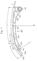
- the tensioner lever 100 in accordance with the invention is pivoted on a shaft 120, which can protrude from an engine block (not shown).
- the tensioner lever 100 can be of the hook-locking type, in which a synthetic resin shoe 100a, on which a transmission chain C slides, and a die-cast aluminum base 100b, for holding the shoe 100a, are integrally locked to each other by hooks 100c protruding from both sides of the shoe 100a.
- An arc-shaped shoe surface 110 which is in sliding contact with the transmission chain C, comprises a curved guide region 111, which guides and controls the part of the transmission chain C approaching the pivoted end of the lever, and a curved pressing region 112, which is continuous with the guide region 111, and absorbs slack in the part of the transmission chain C moving away from the tip the tensioner lever 100.
- the convex, curved, shoe surface 110 faces the transmission chain C, and a pad 130 on the opposite side of the tensioner lever 100 is engaged by a plunger (not shown), which protrudes from a tensioner, The plunger, in cooperation with the tensioner lever 100, imparts the required tension to the transmission chain C, which travels between a driving sprocket and a driven sprocket in an automobile engine (not shown in FIG. 1).
- the arc-shaped shoe surface 110 comprises a guide region 111 and a pressing region 112
- an extremely short, curved, introduction region may be provided ahead of, and continuous with, the guide region 111, for introducing the transmission chain C smoothly to the guide region 111 as it approaches the end of the tensioner lever 100 adjacent the pivot shaft 120.
- the radius of curvature R of the guide region 111 is larger than the radius of curvature r of the pressing region 112. Consequently the arc-shaped shoe surface 110 is bent further than the shoe surface of a conventional tensioner in which the shoe surface has a constant curvature.
- the length L of the guide region 111, and the length 1 the pressing region 112 are related by a ratio of approximately 3 : 1.
- the part of the transmission chain C approaching the end of the tensioner lever 100 near the pivot shaft 120 is guided and controlled along a gentle traveling line.
- the radius of curvature R of the guide region 111 is 300 mm or more because of a space factor such as the distance between the crankshaft and a camshaft in an engine
- the length 1 of the pressing region 112 is desirably at least one-fourth the length L of the guide region 111.
- the radius of curvature R of the guide region 111 is 300 mm or less
- the length 1 of the pressing region 112 is desirably at least one-third the length L of the guide region 111.
- the border at which the guide region 111 and the pressing region 112 meet is continuous and has a gentle slope, so that significant wear, which would otherwise be generated as the transmission chain C slides on the shoe surface 110, can be avoided.
- the shoe surface 110 comprises a guide region 111 extending toward the tip of the tensioner lever 100 from the end of the tensioner lever 100 adjacent the pivot shaft 120, and a pressing curve region 112 extending from the guide region 111 toward the tip of the tensioner lever 100, the transmission chain C, approaching the end of the tensioner lever 100 adjacent the pivot shaft 120, is guided and controlled by the guide region 111.
- driving sprocket S1 which is on a crankshaft, rotates as shown by an arrow, and meshes with chain C, which delivers rotational power to camshaft sprockets S2, the direction of rotation of which is also indicated by arrows.
- the operating conditions of the tensioner lever 100 in FIG. 1 are shown schematically for easy comprehension.
- the lever structure is the same as in FIG. 1.
- the tensioner lever 100 of the invention can be shorter than the conventional tensioner lever 500, which has a simple, arc-shaped shoe surface, but can still perform satisfactorily.
- the tensioner lever 100 in accordance with the invention provides the transmission designer with greater freedom to design a transmission that adapts to different sliding resistances, changes in tension, and changes in the chain traveling line, which are apt to occur over time in the operation of the transmission chain C.
- the invention provides greater flexibility in automobile engine design.
- the length of the guide region 111 is shortened by the fact that the curvature r of the pressing region 112 is smaller than the curvature R of the guide region 111.
- the overall length of the tensioner lever 100 can be made shorter as compared with the conventional tensioner lever 500 in which the shoe surface has a constant curvature. Accordingly, the invention can contribute to significant improvement in the compactness of an automobile engine.
Landscapes
- Engineering & Computer Science (AREA)
- General Engineering & Computer Science (AREA)
- Mechanical Engineering (AREA)
- Devices For Conveying Motion By Means Of Endless Flexible Members (AREA)
Abstract
Description
- FIG. 1
- is a schematic side elevational view of a tensioner lever in accordance with the invention,
- FIG. 2
- is a two-part schematic view of a timing transmission, showing the path of travel of the timing chain and comparing the length of a conventional tensioner lever to the length of a tensioner lever in accordance with the invention,
- FIG. 3
- is a two-part schematic view, similar to FIG. 2, comparing a conventional transmission and a smaller transmission in which a the tensioner lever in accordance with the invention is used, and
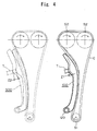
- FIG. 4
- is a two-part schematic view of a conventional timing transmission and a timing transmission in accordance with the invention, showing differences between the tensioner plunger strokes.
- 100, 500
- tensioner lever
- 100a
- shoe
- 100b
- base
- 100c
- hook
- 110
- shoe surface
- 111
- guide region
- 112
- pressing region
- 120
- shaft
- 130
- pad
- C
- transmission chain
- L
- length of the
guide region 111 - I
- length the
pressing region 112 - R
- radius of curvature of the
guide region 111 - r
- radius of curvature of the
pressing region 112 - S1
- driving sprocket
- S2
- camshaft sprocket, driven sprocket
- T
- tensioner
- Y
- distance
- Z1,
- Z2 plunger stroke
Claims (5)
- Power transmission comprising an endless, flexible transmission medium (C) engaged with a driving sprocket (S1) and a driven sprocket (S2), and a tensioner lever (100) for applying a tensioning force to the slack side of the transmission medium (C) returning from the driving sprocket (S1) to a driven sprocket (S2), the tensioner lever (100) having an arc-shaped shoe surface (110), which abuts the slack side of the transmission medium (C) in sliding contact therewith, the tensioner lever (100) being pivoted for rotation toward and away from the slack side about a pivot axis adjacent the driving sprocket (S1) and extending toward the driven sprocket (S2), the tensioner lever (100) having a first end adjacent the pivot axis and having a tip remote from the pivot axis, the arc-shaped shoe surface (110) comprising a curved guide region (111) extending from a location adjacent the first end, for guiding and controlling a portion of the slack side of the transmission medium (C) moving from the location adjacent the first end of the shoe surface (110) toward the driven sprocket (S2), and a curved pressing region (112), continuous with the curved guide region (111) and extending toward the tip, for taking up slack in a portion of the slack side of the transmission medium (C) moving from the guide region (111) toward the driven sprocket (S2), in which the radius (R) of curvature of the curved guide region (111) is greater than the radius (r) of curvature of the curved pressing region (112).
- Tensioner lever for applying a tensioning force to the slack side of an endless, flexible, transmission medium (C) returning from a driving sprocket (S1) to a driven sprocket (S2), the tensioner lever (100) having an arc-shaped shoe surface (110), for abutting the slack side in sliding contact therewith, the tensioner lever (100) having a first end and a tip remote from the first end, and being pivotable about a pivot axis adjacent the first end, the arc-shaped shoe surface (110) comprising a curved guide region (111) extending from a location adjacent the first end, for guiding and controlling a portion of the slack side of a transmission medium moving from the location adjacent the first end of the shoe surface (110) toward a driven sprocket (S2), and a curved pressing region (112), continuous with the curved guide region (111) and extending toward the tip, for taking up slack in a portion of the slack side of the transmission medium (C) moving from the guide region (111) toward the driven sprocket (S2), in which the radius (R) of curvature of the curved guide (111) region is greater than the radius (r) of curvature of the curved pressing region (112).
- Tensioner according to claim 2, characterized in that a length (L) of the guide region (111), and a length (1) the pressing region (112), are related by a ratio of approximately 3 : 1 to 4 : 1.
- Tensioner according to claim 3, characterized in that in a case where the radius (R) of curvature of the guide region (111) is 300 mm or more the length (L) of the guide region (111), and the length (1) is at least one-fourth the length (L) of the guide region (111).
- Tensioner according to claim 3, characterized in that in a case where the radius (R) of curvature of the guide region (111) is 300 mm or less the length (L) of the guide region (111), and the length (1) is at least one-third the length (L) of the guide region (111).
Applications Claiming Priority (2)
| Application Number | Priority Date | Filing Date | Title |
|---|---|---|---|
| JP2003352105A JP2005114126A (en) | 2003-10-10 | 2003-10-10 | Tensioner lever |
| JP2003352105 | 2003-10-10 |
Publications (2)
| Publication Number | Publication Date |
|---|---|
| EP1522765A2 true EP1522765A2 (en) | 2005-04-13 |
| EP1522765A3 EP1522765A3 (en) | 2009-06-17 |
Family
ID=34309286
Family Applications (1)
| Application Number | Title | Priority Date | Filing Date |
|---|---|---|---|
| EP04022016A Withdrawn EP1522765A3 (en) | 2003-10-10 | 2004-09-16 | Tensioner lever |
Country Status (4)
| Country | Link |
|---|---|
| US (1) | US20050079938A1 (en) |
| EP (1) | EP1522765A3 (en) |
| JP (1) | JP2005114126A (en) |
| CN (1) | CN1605770A (en) |
Families Citing this family (12)
| Publication number | Priority date | Publication date | Assignee | Title |
|---|---|---|---|---|
| JP4060320B2 (en) * | 2005-03-07 | 2008-03-12 | 株式会社椿本チエイン | Movable guide for transmission |
| DE602007008151D1 (en) * | 2007-03-27 | 2010-09-09 | Dayco Europe Srl | DRIVE FOR A COMBUSTION ENGINE WITH AN OIL-BASED TIMING BELT AND A SPANISH SHOE |
| JP4386378B2 (en) * | 2007-07-31 | 2009-12-16 | 株式会社椿本チエイン | Tensioner lever |
| JP5634356B2 (en) | 2011-08-31 | 2014-12-03 | 株式会社椿本チエイン | Guide for transmission |
| JP5631825B2 (en) | 2011-09-07 | 2014-11-26 | 株式会社椿本チエイン | Guide for transmission |
| JP2013083292A (en) | 2011-10-07 | 2013-05-09 | Tsubakimoto Chain Co | Transmission guide |
| JP5513576B2 (en) * | 2012-09-26 | 2014-06-04 | 富士重工業株式会社 | Chain tensioner lever |
| DE102013224126A1 (en) * | 2013-11-26 | 2015-05-28 | Schaeffler Technologies AG & Co. KG | Clamping rail for a traction mechanism drive of an internal combustion engine |
| CN106051077A (en) * | 2016-07-29 | 2016-10-26 | 辽宁正时动力传动科技有限公司 | V-shaped gasoline engine timing tooth chain transmission system |
| RU209304U1 (en) * | 2021-09-16 | 2022-03-15 | Вячеслав Евгеньевич Быков | Shoe of the tensioner of the drive element of the chain of the gas distribution mechanism of the internal combustion engine |
| RU208097U1 (en) * | 2021-09-16 | 2021-12-02 | Вячеслав Евгеньевич Быков | Timing chain tensioner shoe for internal combustion engine timing chain |
| CN113695200B (en) * | 2021-10-12 | 2022-09-23 | 郑州中远防务材料有限公司 | Transmission device for splicing unidirectional cloth on strips |
Family Cites Families (8)
| Publication number | Priority date | Publication date | Assignee | Title |
|---|---|---|---|---|
| US4826468A (en) * | 1987-11-18 | 1989-05-02 | Klifa Fahrzeugteile Gmbh & Co. | Chain tensioner |
| JPH089476Y2 (en) * | 1991-11-07 | 1996-03-21 | 株式会社椿本チエイン | Integrated structure of chain guide arm and shoe |
| JP3448122B2 (en) * | 1995-01-20 | 2003-09-16 | 株式会社椿本チエイン | Tensioner lever |
| JP3385961B2 (en) * | 1998-03-23 | 2003-03-10 | トヨタ自動車株式会社 | Chain transmission |
| JP3253951B1 (en) * | 2000-12-15 | 2002-02-04 | 株式会社椿本チエイン | Plastic movable guide for transmission |
| JP3384560B2 (en) * | 2001-03-13 | 2003-03-10 | 株式会社椿本チエイン | Movable guide for transmission |
| JP3336336B1 (en) * | 2001-08-22 | 2002-10-21 | 株式会社椿本チエイン | Tensioner lever for transmission |
| JP3516940B2 (en) * | 2001-10-23 | 2004-04-05 | 株式会社椿本チエイン | Plastic movable guide for transmission |
-
2003
- 2003-10-10 JP JP2003352105A patent/JP2005114126A/en active Pending
-
2004
- 2004-08-24 US US10/926,239 patent/US20050079938A1/en not_active Abandoned
- 2004-09-16 EP EP04022016A patent/EP1522765A3/en not_active Withdrawn
- 2004-09-30 CN CN200410085581.XA patent/CN1605770A/en active Pending
Also Published As
| Publication number | Publication date |
|---|---|
| EP1522765A3 (en) | 2009-06-17 |
| US20050079938A1 (en) | 2005-04-14 |
| CN1605770A (en) | 2005-04-13 |
| JP2005114126A (en) | 2005-04-28 |
Similar Documents
| Publication | Publication Date | Title |
|---|---|---|
| US20050079938A1 (en) | Tensioner lever | |
| US7951029B2 (en) | Guide for transmission device | |
| KR101411147B1 (en) | Chain | |
| US5184983A (en) | Floating preventive structure for shoe of tensioner lever | |
| US7686718B2 (en) | Timing chain drive system | |
| US7815533B2 (en) | Camshaft drive system for internal combustion engine | |
| EP2140170B1 (en) | Drive for an internal combustion engine comprising an oil wet toothed belt and a tensioning shoe | |
| RU2003112673A (en) | DOUBLE LINEAR STRAPPING DEVICE | |
| CA1288615C (en) | Variable camshaft timing system | |
| JPS61261607A (en) | Valve opening timing control device for internal-combustion engine | |
| JP5127712B2 (en) | Chain guide and tensioner assembly | |
| EP1503109B1 (en) | Lever for a transmission device | |
| JP4065169B2 (en) | Chain tensioner device | |
| JP2000161073A (en) | Chain drive for internal combustion engine | |
| EP1312830B1 (en) | Plastic movable guide for transmission device | |
| US7018312B2 (en) | Chain tensioner | |
| CN105593568B (en) | Drive train including oil-wet toothed belt | |
| US7404777B2 (en) | Power transmission incorporating tensioner lever | |
| US11473652B2 (en) | Chain guide | |
| EP1323949B1 (en) | Hydraulic tensioner with stop mechanism | |
| JP2002098203A (en) | Chain tensioner device | |
| US20260092639A1 (en) | Chain | |
| JPH1068452A (en) | Tensioner of chain | |
| KR20020041095A (en) | Chain guide of engine | |
| CN113330231A (en) | Chain guide and chain transmission device using the same |
Legal Events
| Date | Code | Title | Description |
|---|---|---|---|
| PUAI | Public reference made under article 153(3) epc to a published international application that has entered the european phase |
Free format text: ORIGINAL CODE: 0009012 |
|
| AK | Designated contracting states |
Kind code of ref document: A2 Designated state(s): AT BE BG CH CY CZ DE DK EE ES FI FR GB GR HU IE IT LI LU MC NL PL PT RO SE SI SK TR |
|
| AX | Request for extension of the european patent |
Extension state: AL HR LT LV MK |
|
| PUAL | Search report despatched |
Free format text: ORIGINAL CODE: 0009013 |
|
| AK | Designated contracting states |
Kind code of ref document: A3 Designated state(s): AT BE BG CH CY CZ DE DK EE ES FI FR GB GR HU IE IT LI LU MC NL PL PT RO SE SI SK TR |
|
| AX | Request for extension of the european patent |
Extension state: AL HR LT LV MK |
|
| 17P | Request for examination filed |
Effective date: 20090626 |
|
| AKX | Designation fees paid |
Designated state(s): DE FR GB |
|
| 17Q | First examination report despatched |
Effective date: 20101122 |
|
| STAA | Information on the status of an ep patent application or granted ep patent |
Free format text: STATUS: THE APPLICATION HAS BEEN WITHDRAWN |
|
| 18W | Application withdrawn |
Effective date: 20110209 |