EP1522727A2 - Dosing pump - Google Patents
Dosing pump Download PDFInfo
- Publication number
- EP1522727A2 EP1522727A2 EP04023691A EP04023691A EP1522727A2 EP 1522727 A2 EP1522727 A2 EP 1522727A2 EP 04023691 A EP04023691 A EP 04023691A EP 04023691 A EP04023691 A EP 04023691A EP 1522727 A2 EP1522727 A2 EP 1522727A2
- Authority
- EP
- European Patent Office
- Prior art keywords
- syringes
- dosing pump
- pump according
- base plate
- control device
- Prior art date
- Legal status (The legal status is an assumption and is not a legal conclusion. Google has not performed a legal analysis and makes no representation as to the accuracy of the status listed.)
- Withdrawn
Links
Images



Classifications
-
- F—MECHANICAL ENGINEERING; LIGHTING; HEATING; WEAPONS; BLASTING
- F04—POSITIVE - DISPLACEMENT MACHINES FOR LIQUIDS; PUMPS FOR LIQUIDS OR ELASTIC FLUIDS
- F04B—POSITIVE-DISPLACEMENT MACHINES FOR LIQUIDS; PUMPS
- F04B7/00—Piston machines or pumps characterised by having positively-driven valving
- F04B7/0019—Piston machines or pumps characterised by having positively-driven valving a common distribution member forming a single discharge distributor for a plurality of pumping chambers
- F04B7/0026—Piston machines or pumps characterised by having positively-driven valving a common distribution member forming a single discharge distributor for a plurality of pumping chambers and having an oscillating movement
-
- F—MECHANICAL ENGINEERING; LIGHTING; HEATING; WEAPONS; BLASTING
- F04—POSITIVE - DISPLACEMENT MACHINES FOR LIQUIDS; PUMPS FOR LIQUIDS OR ELASTIC FLUIDS
- F04B—POSITIVE-DISPLACEMENT MACHINES FOR LIQUIDS; PUMPS
- F04B13/00—Pumps specially modified to deliver fixed or variable measured quantities
-
- F—MECHANICAL ENGINEERING; LIGHTING; HEATING; WEAPONS; BLASTING
- F04—POSITIVE - DISPLACEMENT MACHINES FOR LIQUIDS; PUMPS FOR LIQUIDS OR ELASTIC FLUIDS
- F04B—POSITIVE-DISPLACEMENT MACHINES FOR LIQUIDS; PUMPS
- F04B13/00—Pumps specially modified to deliver fixed or variable measured quantities
- F04B13/02—Pumps specially modified to deliver fixed or variable measured quantities of two or more fluids at the same time
Definitions
- the invention relates to a metering pump, in particular for very small quantities.
- the invention provides a dosing pump to be proposed, which has a simple structure has and can be used in conventional syringes as pumping elements.
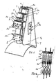
- FIG. 1 shows a front view of the metering pump without the syringes inserted therein, which are shown in FIG. 1a are shown schematically.
- a base plate 1 ( Figures 2 and 3) approximately in the middle of a clamping device 2 fixedly mounted on the front clamping screws 2a for the syringes 3 to be used in the clamping device or their cylinders 3c are provided.
- six clamping screws 2a for six syringes 3 provided.
- six V-shaped grooves 2b are formed, wherein in each case a syringe barrel is inserted into such a V-shaped groove 2b.
- this Grooves 2b opposite is an elongated clamping piece 2c with a corresponding V-shaped Nut arranged, which is in communication with the associated clamping screw 2a and can be moved back and forth by them in the direction of the V-groove 2b to a syringe barrel clamp or release, as shown in FIG. 3.
- Fig. 1a shows schematically that the piston rod 3b in one of the fork-shaped Holder 5b is located.
- Fig. 3 clamping screws are reproduced (Fig. 3), through which a Pusher plate 3a of a piston can be clamped without clearance in the transverse groove 5a.
- a preferably transparent housing part 1b is reproduced, which is the piston slide covers.
- a control device 6 at the Base plate 1 is mounted, with the individual syringes 3 via preferably flexible Hose lines 3d are connected, as shown in FIG. 1a.
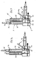
- the control device 6 is preferably designed as a rotary valve control, as shown in FIG. 4.
- a control block 6a with connecting lines 6b a rod-shaped rotary valve 6c is inserted, on its circumference connecting channels 6c 'for connecting and disconnecting the lines 6b are formed.
- the rod-shaped rotary valve 6 c is covered by a cover 6 d with a corresponding semicircular groove held by means of screws with the control block 6a connected is.
- a U-shaped component (Figure 4e) is on the control block 6a mounted in the connection holes 6e 'are formed for connecting lines through which Aspirated medium and discharged again after the pumping.
- a control bracket 6f fixed with a fork at the free end, which passes through a recess 6d 'in the cover 6d protrudes (Fig. 4a and 4c).
- This control bar 6f protrudes through an opening the base plate 1 and is connected to a pin 9e of a U-shaped reversing bracket 9 in Intervention, which will be explained in more detail with reference to FIGS. 2 and 3.
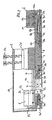
- the two piston slides 5 and 5 ' are provided with a clamping jaw 5c and 5c', respectively. provided, which projects through an opening 1a of the base plate 1 and with a metal band. 7 is firmly connected, which is guided around two spaced rollers in the form of rolling bearings 7a and 7a ' is, in a recess on the back of the base plate 1 in Rollenhaltem 7b, 7b 'stored are.
- the roll holder 7b is fixedly connected to the base plate 1 by a screw 7c, while the roll holder 7b 'by a screw 7c' relative to the base plate 1 in the longitudinal direction the metal band 7 is adjustable so that the belt 7 taut around the two rollers or rolling bearings 7a and 7a 'can be stretched.
- a metal strip 7 may also be a timing belt or the like can be provided.
- the jaw 5c 'of the piston carriage 5' not shown in FIG Section shown. It is at the in Fig. 2 upper strand of the two rollers 7a, 7a 'out Bandes 7 attached while the jaw 5 c is attached to the lower run of the belt 7.
- the clamping jaw 5c ' is provided with a blind bore 5d into which a drive dome 13 (FIG. 8) is inserted.
- a drive means engages the jaw 5c 'in the direction of the belt 7 back and forth reciprocated.
- the two piston slides 5 and 5 ' are reciprocated in opposite directions through the metal strip 7, whereby the one group of three pistons performs, for example, a pumping movement, while the other group of three pistons performs a suction movement.
- the jaw 5c ' engages in a slot 8a of a connecting rod 8, which on the back the base plate 1 is guided in a recess and with the opposite end with a slider 8b is fixed, which is displaceably guided on a guide rod 8c, which is fixedly arranged in a recess of the base plate 1.
- a Slider 8d With the slider 8b is a Slider 8d firmly connected, which at the two ends a bifurcated section with a Inclined surface 8e, which cooperates with a spring-loaded catch 10 or 10a, that during the sliding movement of the slider 8d in Fig. 3 to the right, the latch 10a pushed back and the leg 9a of the reverser bracket 9 is released, the by a Spring 9c 'is biased in the direction to the right.
- control bar 9 moves to the right under entrainment the control bar 6f, which engages with the pin 9e of the reversing bracket 9.
- the rotary valve 6c is rotated by relaxing the spring 9c 'in a position in which is switched from suction to conveying or vice versa.
- the left leg 9b of the reversing bow 9 in FIGS. 2 and 3 acts with a limit switch 16 preferably in the form of an inductive pickup together, the two positions 16a and 16b of the leg 9b notes.
- Via electrical lines 16c, 16c ' is a corresponding Signal to a drive motor 13 f (Fig. 8) forwarded so that this direction of rotation reverses to drive movement over the drive mandrel 13 engaging the jaw 5c ' of the piston slide 5 'in the figures to the left while at the same time the metal strip 7 of the piston slide 5 is moved to the right to perform a Pumphub.
- the jaw 5 c 'in Fig. 2 and 3 is first moved to the left without the Connecting rod 8 is taken, because the jaw 5 c 'in the slot 8 a of Connecting rod 8 moves.
- the connecting rod 8 in Fig. 2 and 3 moved to the left becomes.
- Fig. 5 and 5a show schematically with the reference numerals used in Figs. 2 and 3 the Reversing device with the control device. Due to the reproduced embodiment results a switching time of 2 ms on the rotary valve 6c, at the same time the direction of rotation of Drive motor 13f is switched over the inductive pickup 16.
- the inclined surfaces 8e formed directly on the connecting rod 8. In the slot 8a and the drive dome 13 can intervene to the Um Kunststoff ceremonies directly trigger.
- Fig. 6 shows schematically the suction and pressure stroke of the connected to the piston carriage Piston of two syringes 3 and 3 'in conjunction with the control device 6 and the rotary valve 6c.
- a shut-off vent rotary valve is shown in Fig. 6, whose Function will be explained in more detail with reference to FIG. 7.
- Fig. 6 the vent rotary valve 11 is shown in its closed position.
- Fig. 4 shows, the venting rotary valve 11 in the same manner as the control rotary valve 6c integrated into the control device 6. He juts over one end of the controller 6 before and is connected to a lever 11 a, so that it can be converted by hand.
- a bleed syringe 12 to a connecting line 11b of the control device 6 connected, in which the venting rotary valve 11 is arranged.
- This connection cable 11b is connected to the leads 6b leading to the syringe barrels 3c, in which schematic representation of FIGS. 6 and 7 only one of the leading to the lines 6b Connecting lines 11b is shown.
- the individual are successively Piston of the syringe 3 in the vertical position of the metering pump of FIG. 1 at the top of the Pulled out syringe barrel, as shown in FIG. 7 shows schematically.
- the venting syringe 12 is connected by switching the venting rotary valve 11, while the rotary valve 6c connects the outlet of the syringe 3 with the delivery side.
- the rotary valve 6c connects the outlet of the syringe 3 with the delivery side.
- medium is pressed into the syringe 3 through the venting syringe, with filled syringe 3 at its upper open end by the surface tension of the medium forms a dome M.
- the described metering pump operates by the drive motor 13f described below pulsation-free and continuous and can be used for a wide range of media up to 10 bar be used, the respective medium is transported gently.
- Flow rates are promoted, for example, within an hour a stroke of only about 2/10 mm can be performed.
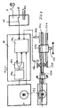
- Fig. 8 shows a play-free Driving the engaging in the dargestellen embodiment in the jaw 5c ' Drive dome 13.
- the drive motor generates a drive movement corresponding to a harmonic sinusoid. This contributes significantly to the generation of a pulsation-free promotion.
- play-free and rigid drive train with a play-free and torsionally stiff coupling 13e, one backlash-free and rigid bearing 13d, a gradient-stable and kink-resistant drive spindle 13c, a play-free spindle nut 13a and a play-free spindle nut guide 13b (Fig. 8).
- the achievable flow of the metering pump results from the piston area of the respective Spraying 3 and the conveying speed of the piston, with delivery volumes in the range from 80 n1 / h to 101 / h are achievable.
- the described metering pump with three syringes per delivery or suction stroke can take up to three Pump or mix different fluids in a definable ratio. Even if the Metering pump is designed for small flow rates, with a larger flow rate through Increasing the conveying speed of the piston rinsing by means of another medium be performed.
- Fig. 8 shows schematically the electrical or electronic control of the metering pump described with a motor electronics 14, a power stage 14a, a controller 14b and a Control unit 14 c, which receives the signals from the non-contact end position sensor 16 receives and for switching the direction of rotation to the motor 13f knower concerns.
- a Operating mode selector reproduced that a control or setpoint via a Potentiometer P, an analog signal A or via an interface RS allows, through the one Control via a PC or a corresponding software is possible.
- By software is a free parameterization of the flow and the flow rate possible.
- the drive unit shown schematically in FIG. 8 can be in a separate, block-shaped Be housed component from which only the drive pin 13 protrudes, with the Dosing pump is coupled.
- Dosing pump clamping jig or the like connecting elements can be provided preferably in conjunction with dowel pins between pump and drive unit, so that the Drive unit occupies a predetermined position relative to the metering pump.
- the dosing pump itself is constructed so that it can be sterilized in a few simple steps Cleaning can be disassembled.
- the clamping device 2 and the control device 6 be secured by screws to the base plate 1.
- the metering pump is expediently mounted on an L-shaped carrier T. mounted, wherein the metering pump is inserted between two support plates Tp. Side to one the support plates are the mode selector switch 15 and a knob 20 for adjustment the piston speed and the like provided.
- the in the dimensions relatively small Dosing pump can be positioned by means of the carrier T on a laboratory bench or the like become.
- the drive unit can in this case with the base plate 1 fixed between the carrier plates Tp be mounted while the medium-carrying control device 6, for example by means of Removable screws, so that all fluid-carrying components for cleaning and Sterilization can be quickly removed.
- the syringes not shown in FIG Be via unillustrated lines and connection plugs with the appropriate Holes in the control device 6 connected. On the front side of the control device 6 holes are provided for the connection lines.
- three pistons each are connected to a precisely working, play-free linear drive system coupled, with all the pistons synchronized move without a stroke difference between the individual pistons occurs. It can commercially available syringes in the diameter range of about 0.7 to 23 mm are used.
- all components of the metering pump coming into contact with the medium are off electrically insulating material or electrically insulated, so no electrical Potential of the medium can be derived, for example, if promoted ionized medium becomes.
Landscapes
- Engineering & Computer Science (AREA)
- Mechanical Engineering (AREA)
- General Engineering & Computer Science (AREA)
- Infusion, Injection, And Reservoir Apparatuses (AREA)
- Reciprocating Pumps (AREA)
- Automatic Analysis And Handling Materials Therefor (AREA)
Abstract
Die Erfindung betrifft eine Dosierpumpe, umfassend eine auf einer Basisplatte (1) angebrachte Klemmeinrichtung (2) für Spritzen (3), deren Kolben an auf der Basisplatte verschiebbaren Betätigungselementen (5) einhängbar bzw. befestigbar sind, wobei den Betätigungselementen (5) gegenüberliegend auf der Basisplatte eine Steuereinrichtung (6) angeordnet ist, mit der die Spritzenzylinder der Spritzen (3) verbunden sind und die zum Umsteuern von Saug- und Druckleitungen mit einer Antriebseinrichtung (13) gekoppelt ist, welche die Betätigungselemente (5, 5') für wenigstens zwei Spritzen (3, 3') gegenläufig hin- und herbewegt.The invention relates to a metering pump comprising a clamping device (2) for syringes (3) mounted on a base plate (1), the pistons of which can be suspended or fastened to actuating elements (5) displaceable on the base plate, the actuating elements (5) lying opposite one another the base plate, a control device (6) is arranged, with which the syringe cylinders of the syringes (3) are connected and which is coupled for reversing suction and discharge lines with a drive device (13), which the actuating elements (5, 5 ') for at least two syringes (3, 3 ') reciprocated back and forth.
Description
Die Erfindung betrifft eine Dosierpumpe insbesondere für sehr kleine Liefermengen.The invention relates to a metering pump, in particular for very small quantities.
Durch die Erfindung soll eine Dosierspumpe vorgeschlagen werden, die einen einfachen Aufbau hat und bei der übliche Spritzen als Pumpelemente verwendet werden können.The invention provides a dosing pump to be proposed, which has a simple structure has and can be used in conventional syringes as pumping elements.
Dies wird erfindungsgemäß durch eine Dosierpumpe nach dem Anspruch 1 erreicht. In der
Klemmeinrichtung können Spritzen mit verschiedenen Kolbendurchmessem eingesetzt werden
und durch die Anordnung der Elemente der Dosierpumpe auf einer Basisplatte ergibt sich ein
einfacher Aufbau.This is inventively achieved by a metering pump according to
Eine beispielsweise Ausführungsform der Erfindung wird nachfolgend anhand der Zeichnung näher erläutert. Es zeigen
- Fig. 1
- eine perspektivische Vorderansicht der Dosierpumpe,
- Fig. 2
- eine Ansicht der Rückseite der Dosierpumpe,
- Fig. 3
- einen Längsschnitt durch die Dosierpumpe längs der Linie A-A in Fig. 2,
- Fig. 4
- die Steuereinrichtung in verschiedenen Ansichten,
- Fig. 5
- in schematischer Darstellung das Zusammenwirken zwischen Umsteuereinrichtung und Steuereinrichtung,
- Fig. 6
- in schematischer Darstellung die Steuereinrichtung mit einer Entlüftungsspritze,
- Fig. 7
- in schematischer Darstellung die Funktion der Entlüftungsspritze, und
- Fig. 8
- eine schematische Ansicht des Antriebsteils der Dosierpumpe.
- Fig. 1
- a perspective front view of the metering pump,
- Fig. 2
- a view of the back of the metering pump,
- Fig. 3
- a longitudinal section through the metering pump along the line AA in Fig. 2,
- Fig. 4
- the control device in different views,
- Fig. 5
- a schematic representation of the interaction between the reversing device and the control device,
- Fig. 6
- a schematic representation of the control device with a vent syringe,
- Fig. 7
- a schematic representation of the function of the venting syringe, and
- Fig. 8
- a schematic view of the drive part of the metering pump.
Fig. 1 zeigt eine Vorderansicht der Dosierpumpe ohne die darin eingesetzten Spritzen, die in Fig.
1a schematisch wiedergegeben sind. Auf einer etwa rechteckigen Basisplatte 1 (Fig. 2 und 3) ist
etwa in der Mitte eine Klemmeinrichtung 2 fest angebracht, auf deren Vorderseite Klemmschrauben
2a für die in der Klemmeinrichtung einzusetzenden Spritzen 3 bzw. deren Zylinder 3c
vorgesehen sind. Bei dem dargestellten Ausführungsbeispiel sind sechs Klemmschrauben 2a für
sechs Spritzen 3 vorgesehen. Auf der an der Basisplatte 1 anliegenden Seite der etwa kastenförmig
und auf beiden Seiten offenen Klemmeinrichtung 2 sind sechs V-förmige Nuten 2b ausgebildet,
wobei jeweils ein Spritzenzylinder in eine solche V-förmige Nut 2b eingelegt wird. Diesen
Nuten 2b gegenüberliegend ist ein längliches Klemmstück 2c mit einer entsprechenden V-förmigen
Nut angeordnet, das mit der zugeordneten Klemmschraube 2a in Verbindung steht und
durch diese in Richtung auf die V-Nut 2b vor und zurück bewegt werden kann, um einen Spritzenzylinder
einzuklemmen bzw. freizugeben, wie dies auch Fig. 3 zeigt.FIG. 1 shows a front view of the metering pump without the syringes inserted therein, which are shown in FIG.
1a are shown schematically. On an approximately rectangular base plate 1 (Figures 2 and 3)
approximately in the middle of a
Auf zwei parallel zueinander angeordneten Führungsstangen 4 und 4' an der Basisplatte 1 sind
zwei Kolbenschlitten 5 und 5' verschiebbar, die eine Quernut 5a und U-förmige Haltegabeln 5b
aufweisen, wobei in die Quernut 5a eine Drückerplatte 3a der Kolbenstange 3b einer Spritze 3
so eingesetzt wird, wie Fig. 1a schematisch zeigt, dass die Kolbenstange 3b in einem der gabelförmigen
Halter 5b liegt. Bei 5c sind Klemmschrauben wiedergegeben (Fig. 3), durch die eine
Drückerplatte 3a eines Kolbens spielfrei in der Quernut 5a festgeklemmt werden kann. Bei dem
dargestellten Ausführungsbeispiel werden die Kolbenstangen von drei Spritzen 3 mit dem
Kolbenschlitten 5 und drei Spritzen 3 mit dem Kolbenschlitten 5' auf diese Weise verbunden.On two mutually parallel guide rods 4 and 4 'on the
In Fig. 3 ist ein vorzugsweise transparentes Gehäuseteil 1b wiedergegeben, das die Kolbenschlitten abdeckt.In Fig. 3, a preferably transparent housing part 1b is reproduced, which is the piston slide covers.
Auf der gegenüberliegenden Seite der Klemmeinrichtung 2 ist eine Steuereinrichtung 6 an der
Basisplatte 1 angebracht, mit der die einzelnen Spritzen 3 über vorzugsweise flexible
Schlauchleitungen 3d verbunden sind, wie Fig. 1a zeigt. Die Steuereinrichtung 6 ist vorzugsweise
als Drehschiebersteuerung ausgebildet, wie sie Fig. 4 zeigt. In eine etwa halbkreisförmige Nut
eines Steuerblocks 6a mit Verbindungsleitungen 6b ist ein stabförmiger Drehschieber 6c eingesetzt,
auf dessen Umfang Verbindungskanäle 6c' zum Verbinden und Unterbrechen der Leitungen
6b ausgebildet sind. Der stabförmige Drehschieber 6c wird durch eine Abdeckung 6d mit einer
entsprechenden halbkreisförmigen Nut gehalten, die mittels Schrauben mit dem Steuerblock 6a
verbunden ist. Bei 6e ist ein im Querschnitt U-förmiges Bauteil (Fig. 4e) an dem Steuerblock 6a
angebracht, in dem Anschlussbohrungen 6e' für Anschlussleitungen ausgebildet sind, durch die
Medium angesaugt und nach dem Pumpvorgang wieder abgegeben wird. An dem Drehschieber
6c ist ein Steuerbügel 6f mit einer Gabel am freien Ende befestigt, der durch eine Ausnehmung
6d' in der Abdeckung 6d ragt (Fig. 4a und 4c). Dieser Steuerbügel 6f ragt durch eine Durchbrechung
der Basisplatte 1 und steht mit einem Zapfen 9e eines U-förmigen Umsteuerbügels 9 in
Eingriff, der nachfolgend anhand der Fig. 2 und 3 näher erläutert wird.On the opposite side of the
Wie Fig. 3 zeigt, sind die beiden Kolbenschlitten 5 und 5' mit einer Klemmbacke 5c bzw. 5c'
versehen, die durch eine Durchbrechung 1a der Basisplatte 1 ragt und mit einem Metallband 7
fest verbunden ist, das um zwei beabstandete Rollen in Form von Wälzlagern 7a und 7a' geführt
ist, die in einer Ausnehmung auf der Rückseite der Basisplatte 1 in Rollenhaltem 7b, 7b' gelagert
sind. Der Rollenhalter 7b ist durch eine Schraube 7c mit der Basisplatte 1 fest verbunden,
während der Rollenhalter 7b' durch eine Schraube 7c' relativ zur Basisplatte 1 in Längsrichtung
des Metallbandes 7 einstellbar ist, damit das Band 7 straff um die beiden Rollen bzw. Wälzlager
7a und 7a' gespannt werden kann. Anstelle eines Metallbandes 7 kann auch ein Zahnriemen oder
dergleichen vorgesehen werden.As shown in FIG. 3, the two
In Fig. 3 ist die Klemmbacke 5c' des in Fig. 3 nicht wiedergegebenen Kolbenschlittens 5' im
Schnitt dargestellt. Sie ist an dem in Fig. 2 oberen Trum des um die beiden Rollen 7a, 7a' geführten
Bandes 7 befestigt, während die Klemmbacke 5c am unteren Trum des Bandes 7 befestigt ist.
Die Klemmbacke 5c' ist mit einer Sackbohrung 5d versehen, in die ein Antriebsdom 13 (Fig. 8)
einer Antriebseinrichtung eingreift, die die Klemmbacke 5c' in Richtung des Bandes 7 hin- und
herbewegt. Durch die Antriebsbewegung der Klemmbacke 5c' in Fig. 3 nach links wird gleichzeitig
und synchron die Klemmbacke 5c und damit der Kolbenschlitten 5 nach rechts bewegt.
Durch die Hin- und Herbewegung des in die Sackbohrung 5d eingreifenden Antriebsdoms 13
werden die beiden Kolbenschlitten 5 und 5' gegenläufig durch das Metallband 7 hin- und herbewegt,
wodurch die eine Gruppe von drei Kolben beispielsweise eine Pumpbewegung ausführt,
während die andere Gruppe von drei Kolben eine Saugbewegung ausführt.In FIG. 3, the
Die Klemmbacke 5c' greift in ein Langloch 8a einer Verbindungsstange 8 ein, die auf der Rückseite
der Basisplatte 1 in einer Ausnehmung geführt und mit dem gegenüberliegenden Ende mit
einem Gleitstück 8b fest verbunden ist, das auf einer Führungsstange 8c verschiebbar geführt ist,
die in einer Ausnehmung der Basisplatte 1 fest angeordnet ist. Mit dem Gleitstück 8b ist ein
Schieber 8d fest verbunden, der an den beiden Enden einen gabelförmigen Abschnitt mit einer
Schrägfläche 8e aufweist, die mit einer federbeaufschlagten Raste 10 bzw. 10a derart zusammenwirkt,
dass bei der Verschiebebewegung des Schiebers 8d in Fig. 3 nach rechts die Raste 10a
zurückgedrückt und der Schenkel 9a des Umsteuerbügels 9 frei gegeben wird, der durch eine
Feder 9c' in Richtung nach rechts vorgespannt ist. Hierdurch wird der in Fig. 3 mit dem linken
Schenkel 9b an der Basisplatte 1 anliegende Steuerbügel 9 nach rechts bewegt unter Mitnahme
des Steuerbügels 6f, der mit dem Zapfen 9e des Umsteuerbügels 9 in Eingriff steht. Auf diese
Weise wird der Drehschieber 6c durch Entspannen der Feder 9c' in eine Stellung gedreht, in der
von Ansaugen auf Fördern bzw. umgekehrt umgeschaltet wird.The
Der in Fig. 2 und 3 linke Schenkel 9b des Umsteuerbügels 9 wirkt mit einem Endschalter 16
vorzugsweise in der Form eines induktiven Aufnehmers zusammen, der zwei Stellungen 16a und
16b des Schenkels 9b feststellt. Über elektrische Leitungen 16c, 16c' wird ein entsprechendes
Signal an einen Antriebsmotor 13f (Fig. 8) weitergeleitet, damit dieser seine Drehrichtung
umkehrt, um über den in die Klemmbacke 5c' eingreifenden Antriebsdorn 13 eine Antriebsbewegung
des Kolbenschlittens 5' in den Figuren nach links auszuführen, während gleichzeitig über
das Metallband 7 der Kolbenschlitten 5 nach rechts bewegt wird, um einen Pumphub auszuführen.The left leg 9b of the reversing
Hierbei wird die Klemmbacke 5c' in Fig. 2 und 3 zunächst nach links bewegt, ohne dass die
Verbindungsstange 8 mitgenommen wird, weil sich die Klemmbacke 5c' in dem Langloch 8a der
Verbindungsstange 8 bewegt. In einem vorgegebenen Abstand vor der linken Endstellung des
Kolbenschlittens 5' kommt die vom Antriebsmotor angetriebene Klemmbacke 5c' am Ende des
Langlochs 8a zum Anliegen, so dass die Verbindungsstange 8 in Fig. 2 und 3 nach links verschoben
wird. Bei der vorausgegangenen Verschiebung des Umsteuerbügels 9 nach rechts ist der
Schenkel 9b vor die Raste 10 verschoben worden, so dass diese den Umsteuerbügel 9 in der
rechten Stellung hält und bei der Verschiebebewegung des Gleitstücks 8b nach links zunächst
die Feder 9c gegen den Schenkel 9b zusammengedrückt und gespannt wird, während die rechte
Feder 9c' entspannt bleibt. Sobald die Schrägfläche 8e des Schiebers 8d bei der Bewegung nach
links die Raste 10 erreicht und zurückdrückt, wird der linke Schenkel 9b des Umsteuerbügels 9
freigegeben, so dass die Vorspannung der Feder 9c den Umsteuerbügel 9 nach links drückt,
wodurch über den Zapfen 9e der Drehschieber 6c in die Umschaltstellung verdreht wird.In this case, the
Fig. 5 und 5a zeigen schematisch mit den in den Fig. 2 und 3 verwendeten Bezugszeichen die
Umsteuereinrichtung mit der Steuereinrichtung. Durch die wiedergegebene Ausgestaltung ergibt
sich eine Umschaltzeit von 2 ms am Drehschieber 6c, wobei gleichzeitig die Drehrichtung des
Antriebsmotors 13f über den induktiven Aufnehmer 16 umgeschaltet wird. Bei der schematischen
Darstellung in Fig. 5 sind die Schrägflächen 8e unmittelbar an der Verbindungsstange 8 angeformt.
In das Langloch 8a kann auch der Antriebsdom 13 eingreifen, um die Umsteuerbewegung
direkt auszulösen.Fig. 5 and 5a show schematically with the reference numerals used in Figs. 2 and 3 the
Reversing device with the control device. Due to the reproduced embodiment results
a switching time of 2 ms on the
Fig. 6 zeigt schematisch den Saug- und Druckhub der mit den Kolbenschlitten verbundenen
Kolben zweier Spritzen 3 und 3' in Verbindung mit der Steuereinrichtung 6 und dem Drehschieber
6c. Bei 11 ist in Fig. 6 ein abgesperrter Entlüftungs-Drehschieber wiedergegeben, dessen
Funktion anhand von Fig. 7 näher erläutert wird.Fig. 6 shows schematically the suction and pressure stroke of the connected to the piston carriage
Piston of two
In Fig. 6 ist der Entlüftungs-Drehschieber 11 in seiner abgesperrten Stellung wiedergegeben. Wie
Fig. 4 zeigt, ist der Entlüftungs-Drehschieber 11 in der gleichen Weise wie der Steuer-Drehschieber
6c in die Steuereinrichtung 6 integriert. Er ragt über ein Ende der Steuereinrichtung
6 vor und ist mit einem Hebel 11 a verbunden, damit er von Hand umgestellt werden kann. In den
Fig. 6 und 6a ist eine Entlüftungsspritze 12 an eine Anschlussleitung 11b der Steuereinrichtung
6 angeschlossen, in der der Entlüftungs-Drehschieber 11 angeordnet ist. Diese Anschlussleitung
11b ist mit den zu den Spritzenzylindern 3c führenden Leitungen 6b verbunden, wobei in der
schematischen Darstellung der Fig. 6 und 7 jeweils nur eine der zu den Leitungen 6b führenden
Anschlussleitungen 11b wiedergegeben ist.In Fig. 6, the
Um die Dosierpumpe vor Betriebsaufnahme zu entlüften, werden nacheinander die einzelnen
Kolben der Spritzen 3 in der vertikalen Stellung der Dosierpumpe nach Fig. 1 oben aus dem
Spritzenzylinder herausgezogen, wie dies Fig. 7 schematisch zeigt. An die zu entlüftende Spritze
3 wird die Entlüftungsspritze 12 durch Umschalten des Entlüftungs-Drehschiebers 11 angeschlossen,
während der Drehschieber 6c den Ausgang der Spritze 3 mit der Förderseite verbindet.
In dieser Stellung wird durch die Entlüftungsspritze 12 Medium in die Spritze 3 eingedrückt,
wobei sich bei gefüllter Spritze 3 an deren oberem offenen Ende durch die Oberflächenspannung
des Mediums eine Kuppe M bildet. Zugleich sammeln sich in dem Medium enthaltene Luftblasen
3o am oberen Ende des Spritzenzylinders 3c, wobei sie durch Klopfen an dem Spritzenzylinder
nach oben entweichen können. Hierauf wird der Kolben auf die Kuppe M des Mediums aufgesetzt
und in den Spritzenzylinder so eingedrückt, dass keine Luftblasen am oberen Ende des
Spritzenzylinders mehr vorhanden sind. Durch weiteres Eindrücken der Entlüftungsspritze 12
werden Luftblasen 3o, die sich in der Leitung 6b der Steuereinrichtung 6 befinden, nach außen
zur Förderseite gedrückt, wie dies durch einen Pfeil in Fig. 7 angedeutet ist. Zum Entlüften der
in Fig. 7 mit 3' bezeichneten Spritze wird die Entlüftungsspritze 12 mit dem Spritzenzylinder 3c'
verbunden, während dieser über den Drehschieber 6c mit dem Ausgang bzw. der Förderseite
verbunden wird. Hierauf wird in gleicher Weise durch Einführen von Medium durch die Entlüftungsspritze
12 der Spritzenzylinder 3c' gefüllt, wobei der Kolben über die Kolbenstange 3b' aus
dem Spritzenzylinder herausgezogen wird, damit Luftblasen 3o entweichen können. Auf die sich
durch Oberflächenspannung des Mediums bildende Kuppe M wird der Kolben derart aufgesetzt
und in den Spritzenzylinder eingedrückt, dass in diesem Bereich keine Luftblasen mehr vorhanden
sind. Durch weiteres Einpressen von Medium durch die Entlüftungsspritze 12 werden
Luftblasen 3o aus der Leitung 6b' nach außen befördert.To bleed the dosing pump before starting operation, the individual are successively
Piston of the
Die beschriebene Dosierpumpe arbeitet durch den nachfolgend beschriebenen Antriebsmotor 13f pulsationsfrei und kontinuierlich und kann für verschiedenste zu fördernde Medien bis zu 10 bar eingesetzt werden, wobei das jeweilige Medium schonend transportiert wird.The described metering pump operates by the drive motor 13f described below pulsation-free and continuous and can be used for a wide range of media up to 10 bar be used, the respective medium is transported gently.
Durch den spielfrei und steif ausgestalteten Kraftstrang der Dosierpumpe können minimale
Fördermengen gefördert werden, wobei beispielsweise innerhalb einer Stunde ein Hub von nur
etwa 2/10 mm ausgeführt werden kann. Durch die Verbindung der Kolbenschlitten 5 und 5' über
Klemmbacken 5c mit dem spielfrei um die Wälzlager 7a geführten Metallband 7 wird in diesem
Bereich der Antriebseinrichtung eine spielfreie Ausgestaltung erreicht. Fig. 8 zeigt einen spielfreien
Antrieb des bei dem dargestellen Ausführungsbeispiel in die Klemmbacke 5c' eingreifenden
Antriebsdoms 13. Dieser ist an einer Spindelmutter 13a angebracht, die einerseits auf einer
Führungsstange 13b spielfrei geführt ist, beispielsweise durch eine vorgespannte Kugelführung,
und andererseits durch eine steigungstreue Präzisionsspindel 13c angetrieben wird, wobei in der
spielfrei eingestellten Spindelmutter eine Nachstelleinrichtung vorgesehen ist. Bei 13d ist eine
spielfrei vorgespannte Lagerung der Präzisionsspindel 13c wiedergegeben, die über eine spielfrei
und verdrehsteife Ausgleichskupplung 13e mit dem Antriebsmotor 13f verbunden ist, der
vorzugsweise als elektronisch kommutierter Gleichstrom-Servomotor mit nahezu idealer Sinusgenerierung
für einen pulsationsfreien Betrieb ausgebildet ist.Due to the backlash-free and stiff designed power train of the metering pump minimum
Flow rates are promoted, for example, within an hour a stroke of only
about 2/10 mm can be performed. By connecting the
Der Antriebsmotor erzeugt eine Antriebsbewegung entsprechend einer harmonischen Sinuskurve.
Dies trägt wesentlich zur Erzeugung einer pulsationsfreien Förderung bei. Hinzu kommt ein
spielfreier und steifer Antriebsstrang mit einer spielfreien und verdrehsteifen Kupplung 13e, einer
spielfreien und steifen Lagerung 13d, einer steigungstreuen und knicksteifen Antriebsspindel 13c,
einer spielfreien Spindelmutter 13a und einer spielfreien Spindelmutterführung 13b (Fig. 8). The drive motor generates a drive movement corresponding to a harmonic sinusoid.
This contributes significantly to the generation of a pulsation-free promotion. Add to that
play-free and rigid drive train with a play-free and torsionally stiff coupling 13e, one
backlash-free and
Der erzielbare Förderstrom der Dosierpumpe ergibt sich aus der Kolbenfläche der jeweiligen
Spritzen 3 und der Fördergeschwindigkeit von deren Kolben, wobei Fördervolumina im Bereich
von 80 n1/h bis 101/h erzielbar sind.The achievable flow of the metering pump results from the piston area of the
Die beschriebene Dosierpumpe mit drei Spritzen pro Förder- bzw. Saughub kann bis zu drei verschiedene Fluide in einem festlegbaren Verhältnis pumpen bzw. mischen. Auch wenn die Dosierpumpe auf kleine Fördermengen ausgelegt ist, kann mit einer größeren Fördermenge durch Erhöhung der Fördergeschwindigkeit der Kolben eine Spülung mittels eines anderen Mediums durchgeführt werden.The described metering pump with three syringes per delivery or suction stroke can take up to three Pump or mix different fluids in a definable ratio. Even if the Metering pump is designed for small flow rates, with a larger flow rate through Increasing the conveying speed of the piston rinsing by means of another medium be performed.
Da für die Umschaltung zwischen Saug- und Förderhub keine Ventile erforderlich sind, kann eine Umschaltung im Bereich von kleiner 2 ms durch den Drehschieber erreicht werden, wobei sich durch die Drehschieberwelle eine mengenneutrale Umschaltung ergibt.Since no valves are required for switching between suction and delivery, a Switching in the range of less than 2 ms can be achieved by the rotary valve, with through the rotary valve shaft results in a volume-neutral switching.
Fig. 8 zeigt schematisch die elektrische bzw. elektronische Steuerung der beschriebenen Dosierpumpe
mit einer Motorelektronik 14, die eine Leistungsstufe 14a, einen Regler 14b und eine
Steuereinheit 14c aufweist, welche die Signale von dem berührungslosen Endlagengeber 16
aufnimmt und zum Umschalten der Drehrichtung an den Motor 13f weitergibt. Bei 15 ist ein
Betriebsartenwahlschalter wiedergegeben, der eine Ansteuerung bzw. Sollwertvorgabe über ein
Potentiometer P, ein Analogsignal A oder über eine Schnittstelle RS ermöglicht, durch die eine
Ansteuerung über einen PC bzw. eine entsprechende Software möglich ist. Mittels Software ist
eine freie Parametrierung des Förderstroms und der Fördermenge möglich.Fig. 8 shows schematically the electrical or electronic control of the metering pump described
with a
Die in Fig. 8 schematisch wiedergegebene Antriebseinheit kann in einem gesonderten, blockförmigen
Bauteil untergebracht sein, aus dem lediglich der Antriebsdorn 13 vorsteht, der mit der
Dosierpumpe gekoppelt wird. Zum schnellen Verbinden und Lösen von Antriebseinheit und
Dosierpumpe können Spannbügel oder dergleichen Verbindungselemente vorgesehen werden,
vorzugsweise in Verbindung mit Passstiften zwischen Pumpen- und Antriebseinheit, damit die
Antriebseinheit eine vorgegebene Position relativ zur Dosierpumpe einnimmt.The drive unit shown schematically in FIG. 8 can be in a separate, block-shaped
Be housed component from which only the
Die Dosierpumpe selbst ist so aufgebaut, dass sie mit wenigen Handgriffen zum Sterilisieren und
Reinigen zerlegt werden kann. Beispielsweise kann die Klemmeinrichtung 2 und die Steuereinrichtung
6 mittels Schrauben an der Basisplatte 1 befestigt sein. The dosing pump itself is constructed so that it can be sterilized in a few simple steps
Cleaning can be disassembled. For example, the
Es sind verschiedene Abwandlungen der beschriebenen Bauform möglich. So kann anstelle der
Klemmeinrichtung 2 auch eine feste Anbringung der Spritzen 3 in der Weise vorgesehen werden,
dass diese in einem Bauteil eingesetzt sind, das an der Basisplatte 1 angeschraubt ist. Auf diese
Weise kann dieses Bauteil mit den Spritzen leicht abgenommen und zum Sterilisieren und
Reinigen getrennt gehandhabt werden.There are various modifications of the described design possible. So instead of the
Anstelle der beschriebenen dreiflutigen Ausgestaltung der Dosierpumpe durch Dreiergruppen von
Spritzen 3 kann auch eine andere Gruppierung von Spritzen an den einzelnen Kolbenschlitten
vorgesehen werden, um eine vorgegebene mehrflutige Ausgestaltung zu erhalten. Die Kolbendurchmesser
der Spritzen können unterschiedlich ausgelegt werden, um ein gewünschtes Mischungsverhältnis
bei einem Pumpvorgang zu erhalten.Instead of the described dreiflutigen embodiment of the metering pump by triplets of
Wie Fig. 1 zeigt, wird die Dosierpumpe zweckmäßigerweise auf einem L-förmigen Träger T
montiert, wobei die Dosierpumpe zwischen zwei Trägerplatten Tp eingesetzt ist. Seitlich an einer
der Trägerplatten sind der Betriebsartenwahlschalter 15 und ein Einstellknopf 20 zum Einstellen
der Kolbengeschwindigkeit und dergleichen vorgesehen. Die in den Abmessungen relativ kleine
Dosierpumpe kann mittels des Trägers T auf einem Labortisch oder dergleichen positioniert
werden. Die Antriebseinheit kann hierbei mit der Basisplatte 1 fest zwischen den Trägerplatten
Tp montiert sein, während die mediumführende Steuereinrichtung 6 beispielsweise mittels
Schrauben abnehmbar angebracht ist, damit alle mediumführenden Bauteile zum Reinigen und
Sterilisieren schnell abgenommen werden können. Die in Fig. 1 nicht wiedergegebenen Spritzen
werden über nicht dargestellte Leitungen und Verbindungsstöpsel mit den entsprechenden
Bohrungen in der Steuereinrichtung 6 verbunden. Auf der Vorderseite der Steuereinrichtung 6
sind Bohrungen für die Anschlussleitungen vorgesehen.As shown in FIG. 1, the metering pump is expediently mounted on an L-shaped carrier T.
mounted, wherein the metering pump is inserted between two support plates Tp. Side to one
the support plates are the
Die vertikale Positionierung der Dosierpumpe auf dem Träger T mit oben liegenden Kolbenstangen
3b erleichtert das Entlüften der einzelnen Spritzen 3.The vertical positioning of the dosing pump on the support T with
Bei der dargestellten dreiflutigen Dosierpumpe sind jeweils drei Kolben an ein präzise arbeitendes, spielfreies Linear-Antriebssystem gekoppelt, wobei sich alle Kolben synchron zueinander bewegen, ohne dass ein Hubunterschied zwischen den einzelnen Kolben auftritt. Es können marktübliche Spritzen im Durchmesserbereich von ca. 0,7 bis 23 mm eingesetzt werden. In the illustrated three-flow metering pump, three pistons each are connected to a precisely working, play-free linear drive system coupled, with all the pistons synchronized move without a stroke difference between the individual pistons occurs. It can commercially available syringes in the diameter range of about 0.7 to 23 mm are used.
Vorzugsweise sind alle mit Medium in Berührung kommenden Bauteile der Dosierpumpe aus elektrisch isolierendem Material bzw. elektrisch isoliert ausgebildet, damit kein elektrisches Potential des Mediums abgeleitet werden kann, wenn beispielsweise ionisiertes Medium gefördert wird.Preferably, all components of the metering pump coming into contact with the medium are off electrically insulating material or electrically insulated, so no electrical Potential of the medium can be derived, for example, if promoted ionized medium becomes.
Claims (10)
Applications Claiming Priority (2)
| Application Number | Priority Date | Filing Date | Title |
|---|---|---|---|
| DE10346341A DE10346341A1 (en) | 2003-10-06 | 2003-10-06 | Dosierspritzenpumpe |
| DE10346341 | 2003-10-06 |
Publications (2)
| Publication Number | Publication Date |
|---|---|
| EP1522727A2 true EP1522727A2 (en) | 2005-04-13 |
| EP1522727A3 EP1522727A3 (en) | 2009-04-08 |
Family
ID=34306286
Family Applications (1)
| Application Number | Title | Priority Date | Filing Date |
|---|---|---|---|
| EP04023691A Withdrawn EP1522727A3 (en) | 2003-10-06 | 2004-10-05 | Dosing pump |
Country Status (3)
| Country | Link |
|---|---|
| US (1) | US20050106051A1 (en) |
| EP (1) | EP1522727A3 (en) |
| DE (1) | DE10346341A1 (en) |
Families Citing this family (1)
| Publication number | Priority date | Publication date | Assignee | Title |
|---|---|---|---|---|
| WO2013163033A1 (en) * | 2012-04-23 | 2013-10-31 | Siemens Healthcare Diagnostics Inc. | Multi-chamber pump apparatus, systems, and methods |
Family Cites Families (20)
| Publication number | Priority date | Publication date | Assignee | Title |
|---|---|---|---|---|
| US1966498A (en) * | 1933-05-04 | 1934-07-17 | Gross Louis | Fluid measuring and dispensing apparatus |
| US1996498A (en) * | 1934-06-18 | 1935-04-02 | Young Radiator Co | Heat transfer device |
| DE1814237A1 (en) * | 1968-12-12 | 1970-06-25 | Lissem Peter | Sampling syringe and reagent doser |
| US3554673A (en) * | 1969-01-31 | 1971-01-12 | Sage Instr Inc | Syringe pump |
| US4065230A (en) * | 1975-01-17 | 1977-12-27 | Hart Associates, Inc. | Reciprocating infusion pump and directional adapter set for use therewith |
| US4120202A (en) * | 1977-03-15 | 1978-10-17 | Baxter Travenol Laboratories, Inc. | Positive displacement pump |
| US4196730A (en) * | 1977-08-01 | 1980-04-08 | Wilson Dennis R | Liquid drug dispenser |
| US4288206A (en) * | 1979-08-15 | 1981-09-08 | Tigwell David C | Automatic multiple water sampler |
| US4470431A (en) * | 1982-02-23 | 1984-09-11 | American Hospital Supply Corporation | Syringe valve and clamping mechanism |
| US4652260A (en) * | 1985-03-11 | 1987-03-24 | Strato Medical Corporation | Infusion device |
| US4804368A (en) * | 1986-12-05 | 1989-02-14 | C. R. Bard, Inc. | Battery operated miniature syringe infusion pump and improved halfnut therefor |
| US4976696A (en) * | 1987-08-10 | 1990-12-11 | Becton, Dickinson And Company | Syringe pump and the like for delivering medication |
| DE3817411A1 (en) * | 1988-05-21 | 1989-11-30 | Fresenius Ag | MULTIPLE INFUSION SYSTEM |
| US5176502A (en) * | 1990-04-25 | 1993-01-05 | Becton, Dickinson And Company | Syringe pump and the like for delivering medication |
| US5492535A (en) * | 1994-04-06 | 1996-02-20 | Cordis Corporation | Hand-powered pumping apparatus for perfusion and other fluid catheterization procedures |
| US5814015A (en) * | 1995-02-24 | 1998-09-29 | Harvard Clinical Technology, Inc. | Infusion pump for at least one syringe |
| EP1920718A1 (en) * | 1995-04-20 | 2008-05-14 | ACIST Medical Systems, Inc. | Radiographic contrast material injector |
| US6220487B1 (en) * | 1998-10-16 | 2001-04-24 | Micro Robotics Systems, Inc. | Dispensing apparatus |
| DE19933392A1 (en) * | 1999-07-21 | 2001-02-08 | Butsch Mietservice Gmbh | Dosing unit, esp for liq or paste material, comprises valves and a dosing pump connected to a valve via a pipe. |
| DE10208776A1 (en) * | 2002-02-28 | 2003-09-04 | Muefa Ag | Infusion unit, useful for the administration of infusion liquids to patients, comprises at least two administration devices, which are mounted on the main body of the unit |
-
2003
- 2003-10-06 DE DE10346341A patent/DE10346341A1/en not_active Ceased
-
2004
- 2004-10-05 EP EP04023691A patent/EP1522727A3/en not_active Withdrawn
- 2004-10-05 US US10/957,643 patent/US20050106051A1/en not_active Abandoned
Also Published As
| Publication number | Publication date |
|---|---|
| US20050106051A1 (en) | 2005-05-19 |
| DE10346341A1 (en) | 2005-05-12 |
| EP1522727A3 (en) | 2009-04-08 |
Similar Documents
| Publication | Publication Date | Title |
|---|---|---|
| EP1495782B1 (en) | Tattooing and permanent make-up device | |
| DE2435912C2 (en) | Follow-up pinch valve | |
| DE68907028T2 (en) | MICROBEATER FOR MARKING. | |
| DE1811153A1 (en) | Device for inserting parts in predetermined positions | |
| DE2809846A1 (en) | FILLING DEVICE FOR LIQUID GOODS | |
| EP1848287A1 (en) | Device for processing an edible product | |
| DE3513880A1 (en) | Unit for pressing out plastic compositions | |
| DE2556282C2 (en) | Device for stepless adjustment of two metering pump pistons in opposite directions | |
| EP0314994B1 (en) | Pump arrangement with double pump | |
| EP0208827A1 (en) | Gripper | |
| DE10259565A1 (en) | Pendulum stroke rod bearing for power saw has bearing regions supporting motion setter located in bearing housing part | |
| DE1598332A1 (en) | Gas detonator | |
| DE4235860A1 (en) | Pipe switch | |
| EP1522727A2 (en) | Dosing pump | |
| EP1739434A2 (en) | Multi-channel metering device | |
| DE10059312A1 (en) | Centering device for conveyed goods | |
| DE2146934B2 (en) | Electromechanical lifting device | |
| DE1528419C3 (en) | Liquid pump | |
| DE10191359B4 (en) | medium pump | |
| DE1964263C3 (en) | Lockable indexing gear | |
| DE8423316U1 (en) | Gripping device | |
| DE655928C (en) | Electric resistance butt welding machine, in particular flash welding machine | |
| DE2407964C3 (en) | Device for adjusting the piston stroke of a piston pump | |
| DE202009014160U1 (en) | Slot nozzle device | |
| EP0911615A1 (en) | Volumetric dosing device |
Legal Events
| Date | Code | Title | Description |
|---|---|---|---|
| PUAI | Public reference made under article 153(3) epc to a published international application that has entered the european phase |
Free format text: ORIGINAL CODE: 0009012 |
|
| AK | Designated contracting states |
Kind code of ref document: A2 Designated state(s): AT BE BG CH CY CZ DE DK EE ES FI FR GB GR HU IE IT LI LU MC NL PL PT RO SE SI SK TR |
|
| AX | Request for extension of the european patent |
Extension state: AL HR LT LV MK |
|
| PUAL | Search report despatched |
Free format text: ORIGINAL CODE: 0009013 |
|
| AK | Designated contracting states |
Kind code of ref document: A3 Designated state(s): AT BE BG CH CY CZ DE DK EE ES FI FR GB GR HU IE IT LI LU MC NL PL PT RO SE SI SK TR |
|
| AX | Request for extension of the european patent |
Extension state: AL HR LT LV MK |
|
| AKX | Designation fees paid | ||
| STAA | Information on the status of an ep patent application or granted ep patent |
Free format text: STATUS: THE APPLICATION IS DEEMED TO BE WITHDRAWN |
|
| 18D | Application deemed to be withdrawn |
Effective date: 20091009 |
|
| REG | Reference to a national code |
Ref country code: DE Ref legal event code: 8566 |