EP1522711A2 - Procédure de distribution du propergol dans un boítier de propergol solide et outil à la mise en oeuvre de la procédure - Google Patents
Procédure de distribution du propergol dans un boítier de propergol solide et outil à la mise en oeuvre de la procédure Download PDFInfo
- Publication number
- EP1522711A2 EP1522711A2 EP04104956A EP04104956A EP1522711A2 EP 1522711 A2 EP1522711 A2 EP 1522711A2 EP 04104956 A EP04104956 A EP 04104956A EP 04104956 A EP04104956 A EP 04104956A EP 1522711 A2 EP1522711 A2 EP 1522711A2
- Authority
- EP
- European Patent Office
- Prior art keywords
- locating member
- forming bodies
- casing
- tool
- forming
- Prior art date
- Legal status (The legal status is an assumption and is not a legal conclusion. Google has not performed a legal analysis and makes no representation as to the accuracy of the status listed.)
- Withdrawn
Links
Images


Classifications
-
- F—MECHANICAL ENGINEERING; LIGHTING; HEATING; WEAPONS; BLASTING
- F02—COMBUSTION ENGINES; HOT-GAS OR COMBUSTION-PRODUCT ENGINE PLANTS
- F02K—JET-PROPULSION PLANTS
- F02K9/00—Rocket-engine plants, i.e. plants carrying both fuel and oxidant therefor; Control thereof
- F02K9/08—Rocket-engine plants, i.e. plants carrying both fuel and oxidant therefor; Control thereof using solid propellants
- F02K9/24—Charging rocket engines with solid propellants; Methods or apparatus specially adapted for working solid propellant charges
-
- F—MECHANICAL ENGINEERING; LIGHTING; HEATING; WEAPONS; BLASTING
- F02—COMBUSTION ENGINES; HOT-GAS OR COMBUSTION-PRODUCT ENGINE PLANTS
- F02K—JET-PROPULSION PLANTS
- F02K9/00—Rocket-engine plants, i.e. plants carrying both fuel and oxidant therefor; Control thereof
- F02K9/08—Rocket-engine plants, i.e. plants carrying both fuel and oxidant therefor; Control thereof using solid propellants
- F02K9/10—Shape or structure of solid propellant charges
- F02K9/18—Shape or structure of solid propellant charges of the internal-burning type having a star or like shaped internal cavity
-
- F—MECHANICAL ENGINEERING; LIGHTING; HEATING; WEAPONS; BLASTING
- F05—INDEXING SCHEMES RELATING TO ENGINES OR PUMPS IN VARIOUS SUBCLASSES OF CLASSES F01-F04
- F05D—INDEXING SCHEME FOR ASPECTS RELATING TO NON-POSITIVE-DISPLACEMENT MACHINES OR ENGINES, GAS-TURBINES OR JET-PROPULSION PLANTS
- F05D2230/00—Manufacture
- F05D2230/20—Manufacture essentially without removing material
- F05D2230/21—Manufacture essentially without removing material by casting
Definitions
- the present invention relates to a method of distributing propellant inside a casing of a solid-propellant tank, in particular for a rocket.
- a rocket comprises a thermally protected, substantially cylindrical tank containing solid propellant; a propellant ignition device; and an end nozzle extending through an end opening in the tank, and which generates propulsive thrust upon combustion of the propellant.
- the amount of propulsive thrust at ignition varies according to the propellant combustion rate, which in turn depends on distribution of the propellant inside the tank. Thrust is therefore controlled by shaping the ignition-exposed combustion surface of the propellant, and in particular by forming, in the solid propellant, facing the end opening, a contoured cavity shaped and sized to obtain desired combustion rates, according to the specific application.
- the contoured cavity is normally formed using a rigid mandrel complementary in shape to that of the desired cavity.
- the mandrel is inserted inside the tank through the end opening engaged, in use, by the nozzle; once the mandrel is inserted, the propellant is poured into the tank and heated until it sets; and the mandrel is then withdrawn through the same end opening, leaving an impression of the desired contoured cavity inside the propellant.
- the above method is unsatisfactory, by not allowing the formation of cavities of any shape, by which to arbitrarily vary the propellant combustion rate and, therefore, the propulsive thrust of the engine.
- This is mainly due to the cavity having to be of such a size and shape as to fit within an ideal cylindrical surface coaxial with the tank axis and of a maximum diameter smaller than the diameter of the end opening, so that the mandrel can be withdrawn from the propellant.
- the mandrel must, among other things, have no underside recesses, and must be withdrawable through the end opening.
- a method of distributing propellant inside a solid-propellant casing having an end opening comprising the steps of pouring the propellant inside said casing, and setting the propellant to form a cavity communicating with said end opening; said cavity being formed using a rigid, strip-down forming member comprising at least one locating member, and a number of forming bodies separate from one another and from the locating member; the method comprising the steps of stripping down the forming bodies and the locating member outside the casing; successively inserting the forming bodies and the locating member inside said casing through said end opening; positioning the locating member and the forming bodies inside said casing; releasably locking the locating member with respect to the casing, and the forming bodies with respect to the locating member, prior to pouring in said propellant; and, once the propellant has set, stripping down the rigid forming member, and successively withdrawing the locating member and the forming bodies through said end opening.
- said locating member is preferably inserted after all the forming bodies have been inserted inside said casing.
- the present invention also relates to a tool for filling a solid-propellant tank.
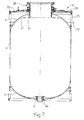
- Number 1 in Figures 1 and 2 indicates a cylindrical tank for solid propellant 2 for a rocket (not shown).
- Tank 1 has a longitudinal axis 3, and comprises a thermally protected casing 4 made of metal or composite material, and in turn comprising a cylindrical intermediate lateral wall 5 coaxial with axis 3, and two end covers 7 and 8.
- Cover 7 has a propellant ignition opening 9 coaxial with axis 3
- cover 8 has an opening 10, also coaxial with axis 3, for inserting the propellant, for housing a propulsion nozzle (not shown), and for inserting/withdrawing part of a fixture or tool 12 ( Figures 3 and 7-16), described in detail later on, for distributing propellant 2 as required inside tank 1.
- tool 12 provides for distributing the propellant so that propellant 2 defines an axial through cavity 13 comprising two end portions 14 and 15, each extending from a relative cover 7, 8, coaxially with relative opening 9, 10, and of which portion 15 comprises a number of dead channels 11 spaced angularly about axis 3.
- Cavity 13 also comprises an intermediate star-shaped portion 16 communicating with end portions 14 and 15 ( Figure 1).
- star-shaped portion 16 comprises a central space 17, and a number of lateral cavities or recesses 18 radiating and equally spaced angularly about axis 3.
- Each lateral recess 18 is bounded by flat radial surfaces 19 converging with each other towards cylindrical wall 5, and by a convex lateral surface 20 ( Figure 1).
- Lateral surface 20 is located at a distance D ( Figure 1), from axis 3, which increases towards cover 8, and, close to cover 8, reaches a maximum value greater than the radius R of opening 10 and comparable with the inside diameter of cylindrical wall 5.
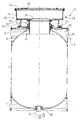
- cavity 13 is formed using tool 12, which comprises a locating and support assembly 22 connected integrally to metal casing 4 to surround cover 8 and opening 10; a rigid, contoured, strip-down plug 23 housable inside casing 4 through opening 10; and a positioning and retaining assembly 24 connectable to locating and support assembly 22 to lock plug 23 in the desired position inside casing 4 and permit pour-in of propellant 2 into the space left clear by strip-down plug 23.
- tool 12 comprises a locating and support assembly 22 connected integrally to metal casing 4 to surround cover 8 and opening 10; a rigid, contoured, strip-down plug 23 housable inside casing 4 through opening 10; and a positioning and retaining assembly 24 connectable to locating and support assembly 22 to lock plug 23 in the desired position inside casing 4 and permit pour-in of propellant 2 into the space left clear by strip-down plug 23.
- locating and support assembly 22 comprises a frame 25, which is fitted integrally to an outer surface of cover 8 and lateral wall 5, forms an axial extension of wall 5, and terminates with a connecting plate 26 perpendicular to axis 3.
- Positioning and retaining assembly 24 is fitted by screws 27 to plate 26, and comprises a box spacer body 28 screwed to plate 26; and a cup-shaped body 29 having a cylindrical lateral wall 31, and a bottom wall 30 welded to the free end of spacer body 28 and facing plate 26.
- Lateral wall 31 is fitted at its free end with a supporting plate 33 having an opening 34 coaxial with axis 3 and aligned with a further opening 35 formed through bottom wall 30 and also coaxial with axis 3.
- Opening 35 is surrounded by a telescopic collar 38 coaxial with axis 3 and comprising a first portion resting on plate 26, and a second portion connected to plate 26 and projecting inside casing 4 through opening 10 to form part of a known device 40, not described in detail, for tensioning a seal 41 isolating propellant 2.
- Seal 41 is housed partly inside casing 4, and partly extends to cover the inner surface of telescopic collar 38.
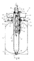
- Plate 33 supports and retains strip-down plug 23, which comprises a number of forming fins 43 (only one shown in Figure 3) selectable according to the desired geometry of cavity 13; and a cylindrical tubular locating body 44 coaxial with axis 3.
- Tubular body 44 comprises an end portion 45 connectable to a cap 46 closing opening 9; and an opposite end portion 47 projecting from plate 33 and defining a radial locator for fins 43.
- Each fin 43 is sized transversely to be insertable inside casing 4 through openings 34 and 35 and collar 38, and, in the example described, comprises a radial box forming portion 48 complementary in shape to that of lateral recesses 18, as shown in Figure 4; and an L-shaped stem 49 for connection to plate 33. More specifically, stem 49 comprises an axial portion 50 aligned with box portion 48; and a radial portion 51 having a number of through holes engaged loosely, in use, by respective screws 52 for connection to plate 33. As shown in Figure 3 and particularly in Figure 4, a peripheral axial portion of stem 49 forms part of an axial shank 53, in which is formed an axial groove 54 open, in use, towards axis 3 and having a substantially C-shaped cross section (Figure 4).
- Each groove 54 is sized to be engaged, in use, in axially sliding manner by the retaining heads 56 of a row of mushroom- or hammer- shaped bodies 57.
- Each body 57 comprises a radial stem 58, which engages in sliding manner a bush 58a inserted inside a radial opening 59 in tubular body 44, and projects inside tubular body 44.
- the portion of stem 58 extending inside tubular body 44 is fitted with a compression spring 60 forced between relative bush 58a and a stop nut 61 screwed to an end portion of stem 58 to keep head 56 in a withdrawn position ( Figures 3, 5, 6).
- each stem 58 is fitted with a known position detecting device 62 for detecting the position of head 56 in the slide direction A of stem 58.
- Bodies 57 in each row of bodies 57 are movable between said withdrawn position and an extracted position (shown by the dash line in Figures 5 and 6) by an actuating device 65 housed in tubular body 44.
- actuating device 65 is mechanical, and comprises a cap 66 fitted integrally and removably to the end of tubular body 44 extending through opening 34; and an elongated structure 66a extending axially inside body 44 and connected in known manner to cap 66.
- Structure 66a supports a guide, along which runs axially a slide 67 having a number of axially spaced cams 68.
- Each cam is associated with a respective cam-follower 69 ( Figures 3 and 5) which is hinged to structure 66a and rolls along respective cam 68 and against a free end of stem 58 of a respective mushroom-shaped body 57 to exert thrust, in use, in opposition to that of relative spring 60, and so push relative mushroom-shaped body 57 into the extracted position.
- a respective cam-follower 69 Figures 3 and 5 which is hinged to structure 66a and rolls along respective cam 68 and against a free end of stem 58 of a respective mushroom-shaped body 57 to exert thrust, in use, in opposition to that of relative spring 60, and so push relative mushroom-shaped body 57 into the extracted position.
- FIG. 6 and 11 variation shows an actuating device 70, which differs from device 65 solely by each cam and cam-follower assembly 68, 69 being replaced with a hydraulic linear actuator 71 located next to relative mushroom-shaped body 57, and having a movable member 72 ( Figure 6) coaxial with and acting directly on stem 58.
- spacer body 28, fitted integrally with cup-shaped body 29, is fitted to plate 26 and secured by screws 27; plate 33 for supporting fins 43 is then positioned on and connected to cup-shaped body 29, as shown in Figure 8; and fins 43 are then taken one by one and inserted successively inside casing 4 through openings 34 and 35 and telescopic collar 38 (Figure 9).
- Each fin 43 is first inserted axially, is then moved radially to rest portion 51 of stem 49 on plate 33, and is then set to a predetermined angular position and fastened to plate 33 by screws 52, which engage respective through holes in portion 51 with a certain amount of radial clearance to permit fine radial adjustment of fin 43 later ( Figure 9). Screws 52 are also tightened to permit a small amount of axial movement of fins 43 with respect to plate 33, i.e. to also leave a certain axial clearance enabling fine axial adjustment later on, as described in detail below.
- fins 43 are all inserted inside casing 4 and fastened to plate 33, they are maintained in this rough position, and actuating device 65 or 70 (Figure 10 or 11) is inserted inside tubular body 44 so that cap 66 engages the end of portion 47, at which point, cap 66 is fastened by screws 75.
- cam-followers 69 when using mechanical device 65 ( Figure 10), or actuators 71, when using hydraulic device 70 ( Figure 11), are each aligned with the free end of stem 58 of a respective mushroom-shaped body 57.
- actuating device 65, 70 is operated to move mushroom-shaped bodies 57 into the extracted position shown by the dash line in Figures 5 and 6; portion 45 of tubular body 44 is then inserted inside casing 4, through openings 34 and 35 and collar 38, and is positioned coaxially with axis 3; tubular body 44 is then rotated about axis 3 to align each row of mushroom-shaped bodies 57 with groove 54 of a respective fin 43, and is moved axially to ease head 56 of each mushroom-shaped body 57 inside relative groove 54, and so that portion 45 engages and rests on cap 46, as shown in Figure 3. During insertion, as described above, any angular position errors of fins 43 are corrected.
- actuating device 65, 70 is deactivated, and mushroom-shaped bodies 57 are moved by relative springs 60 into the withdrawn position, in which heads 56 first come to rest on the shoulders 76 of groove 54, as shown in Figures 4, 5 and 6, and then move fins 43 radially (this is permitted by the radial clearance of screws 52 inside the respective holes) towards tubular body 44, and hold them firmly against the outer surface of tubular body 44.
- cap 66 coaxial with axis 3, is fitted with a body 77 for axially positioning and retaining fins 43, as shown in Figure 12.
- Body 77 is star-shaped, and comprises, for each fin 43, a respective arm 78 projecting from tubular body 44 and over respective portion 51.
- Each arm 78 is then fastened to relative portion 51 by partly tightening axial screws 79; screws 52 and plate 33 are then removed, and the corresponding actuating device 65, 70 is again activated to ease mushroom-bodies 57 back into the extracted position; and screws 79 are then tightened to move fins 43 axially so that portions 51 rest against corresponding arms 78.
- bodies 57 provide simply for guidance.
- actuating device 65, 70 is again deactivated, and fins 43 are again forced against the outer surface of tubular body 44 by mushroom-shaped bodies 57. Fins 43 are therefore connected integrally to tubular body 44 alone, and are each set to a predetermined axial and angular work position (Figure 12).
- cup-shaped body 29 from where it is allowed to flow into casing 4 along a number of axial channels 86 - only one shown in Figures 13 and 14 - bounded laterally by adjacent fins 43.
- the propellant is fed in to completely fill tank 1 and channels 86, and part of cup-shaped body 29, as shown in Figure 14.
- centring device 84 is removed and replaced with a forming device 87 ( Figure 15) comprising a fastening collar 88 fitted to cap 66 by screws 89a; and, for each channel 86, a hollow, elongated, circular partition 89 connected integrally to collar 88 and terminating, at the opposite end to collar 88, with a pointed portion 90 having a number of adjacent axial through holes 91.
- Forming device 87 is moved axially to insert pointed portions 90 inside the propellant inside cup-shaped shaped body 29, and to slide each partition 89 axially inside the relative channel 86.
- the propellant flows through holes 91 to gradually fill the gap K between each partition 89 and tubular body 44, and to enclose a ribbed rod 93 housed inside gap K and connected integrally to collar 88.
- centring device 84 is replaced, and the propellant heat treated in known manner. After heat treatment, centring device 84 is removed, and forming device 87 extracted.
- forming device 87 the portions of propellant between partitions 89 and tubular body 44 and anchored to relative ribbed rods 93 are inevitably also extracted, thus clearing channels 86, as shown in Figure 16, so that each channel 86 forms a relative dead channel 11 of cavity 13.
- Centring device 84 and retaining body 79a are then removed, cap 66 is replaced and actuating device 65, 70 reinserted, plate 33 for supporting fins 43 is replaced, and fins 43 are fitted back onto plate 33 by means of screws 52, as shown in Figure 16.
- actuating device 65 is activated to move mushroom-shaped bodies 57 into the extracted position, and tubular body 44 is then withdrawn to clear a through channel along which fins 43 are withdrawn successively, keeping them parallel to themselves, before being extracted axially through collar 38 to clear cavity 13.
- Tool 12 described therefore provides for forming, in the propellant in tank 1, any type of cavity, even having underside recesses, and in particular a cavity of radial dimensions greater than the radial dimension of the opening through which the propellant is fed.
- a rigid, strip-down plug the rigid component parts of which may, above all, be selected from a number of rigid parts of any shape and size, can be inserted successively inside the casing, and, once inside the casing, can be set and locked releasably in predetermined fixed positions.
- cavities of any shape and size are obtained simply and relatively cheaply, by virtue of the plugs and the tool 12 described comprising a small number of component parts that are easy to make and assemble, and by virtue of the tool itself and the plug fastening member being universal, i.e. usable with any type of forming fin, and therefore for forming any type of cavity.
- plug 23 may differ from the one described by way of example, while still comprising rigid component parts than can be assembled and disassembled inside the tank working from the outside.
Landscapes
- Engineering & Computer Science (AREA)
- Chemical & Material Sciences (AREA)
- Combustion & Propulsion (AREA)
- Mechanical Engineering (AREA)
- General Engineering & Computer Science (AREA)
- Shaping Metal By Deep-Drawing, Or The Like (AREA)
- Portable Nailing Machines And Staplers (AREA)
Applications Claiming Priority (2)
| Application Number | Priority Date | Filing Date | Title |
|---|---|---|---|
| ITTO20030799 ITTO20030799A1 (it) | 2003-10-10 | 2003-10-10 | Metodo per la distibuzione di un propellente all'interno |
| ITTO20030799 | 2003-10-10 |
Publications (2)
| Publication Number | Publication Date |
|---|---|
| EP1522711A2 true EP1522711A2 (fr) | 2005-04-13 |
| EP1522711A3 EP1522711A3 (fr) | 2005-06-08 |
Family
ID=34308168
Family Applications (1)
| Application Number | Title | Priority Date | Filing Date |
|---|---|---|---|
| EP04104956A Withdrawn EP1522711A3 (fr) | 2003-10-10 | 2004-10-08 | Procédure de distribution du propergol dans un boítier de propergol solide et outil à la mise en oeuvre de la procédure |
Country Status (2)
| Country | Link |
|---|---|
| EP (1) | EP1522711A3 (fr) |
| IT (1) | ITTO20030799A1 (fr) |
Cited By (4)
| Publication number | Priority date | Publication date | Assignee | Title |
|---|---|---|---|---|
| FR3035661A1 (fr) * | 2015-04-30 | 2016-11-04 | Herakles | Ensemble pour l'extraction d'au moins un secteur de moule |
| JP2018514681A (ja) * | 2015-03-27 | 2018-06-07 | チェアマン, ディフェンス リサーチ アンド ディヴェロップメント オーガナイゼーション (ディーアールディーオー)Chairman, Defence Research & Development Organisation (Drdo) | マンドレル組立体、及びこのマンドレル組立体を用いて固体ロケットの推進薬グレインを製造する方法 |
| CN110230553A (zh) * | 2019-07-15 | 2019-09-13 | 武汉乾峯智能科技有限公司 | 自动化取模装置 |
| FR3090751A1 (fr) * | 2018-12-20 | 2020-06-26 | Arianegroup Sas | Noyau démontable pour la fabrication d'un chargement de propergol et procédé de mise en oeuvre |
Citations (6)
| Publication number | Priority date | Publication date | Assignee | Title |
|---|---|---|---|---|
| US3270999A (en) * | 1963-04-12 | 1966-09-06 | Thiokol Chemical Corp | Segmented core for molding a cavity in a cast solid propellant rocket motor |
| US3345438A (en) * | 1966-02-25 | 1967-10-03 | Donald F Carey | Mandrel casting solid propellant rocket fuel |
| US3345693A (en) * | 1965-01-27 | 1967-10-10 | Thiokol Chemical Corp | Apparatus for forming ignition surfaces in solid propellant motors |
| US3567174A (en) * | 1968-03-18 | 1971-03-02 | Thiokol Chemical Corp | Breakdown core for forming a cavity in a solid propellant grain |
| US4000682A (en) * | 1960-09-07 | 1977-01-04 | The United States Of America As Represented By The Administrator Of The National Aeronautics And Space Administration | Solid propellant rocket motor and method of making same |
| US5714081A (en) * | 1995-08-04 | 1998-02-03 | Societe Nationale Des Poudres Et Explosifs | Dismountable mechanical core and procedure for implementing it |
-
2003
- 2003-10-10 IT ITTO20030799 patent/ITTO20030799A1/it unknown
-
2004
- 2004-10-08 EP EP04104956A patent/EP1522711A3/fr not_active Withdrawn
Patent Citations (6)
| Publication number | Priority date | Publication date | Assignee | Title |
|---|---|---|---|---|
| US4000682A (en) * | 1960-09-07 | 1977-01-04 | The United States Of America As Represented By The Administrator Of The National Aeronautics And Space Administration | Solid propellant rocket motor and method of making same |
| US3270999A (en) * | 1963-04-12 | 1966-09-06 | Thiokol Chemical Corp | Segmented core for molding a cavity in a cast solid propellant rocket motor |
| US3345693A (en) * | 1965-01-27 | 1967-10-10 | Thiokol Chemical Corp | Apparatus for forming ignition surfaces in solid propellant motors |
| US3345438A (en) * | 1966-02-25 | 1967-10-03 | Donald F Carey | Mandrel casting solid propellant rocket fuel |
| US3567174A (en) * | 1968-03-18 | 1971-03-02 | Thiokol Chemical Corp | Breakdown core for forming a cavity in a solid propellant grain |
| US5714081A (en) * | 1995-08-04 | 1998-02-03 | Societe Nationale Des Poudres Et Explosifs | Dismountable mechanical core and procedure for implementing it |
Cited By (6)
| Publication number | Priority date | Publication date | Assignee | Title |
|---|---|---|---|---|
| JP2018514681A (ja) * | 2015-03-27 | 2018-06-07 | チェアマン, ディフェンス リサーチ アンド ディヴェロップメント オーガナイゼーション (ディーアールディーオー)Chairman, Defence Research & Development Organisation (Drdo) | マンドレル組立体、及びこのマンドレル組立体を用いて固体ロケットの推進薬グレインを製造する方法 |
| EP3274579A4 (fr) * | 2015-03-27 | 2018-11-14 | Chairman, Defence Research & Development Organisation (DRDO) | Ensemble mandrin et procédé de fabrication de grains de propergol solide le mettant en uvre |
| US10634093B2 (en) * | 2015-03-27 | 2020-04-28 | Chairman, Defence Research & Development Organisation | Mandrel assembly and method of manufacturing solid rocket propellant grain using the same |
| FR3035661A1 (fr) * | 2015-04-30 | 2016-11-04 | Herakles | Ensemble pour l'extraction d'au moins un secteur de moule |
| FR3090751A1 (fr) * | 2018-12-20 | 2020-06-26 | Arianegroup Sas | Noyau démontable pour la fabrication d'un chargement de propergol et procédé de mise en oeuvre |
| CN110230553A (zh) * | 2019-07-15 | 2019-09-13 | 武汉乾峯智能科技有限公司 | 自动化取模装置 |
Also Published As
| Publication number | Publication date |
|---|---|
| ITTO20030799A1 (it) | 2005-04-11 |
| EP1522711A3 (fr) | 2005-06-08 |
Similar Documents
| Publication | Publication Date | Title |
|---|---|---|
| EP3003681B1 (fr) | Dispositif de reglage de position de tige de soupape | |
| US7886760B2 (en) | Electromagnetic adjustment unit | |
| US5699947A (en) | Process and machine for parting the cap of connecting rods, particularly connecting rods for internal-combustion engines | |
| US10260535B2 (en) | Multi-purpose and tunable pressure chamber for pyrotechnic actuator | |
| JPH0543889B2 (fr) | ||
| EP2777868B1 (fr) | Dispositif de positionnement d'au moins un élément fonctionnel et procédé d'assemblage thermique d'un arbre avec des éléments fonctionnels ayant chacun un moyeu pour l'arbre | |
| JP2013036399A (ja) | 直噴式エンジン用フューエルレールアッシーの組付方法 | |
| DE3739803A1 (de) | Spritzgussvorrichtung | |
| EP1522711A2 (fr) | Procédure de distribution du propergol dans un boítier de propergol solide et outil à la mise en oeuvre de la procédure | |
| US20140245582A1 (en) | Apparatus for Assembling Camshaft | |
| DE102018109751A1 (de) | Aktuator für einen Schwenkmotorversteller und Schwenkmotorversteller für eine Nockenwelle | |
| US9879576B2 (en) | Adjustable camshaft | |
| US20080236436A1 (en) | Pyrotechnic drive unit and method for the production of such a unit | |
| US8562889B2 (en) | Method for producing plastic cylinder head cover | |
| US20070181086A1 (en) | Assembled camshaft with camshaft setting device | |
| KR20030094397A (ko) | 링 형 공작물의 기계 가공 방법 및 장치 | |
| US4827585A (en) | Cam shaft manufacturing method and device used therein | |
| JP6027882B2 (ja) | バルブコッター嵌込システム及びバルブコッター嵌込方法 | |
| JPH072084A (ja) | 油圧マスタシリンダ | |
| US6442987B1 (en) | Method of producing a shaft from a piece of tubing, apparatus for making a shaft from a piece of tubing and camshaft produced from a piece of tubing | |
| US11312051B2 (en) | Stem connector for melt-distribution assembly of molding system | |
| US8071005B2 (en) | Method and plant for the production of a casing for a solid-propellant engine | |
| EP4350168A1 (fr) | Amortisseur et procédé de fabrication d'amortisseur | |
| EP3009660B1 (fr) | Ensemble de soupape pourvu d'un élément de guidage et injecteur de fluide | |
| US20240076007A1 (en) | Adjustable height or dropper seatpost for bicycle |
Legal Events
| Date | Code | Title | Description |
|---|---|---|---|
| PUAI | Public reference made under article 153(3) epc to a published international application that has entered the european phase |
Free format text: ORIGINAL CODE: 0009012 |
|
| AK | Designated contracting states |
Kind code of ref document: A2 Designated state(s): AT BE BG CH CY CZ DE DK EE ES FI FR GB GR HU IE IT LI LU MC NL PL PT RO SE SI SK TR |
|
| AX | Request for extension of the european patent |
Extension state: AL HR LT LV MK |
|
| PUAL | Search report despatched |
Free format text: ORIGINAL CODE: 0009013 |
|
| AK | Designated contracting states |
Kind code of ref document: A3 Designated state(s): AT BE BG CH CY CZ DE DK EE ES FI FR GB GR HU IE IT LI LU MC NL PL PT RO SE SI SK TR |
|
| AX | Request for extension of the european patent |
Extension state: AL HR LT LV MK |
|
| 17P | Request for examination filed |
Effective date: 20051206 |
|
| RIN1 | Information on inventor provided before grant (corrected) |
Inventor name: VINCENZI, VINCENZO Inventor name: ZARRA, GERARDO Inventor name: SPINOSA, SALVATORE Inventor name: SESSA, DARIO Inventor name: MILIENI, ANTONELLA |
|
| AKX | Designation fees paid |
Designated state(s): DE FR GB IT |
|
| STAA | Information on the status of an ep patent application or granted ep patent |
Free format text: STATUS: THE APPLICATION IS DEEMED TO BE WITHDRAWN |
|
| 18D | Application deemed to be withdrawn |
Effective date: 20060919 |