EP1522604A1 - Layer system and process for its production - Google Patents
Layer system and process for its production Download PDFInfo
- Publication number
- EP1522604A1 EP1522604A1 EP03022540A EP03022540A EP1522604A1 EP 1522604 A1 EP1522604 A1 EP 1522604A1 EP 03022540 A EP03022540 A EP 03022540A EP 03022540 A EP03022540 A EP 03022540A EP 1522604 A1 EP1522604 A1 EP 1522604A1
- Authority
- EP
- European Patent Office
- Prior art keywords
- layer
- anchoring means
- substrate
- layer system
- intermediate layer
- Prior art date
- Legal status (The legal status is an assumption and is not a legal conclusion. Google has not performed a legal analysis and makes no representation as to the accuracy of the status listed.)
- Granted
Links
- 238000000034 method Methods 0.000 title claims description 23
- 238000004519 manufacturing process Methods 0.000 title claims description 7
- 238000004873 anchoring Methods 0.000 claims abstract description 62
- 239000000758 substrate Substances 0.000 claims abstract description 50
- 239000000463 material Substances 0.000 claims description 20
- 238000002485 combustion reaction Methods 0.000 claims description 15
- 230000004927 fusion Effects 0.000 claims description 4
- 238000003466 welding Methods 0.000 claims description 3
- 238000005272 metallurgy Methods 0.000 claims 1
- 238000000576 coating method Methods 0.000 abstract description 11
- 239000011248 coating agent Substances 0.000 abstract description 5
- 239000010410 layer Substances 0.000 description 105
- 239000007789 gas Substances 0.000 description 12
- 239000000919 ceramic Substances 0.000 description 8
- 239000012720 thermal barrier coating Substances 0.000 description 5
- 239000000203 mixture Substances 0.000 description 3
- 238000005266 casting Methods 0.000 description 2
- 230000007797 corrosion Effects 0.000 description 2
- 238000005260 corrosion Methods 0.000 description 2
- 238000009792 diffusion process Methods 0.000 description 2
- 238000010438 heat treatment Methods 0.000 description 2
- 238000004372 laser cladding Methods 0.000 description 2
- 239000000843 powder Substances 0.000 description 2
- 239000011241 protective layer Substances 0.000 description 2
- 230000003746 surface roughness Effects 0.000 description 2
- YPFNIPKMNMDDDB-UHFFFAOYSA-K 2-[2-[bis(carboxylatomethyl)amino]ethyl-(2-hydroxyethyl)amino]acetate;iron(3+) Chemical compound [Fe+3].OCCN(CC([O-])=O)CCN(CC([O-])=O)CC([O-])=O YPFNIPKMNMDDDB-UHFFFAOYSA-K 0.000 description 1
- 239000011449 brick Substances 0.000 description 1
- 229910010293 ceramic material Inorganic materials 0.000 description 1
- 229910017052 cobalt Inorganic materials 0.000 description 1
- 239000010941 cobalt Substances 0.000 description 1
- GUTLYIVDDKVIGB-UHFFFAOYSA-N cobalt atom Chemical compound [Co] GUTLYIVDDKVIGB-UHFFFAOYSA-N 0.000 description 1
- 239000002826 coolant Substances 0.000 description 1
- 238000001816 cooling Methods 0.000 description 1
- 230000001419 dependent effect Effects 0.000 description 1
- 239000000446 fuel Substances 0.000 description 1
- 238000002347 injection Methods 0.000 description 1
- 239000007924 injection Substances 0.000 description 1
- 238000009413 insulation Methods 0.000 description 1
- 239000000155 melt Substances 0.000 description 1
- 230000006911 nucleation Effects 0.000 description 1
- 238000010899 nucleation Methods 0.000 description 1
- 238000007750 plasma spraying Methods 0.000 description 1
- 239000011253 protective coating Substances 0.000 description 1
- 238000009419 refurbishment Methods 0.000 description 1
- 238000004901 spalling Methods 0.000 description 1
- 230000035882 stress Effects 0.000 description 1
- 229910000601 superalloy Inorganic materials 0.000 description 1
- 230000008646 thermal stress Effects 0.000 description 1
Images

Classifications
-
- C—CHEMISTRY; METALLURGY
- C23—COATING METALLIC MATERIAL; COATING MATERIAL WITH METALLIC MATERIAL; CHEMICAL SURFACE TREATMENT; DIFFUSION TREATMENT OF METALLIC MATERIAL; COATING BY VACUUM EVAPORATION, BY SPUTTERING, BY ION IMPLANTATION OR BY CHEMICAL VAPOUR DEPOSITION, IN GENERAL; INHIBITING CORROSION OF METALLIC MATERIAL OR INCRUSTATION IN GENERAL
- C23C—COATING METALLIC MATERIAL; COATING MATERIAL WITH METALLIC MATERIAL; SURFACE TREATMENT OF METALLIC MATERIAL BY DIFFUSION INTO THE SURFACE, BY CHEMICAL CONVERSION OR SUBSTITUTION; COATING BY VACUUM EVAPORATION, BY SPUTTERING, BY ION IMPLANTATION OR BY CHEMICAL VAPOUR DEPOSITION, IN GENERAL
- C23C4/00—Coating by spraying the coating material in the molten state, e.g. by flame, plasma or electric discharge
- C23C4/18—After-treatment
-
- C—CHEMISTRY; METALLURGY
- C23—COATING METALLIC MATERIAL; COATING MATERIAL WITH METALLIC MATERIAL; CHEMICAL SURFACE TREATMENT; DIFFUSION TREATMENT OF METALLIC MATERIAL; COATING BY VACUUM EVAPORATION, BY SPUTTERING, BY ION IMPLANTATION OR BY CHEMICAL VAPOUR DEPOSITION, IN GENERAL; INHIBITING CORROSION OF METALLIC MATERIAL OR INCRUSTATION IN GENERAL
- C23C—COATING METALLIC MATERIAL; COATING MATERIAL WITH METALLIC MATERIAL; SURFACE TREATMENT OF METALLIC MATERIAL BY DIFFUSION INTO THE SURFACE, BY CHEMICAL CONVERSION OR SUBSTITUTION; COATING BY VACUUM EVAPORATION, BY SPUTTERING, BY ION IMPLANTATION OR BY CHEMICAL VAPOUR DEPOSITION, IN GENERAL
- C23C4/00—Coating by spraying the coating material in the molten state, e.g. by flame, plasma or electric discharge
- C23C4/02—Pretreatment of the material to be coated, e.g. for coating on selected surface areas
-
- Y—GENERAL TAGGING OF NEW TECHNOLOGICAL DEVELOPMENTS; GENERAL TAGGING OF CROSS-SECTIONAL TECHNOLOGIES SPANNING OVER SEVERAL SECTIONS OF THE IPC; TECHNICAL SUBJECTS COVERED BY FORMER USPC CROSS-REFERENCE ART COLLECTIONS [XRACs] AND DIGESTS
- Y02—TECHNOLOGIES OR APPLICATIONS FOR MITIGATION OR ADAPTATION AGAINST CLIMATE CHANGE
- Y02T—CLIMATE CHANGE MITIGATION TECHNOLOGIES RELATED TO TRANSPORTATION
- Y02T50/00—Aeronautics or air transport
- Y02T50/60—Efficient propulsion technologies, e.g. for aircraft
Definitions
- the invention relates to a layer system according to the preamble of claim 1 and method for producing a Layer system according to the preamble of claims 18 and 19.
- Components for high temperatures are usually provided with protective coatings today. These may be metallic anticorrosion coatings (MCrAlX coatings) or ceramic thermal barrier coatings as well as coating systems with metallic anticorrosion coatings and ceramic thermal barrier coatings.
- MrAlX coatings metallic anticorrosion coatings
- ceramic thermal barrier coatings as well as coating systems with metallic anticorrosion coatings and ceramic thermal barrier coatings.
- As a coating method for these coatings used plasma-assisted powder injection process due to their comparatively high efficiency. The bonding of such layers to the substrate takes place by mechanical clamping and subsequent diffusion heat treatment. Occasionally, in highly stressed areas or at unfavorable, ie particularly at high mechanical stress points of the component to a detachment of the layer come in operation. The spalling of the layer during operation leads to damage to the base material, so that the component life is significantly reduced.
- the object is achieved by a layer system according to the claim 1 or by a method for producing a Layer system according to claims 18 and 19.
- the layer system according to the invention has separately produced Anchoring means on which a very strong connection to the Substrate or to a below it arranged on the substrate Have layer and in other ways than the Layer bonded to the substrate or the other layer are.
- the anchoring means is done for example by a fusion metallurgical bond, which in a separate process is produced.
- the cost-effective and economical plasma spraying can be used to to apply the layer.
- FIG. 1 shows a layer system according to the prior art.
- the layer system has a substrate 4.
- the substrate 4 may be metallic or ceramic and is in the case of gas turbine components, in particular made of an iron-, nickel- or cobalt-based superalloy.
- At least one layer 7, 9 (in FIG. 6, 7, 8 two layers) available. This can be a metallic one and / or ceramic layer 7, 9 be.
- a metallic corrosion protection layer. 7 (Fig. 6, 7, 8) of the type MCrAlX applied, whereupon in addition another external, for example, a ceramic Thermal insulation layer 9 (Fig. 6, 7, 8) is applied.
- connection of the intermediate layer 7 on the substrate 4 or the layers 7, 9 with each other takes place according to the previous State of the art solely by mechanical clamping (Surface roughness) to the underlying surface and subsequent Diffusion heat treatment.
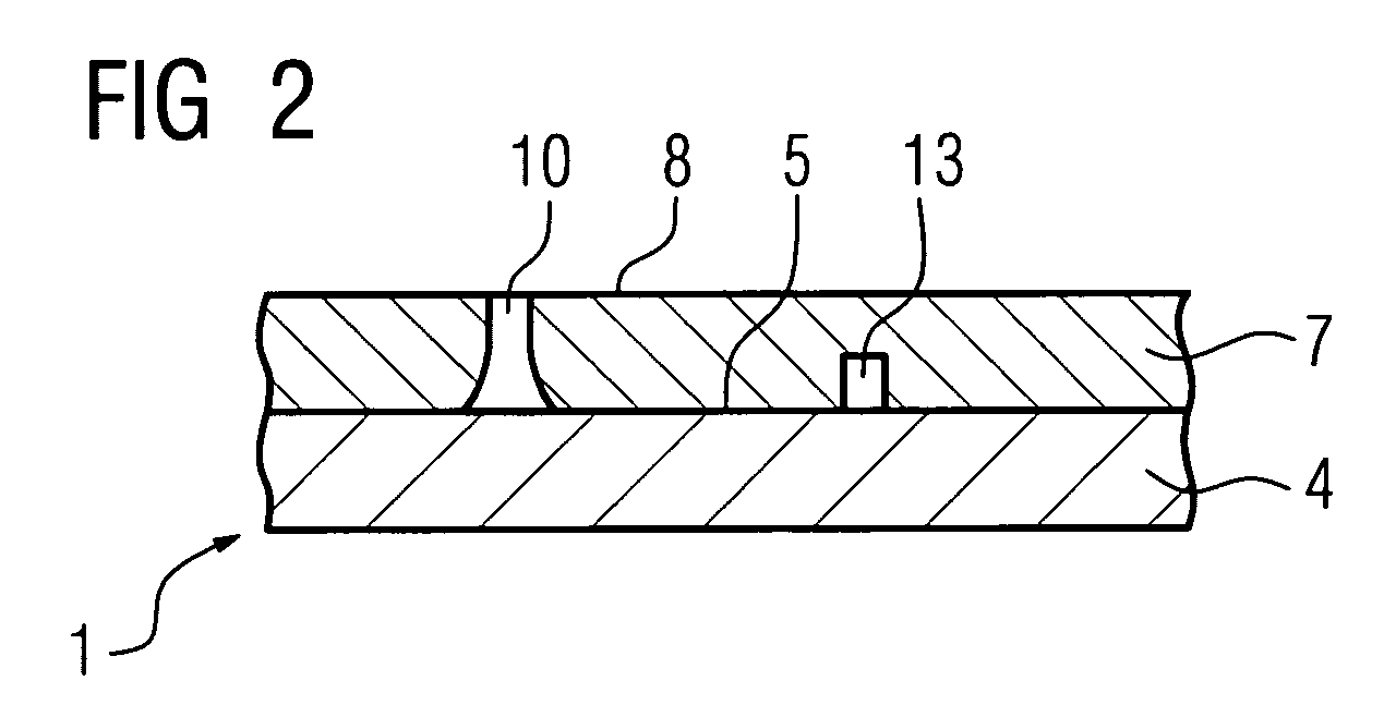
- FIG. 2 shows, starting from FIG. 1, a layer system 1 according to the invention.
- Anchoring means 10, 13 are provided on the surface 5 of the substrate 4.
- the anchoring means 10, 13 have a type of connection to the surface 5, which results in an increased bonding force (more precisely: force / per contact surface) to the surface 5 compared to the type of connection of the intermediate layer 7 to the surface 5.
- the anchoring means 10, 13 are bonded to the substrate 4, for example, by a suitably guided laser welding process. It is likewise conceivable that the layer 7 is applied at specific points by laser cladding (laser powder coating) and thus forms anchoring means 10, 13.
- the anchoring means 10, 13 can also be cast or produced during casting of the substrate 4 with.
- the anchoring means 10, 13 provide adhesion bridges for the layer 7, 9 surrounding the anchoring means 10, 13.
- the anchoring means 10 may extend from the surface 5 of the substrate 4 to the outer surface 8 of the intermediate layer 7 or they 13 are covered by the layer 7, so that the anchoring means 13 do not extend to the surface 8 of the layer 7, ie are disposed within the layer 7, 9 ending. They extend 13 to at least 10%, 20%, 30%, 40% of the thickness of the layer 7, 9 in the layer 7, 9th
- the anchoring means 10, 13 are for example only locally, so localized ( Figure 3) on the substrate 4 or the layer 7 is present, namely where the mechanical load is greatest. This is, for example, the area of the leading edge of a turbine blade 120, 130. The remaining blade would then have no anchoring means.
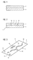
- FIG. 3 shows a plan view of a surface 8 of a layer 7. Dashed lines indicate the anchoring means 13, which do not extend to the surface 8 of the layer 7.
- the anchoring means 10, 13 may have on the surface 5 different geometries such as circles, stitching (ie they are elongated and intersecting), waveforms, parallel paths and combinations thereof.
- FIG. 6 shows a further layer system 1 designed according to the invention.
- the layer system 1 consists of a substrate 4 and two layers 7, 9.
- the intermediate layer 7 is, for example, a metallic one MCrAlX layer and the outer layer 9 is for example a ceramic thermal barrier coating 9 on the intermediate layer. 7
- Anchoring means 10, 13 are both in the intermediate layer 7 as well as in the outer layer 9 available.
- the intermediate layer 7 need not have anchoring means 10, 13 in the sense of the present invention (FIG. 8). Likewise, the anchoring means only in the intermediate layer 7 be present (Fig. 7).
- the anchoring means 10, 13 in the layers 7, 9 can starting from the surface 5, 8 of the substrate 4 or the intermediate layer 7 to the outer surface 8, 16 of the Layer 7, 9 extend through the layers 7, 9 covered, so that the anchoring means 13 is not up to the surface 8, 16 of the layers 7, 9 extend.
- the anchoring means 10, 13 in the intermediate layer 7 improve the bonding of the intermediate layer 7 to the substrate 4.
- the material of the anchoring means 10 of the layer 7 can, for example, also be chosen such that improved adhesion of the outer layer 9 to the anchoring means 10 results (FIG. 7).
- the material of the anchoring means 10 in the intermediate layer 7 may be ceramic, whereby the ceramic thermal barrier coating 9 can better connect with the anchoring means 10 which extend up to the surface 8 of the intermediate layer 7 or the anchoring means 10 serve as growth nuclei, in particular during epitaxial growth, during coating of the intermediate layer 7 with the ceramic material of the outer layer 9.
- the material composition of anchoring means 10, 13 in the layers 7, 9 is chosen appropriately depending on the requirement.
- the anchoring means 10, 13 are in particular in thermal and / or mechanically highly loaded areas present.
- the layer system 1 is, for example, a component of a gas 100 (Fig. 9) (also aircraft turbine) or steam turbine. thermal highly loaded components of the turbines have such Layer system, such as Turbine blades 120, 130, linings 155 a combustion chamber 110 and other housing parts, along the flow path of a hot vapor or hot gases are located.
- the layer system 1 can be applied to a newly manufactured component be applied as well as on components after use to be worked up again (refurbishment).
- FIG. 7 shows a further exemplary embodiment of a layer system 1 according to the invention.
- the anchoring means 10, 13 are present only in the intermediate layer 7.
- the outer layer 9 is present.
- a contact surface of the anchoring means 10 on the surface 8 improves the adhesion of the outer layer 9 to a comparable contact surface with the intermediate layer 7. This is achieved, for example, in that the contact surfaces of the anchoring means 10 on the surface 8 nucleation points for example, epitaxial growth of an outer Layer 9 on the intermediate layer 7.
- an improved layer system 1 is achieved in that the anchoring means 10, 13 lead to an improved connection of the outer layer 9 to the substrate 4.
- FIG. 8 shows a further exemplary embodiment of a layer system 1 according to the invention.
- the anchoring means 10, 13 are present only in the outer layer 9, ie they are present on the intermediate layer 7, which lead to a better connection of the outer layer 9 to the underlying intermediate layer 7.
- the anchoring means 10, 13 are then bonded to the surface 8 of the intermediate layer 7.
- FIG. 4 shows exemplary method steps of a method according to the invention for producing a layer system 1.
- the at least one layer 7, 9 is applied to the substrate 4 or to a layer already on the substrate in a known manner.
- the layer 7, 9 is with a laser 16 or an electron gun 16 deals with a corresponding laser or E-beam 19 emits.
- This kind of treatment becomes the material of the layer 7, 9 to the surface 5, 8 of the substrate 4 and the intermediate layer 7 out locally converted, for example, melted, leaving a Melt metallurgical bonding of material from the layer 7, 9 to the substrate 4 or already applied thereto Layer results.
- This method becomes anchoring means 10, which extends from the surface 5, 8 to the Surface 8, 16 of the layer 7, 9 extend.
- the anchoring means 10 are, for example, columnar trained and can also run concave or convex curved be (Fig. 7).
- FIG. 5 shows another example of the invention Method.
- the anchoring means 10, 13 are first applied to the substrate 4 or the layer 7, that is to say produced separately. This can be done in various ways, such as by a suitably guided laser welding process or Lasercladding.
- the anchoring means 10, 13 have a very strong, in particular fusion metallurgical connection to the surface 5, 8 of the substrate 4 or the intermediate layer 7.
- the anchoring means 10, 13 but also already at the production of the substrate 4, for example through a casting process.
- the layer 7, 9 is applied, wherein the anchoring means 10, 13 of the material the layer 7, 9 are enclosed and liability bridges for the layer 7, 9 represent.
- the material of the anchoring means 10, 13 may be equal to Material of the layer 7, 9, equal to the material of the substrate 4 or equal to the material of a subsequent layer or also have a different material composition.
- the material the anchoring means 10, 13 in the layer 7 must not necessarily equal to the material of the substrate 4.
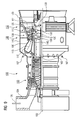
- FIG. 9 shows a gas turbine 100 in a longitudinal partial section.
- the gas turbine 100 has inside a rotatably mounted about a rotation axis 102 rotor 103, which is also referred to as a turbine runner.
- a compressor 105 for example a toroidal combustion chamber 110, in particular annular combustion chamber 106, with a plurality of coaxially arranged burners 107, a turbine 108 and the exhaust housing 109.
- the annular combustion chamber 106 communicates with an annular annular hot gas channel 111, for example.
- There, for example, four successive turbine stages 112 form the turbine 108.
- Each turbine stage 112 is formed from two blade rings.
- a series 125 formed of rotor blades 120 follows.
- the vanes 130 are attached to the stator 143, whereas the blades 120 of a series 125 by means of a Turbine disk 133 are mounted on the rotor 103.
- To the Rotor 103 is coupled to a generator or a work machine (not shown).
- the gas turbine 100 During operation of the gas turbine 100 is from the compressor 105 sucked and compressed by the intake 104 104 air 135.
- the provided at the turbine end of the compressor 105 compressed air is fed to the burners 107 and mixed there with a fuel.
- the mixture is then to form the working medium 113 in the combustion chamber 110 burned. From there, the working medium flows 113 along the hot gas channel 111 past the vanes 130 and the blades 120. Relaxed on the blades 120 the working medium 113 is pulse-transmitting, so that the blades 120 drive the rotor 103 and this the attached to him work machine.
- the components exposed to the hot working medium 113 are subject to thermal loads during operation of the gas turbine 100.
- the guide vanes 130 and rotor blades 120 of the first turbine stage 112, viewed in the direction of flow of the working medium 113, are subjected to the greatest thermal stress in addition to the heat shield bricks lining the annular combustion chamber 106. In order to withstand the temperatures prevailing there, they are cooled by means of a coolant.
- the vane 130 has an inner housing 138 of the Turbine 108 facing Leitschaufelfuß (not shown here) and a vane foot opposite Guide vane head on.
- the vane head is the rotor 103 facing and on a mounting ring 140 of the stator 143rd established.
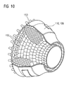
- FIG. 10 shows a combustion chamber 110 of a gas turbine 100.
- the combustion chamber 110 is, for example, a so-called annular combustion chamber designed, in which a variety of circumferentially arranged around the turbine shaft 103 around Burners 102 open into a common combustion chamber space.
- the combustion chamber 110 in its entirety as an annular Structure designed around the turbine shaft 103rd is positioned around.
- the working medium M of about 1000 ° C to 1600 ° C designed.
- the combustion chamber wall 153 on its the working medium M facing side with one of heat shield elements 155 formed inner lining provided.
- Each heat shield element 155 is working medium side with a particularly heat-resistant Protective layer equipped or made of high temperature resistant Material made. Due to the high temperatures inside the combustion chamber 110 is also for the Heat shield elements 155 or for their holding elements Cooling system provided.
Landscapes
- Chemical & Material Sciences (AREA)
- Engineering & Computer Science (AREA)
- Physics & Mathematics (AREA)
- Plasma & Fusion (AREA)
- Chemical Kinetics & Catalysis (AREA)
- Materials Engineering (AREA)
- Mechanical Engineering (AREA)
- Metallurgy (AREA)
- Organic Chemistry (AREA)
- Turbine Rotor Nozzle Sealing (AREA)
- Other Surface Treatments For Metallic Materials (AREA)
Abstract
Schichtsysteme nach dem Stand der Technik weisen oft aufgrund ihrer Beschichtungsart nur eine geringe Anbindung an das Substrat auf. Bei mechanisch hochbelasteten Bauteilen kann es dann zu einer Ablösung der Schicht kommen.Layer systems of the prior art are often due to Their coating only a small connection to the substrate on. For mechanically highly stressed components it can then come to a replacement of the layer.
Das erfindungsgemäße Schichtsystem (1) weist gesondert erzeugte
Verankerungsmittel (10, 13) auf, die eine stärkere Anbindung
an das Substrat (4) als die Schicht (7) and das Substrat
(4) aufweisen.
Description
Die Erfindung betrifft ein Schichtsystem gemäß dem Oberbegriff
des Anspruchs 1 und Verfahren zur Herstellung eines
Schichtsystems gemäß dem Oberbegriff der Ansprüche 18 und 19.The invention relates to a layer system according to the preamble
of
Bauteile für hohe Temperaturen werden heutzutage in der Regel
mit Schutzschichten versehen.
Dies können metallische Korrosionsschutzschichten (MCrAlX-Schichten)
oder keramische Wärmedämmschichten sowie Schichtsysteme
mit metallischen Korrosionsschutzschichten und keramischen
Wärmedämmschichten sein.
Als Beschichtungsverfahren für diese Beschichtungen benutzt
man Plasma-gestützte Pulverspritzverfahren aufgrund ihrer
vergleichsweise hohen Wirtschaftlichkeit.
Die Anbindung solcher Schichten an das Substrat erfolgt durch
mechanische Verklammerung und anschließende Diffusionswärmebehandlung.
Gelegentlich kann es in hochbelasteten Bereichen
oder an ungünstigen, d.h. besonders an mechanisch hoch belasteten
Stellen des Bauteils zu einer Ablösung der Schicht
im Betrieb kommen. Das Abplatzen der Schicht während des Betriebs
führt zur Schädigung des Grundwerkstoffs, so dass die
Bauteillebensdauer wesentlich verringert ist.Components for high temperatures are usually provided with protective coatings today.
These may be metallic anticorrosion coatings (MCrAlX coatings) or ceramic thermal barrier coatings as well as coating systems with metallic anticorrosion coatings and ceramic thermal barrier coatings.
As a coating method for these coatings used plasma-assisted powder injection process due to their comparatively high efficiency.
The bonding of such layers to the substrate takes place by mechanical clamping and subsequent diffusion heat treatment. Occasionally, in highly stressed areas or at unfavorable, ie particularly at high mechanical stress points of the component to a detachment of the layer come in operation. The spalling of the layer during operation leads to damage to the base material, so that the component life is significantly reduced.
Es ist daher Aufgabe der Erfindung ein Schichtsystem und ein Verfahren zur Herstellung eines Schichtsystems aufzuzeigen, das eine bessere Anbindung von einer Schutzschicht an ein Substrat und/oder von Schichten untereinander aufweist.It is therefore an object of the invention, a layer system and a To disclose a method for producing a layer system, a better connection of a protective layer to a Substrate and / or of layers with each other.
Die Aufgabe wird gelöst durch ein Schichtsystem gemäß des Anspruchs
1 bzw. durch ein Verfahren zur Herstellung eines
Schichtsystems gemäß der Ansprüche 18 und 19. The object is achieved by a layer system according to the
Das erfindungsgemäße Schichtsystem weist gesondert erzeugte Verankerungsmittel auf, die eine sehr starke Anbindung an das Substrat oder an eine unter ihr auf dem Substrat angeordnete Schicht aufweisen und auf andere Art und Weise als die Schicht an das Substrat oder die andere Schicht angebunden sind.The layer system according to the invention has separately produced Anchoring means on which a very strong connection to the Substrate or to a below it arranged on the substrate Have layer and in other ways than the Layer bonded to the substrate or the other layer are.
Die im Vergleich zur vorhandenen Schichtbindung (z.B. Verklammerung durch Oberflächenrauhigkeit) stärkere Anbindung der Verankerungsmittel erfolgt beispielsweise durch eine schmelzmetallurgische Bindung, die in einem separaten Prozess erzeugt wird. Somit kann weiterhin das kostengünstige und wirtschaftliche Plasmaspritzverfahren verwendet werden, um die Schicht aufzubringen.Compared to the existing layer bond (e.g. by surface roughness) stronger connection the anchoring means is done for example by a fusion metallurgical bond, which in a separate process is produced. Thus, the cost-effective and economical plasma spraying can be used to to apply the layer.
In den Unteransprüchen sind weitere vorteilhafte Maßnahmen
aufgelistet.
Die in den Unteransprüche aufgelisteten Maßnahmen können in
vorteilhafter Weise miteinander kombiniert werden.In the subclaims further advantageous measures are listed.
The measures listed in the dependent claims can be combined with each other in an advantageous manner.
Es zeigen
Figur 1- ein Schichtsystem nach dem Stand der Technik,
Figur - erfindungsgemäß ausgebildete Schichtsysteme,
- Figur 3
- eine perspektivische Draufsicht auf ein erfindungsgemäß ausgestaltetes Schichtsystem,
Figur 4- Verfahrensschritte eines erfindungsgemäßen Verfahrens,
Figur 5- Verfahrensschritte eines anderen erfindungsgemäßen Verfahrens,
Figur 9- eine Gasturbine und
Figur 10- eine Brennkammer.
- FIG. 1
- a layer system according to the prior art,
- 2, 6, 7, 8
- Layer systems designed according to the invention,
- FIG. 3
- a perspective top view of an inventively designed layer system,
- FIG. 4
- Process steps of a method according to the invention,
- FIG. 5
- Process steps of another method according to the invention,
- FIG. 9
- a gas turbine and
- FIG. 10
- a combustion chamber.
Figur 1 zeigt ein Schichtsystem nach dem Stand der Technik.
Das Schichtsystem weist ein Substrat 4 auf.
Das Substrat 4 kann metallisch oder keramisch sein und ist im
Falle von Gasturbinenbauteilen insbesondere aus einer eisen-,
nickel- oder kobaltbasierten Superlegierung hergestellt.FIG. 1 shows a layer system according to the prior art. The layer system has a
The
Auf dem Substrat 4 ist zumindest eine Schicht 7, 9 (in Fig.
6, 7, 8 zwei Schichten) vorhanden. Dies kann eine metallische
und/oder keramische Schicht 7, 9 sein.On the
Für Turbinenschaufeln 120, 130 (Fig. 9) wird beispielsweise
auf das Substrat 4 eine metallische Korrosionsschutzschicht 7
(Fig. 6, 7, 8) des Typs MCrAlX aufgebracht, worauf dann zusätzlich
noch eine äußere, beispielsweise eine keramische
Wärmedämmschicht 9 (Fig. 6, 7, 8) aufgebracht wird.For
Die Anbindung der Zwischenschicht 7 auf dem Substrat 4 bzw.
der Schichten 7, 9 untereinander erfolgt nach dem bisherigen
Stand der Technik allein durch mechanische Verklammerung
(Oberflächenrauhigkeit) an die zugrunde Oberfläche und anschließende
Diffusionswärmebehandlung.The connection of the
Figur 2 zeigt ausgehend von Figur 1 ein erfindungsgemäßes
Schichtsystem 1.
Auf der Oberfläche 5 des Substrats 4 sind Verankerungsmittel
10, 13 vorhanden. Die Verankerungsmittel 10, 13 weisen eine
Art der Anbindung an die Oberfläche 5 auf, die eine erhöhte
Anbindungskraft (genauer: Kraft/pro Kontaktfläche) an die
Oberfläche 5 gegenüber der Art der Anbindung der Zwischenschicht
7 an die Oberfläche 5 ergibt.FIG. 2 shows, starting from FIG. 1, a
Anchoring means 10, 13 are provided on the
Die Verankerungsmittel 10, 13 werden beispielsweise durch
einen geeignet geführten Laserschweißprozess schmelzmetallurgisch
an das Substrat 4 angebunden.
Ebenso ist es vorstellbar, dass die Schicht 7 an bestimmten
Stellen durch Lasercladding (Laserpulverbeschichten) aufgebracht
wird und so Verankerungsmittel 10, 13 bilden. Die Verankerungsmittel
10, 13 können auch angegossen werden oder
beim Giessen des Substrats 4 mit hergestellt werden.
Die Verankerungsmittel 10, 13 stellen Haftungsbrücken für die
die Verankerungsmittel 10, 13 umgebende Schicht 7, 9 dar.
Die Verankerungsmittel 10 können sich ausgehend von der Oberfläche
5 des Substrats 4 bis zu der äußeren Oberfläche 8 der
Zwischenschicht 7 erstrecken oder sie 13 werden durch die
Schicht 7 abgedeckt, so dass die Verankerungsmittel 13 sich
nicht bis zur Oberfläche 8 der Schicht 7 erstrecken, also
innerhalb der Schicht 7, 9 endend angeordnet sind. Dabei
erstrecken sie 13 sich bis zumindest zu 10%, 20%, 30%, 40%
der Dicke der Schicht 7, 9 in die Schicht 7, 9.The anchoring means 10, 13 are bonded to the
It is likewise conceivable that the
The anchoring means 10, 13 provide adhesion bridges for the
The anchoring means 10 may extend from the
Die Verankerungsmittel 10, 13 sind beispielsweise nur lokal,
also örtlich begrenzt (Fig. 3) auf dem Substrat 4 oder der
Schicht 7 vorhanden, nämlich dort, wo die mechanische Belastung
am größten ist.
Dies ist beispielsweise der Bereich der Anströmkante einer
Turbinenschaufel 120, 130. Das restliche Schaufelblatt würde
dann keine Verankerungsmittel aufweisen.The anchoring means 10, 13 are for example only locally, so localized (Figure 3) on the
This is, for example, the area of the leading edge of a
Figur 3 zeigt eine Draufsicht auf eine Oberfläche 8 einer
Schicht 7.
Gestrichelt angedeutet sind die Verankerungsmittel 13, die
sich nicht bis zur Oberfläche 8 der Schicht 7 erstrecken. Die
Verankerungsmittel 10, 13 können auf der Oberfläche 5 verschiedene
Geometrien wie Kreise, Steppnähte (d.h. sie sind
länglich und kreuzen sich), Wellenformen, Parallelbahnen sowie
Kombinationen daraus aufweisen.FIG. 3 shows a plan view of a
Dashed lines indicate the anchoring means 13, which do not extend to the
Figur 6 zeigt ein weiteres erfindungsgemäß ausgebildetes
Schichtsystem 1.
Das Schichtsystem 1 besteht aus einem Substrat 4 und zwei
Schichten 7, 9. FIG. 6 shows a
The
Die Zwischenschicht 7 ist beispielsweise eine metallische
MCrAlX-Schicht und die äußere Schicht 9 ist beispielsweise
eine keramische Wärmedämmschicht 9 auf der Zwischenschicht 7.The
Verankerungsmittel 10, 13 sind sowohl in der Zwischenschicht
7 als auch in der äußeren Schicht 9 vorhanden.Anchoring means 10, 13 are both in the
Die Zwischenschicht 7 muss aber keine Verankerungsmittel 10,
13 im Sinne der vorliegenden Erfindung aufweisen (Fig. 8).
Ebenso können die Verankerungsmittel nur in der Zwischenschicht
7 vorhanden sein (Fig. 7).However, the
Die Verankerungsmittel 10, 13 in den Schichten 7, 9 können
sich ausgehend von der Oberfläche 5, 8 des Substrats 4 bzw.
der Zwischenschicht 7 bis zu der äußeren Oberfläche 8, 16 der
Schicht 7, 9 erstrecken oder werden durch die Schichten 7, 9
abgedeckt, so dass die Verankerungsmittel 13 sich nicht bis
zur Oberfläche 8, 16 der Schichten 7, 9 erstrecken.The anchoring means 10, 13 in the
Die Verankerungsmittel 10, 13 in der Zwischenschicht 7
verbessern die Anbindung der Zwischenschicht 7 an das Substrat
4.
Das Material der Verankerungsmittel 10 der Schicht 7 kann
beispielsweise auch so gewählt werden, dass sich eine verbesserte
Haftung der äußeren Schicht 9 auf den Verankerungsmitteln
10 ergibt (Fig. 7). So kann beispielsweise das Material
der Verankerungsmittel 10 in der Zwischenschicht 7 keramisch
sein, wodurch die keramische Wärmedämmschicht 9 sich besser
mit den Verankerungsmitteln 10, die sich bis zu Oberfläche 8
der Zwischenschicht 7 erstrecken, verbinden können bzw. die
Verankerungsmittel 10 dienen als Wachstumskeim, insbesondere
beim epitaktischem Wachstum, beim Beschichten der Zwischenschicht
7 mit dem keramischen Material der äußeren Schicht 9.The anchoring means 10, 13 in the
The material of the anchoring means 10 of the
Die Materialzusammensetzung der Verankerungsmittel 10, 13 in
den Schichten 7, 9 wird je nach Anforderung passend gewählt. The material composition of anchoring means 10, 13 in
the
Die Verankerungsmittel 10, 13 sind insbesondere in thermisch und/oder mechanisch hoch belasteten Bereichen vorhanden.The anchoring means 10, 13 are in particular in thermal and / or mechanically highly loaded areas present.
Das Schichtsystem 1 ist beispielsweise ein Bauteil einer Gas-100
(Fig. 9) (auch Flugzeugturbine) oder Dampfturbine. Thermisch
hoch belastete Bauteile der Turbinen weisen ein solches
Schichtsystem auf, wie z.B. Turbinenschaufeln 120, 130, Auskleidungen
155 einer Brennkammer 110 sowie weitere Gehäuseteile,
die entlang des Strömungsweges eines heißen Dampfes
oder Heißgases sich befinden.The
Das Schichtsystem 1 kann auf ein neu hergestelltes Bauteil
aufgebracht werden sowie auf Bauteile, die nach dem Einsatz
wieder aufgearbeitet werden (Refurbishment). Dabei werden die
Bauteile zuvor von degradierten Schichten befreit, Risse gegebenenfalls
repariert und es erfolgt eine erneute Beschichtung
des Substrats 4.The
Die Figur 7 zeigt ein weiteres Ausführungsbeispiel eines erfindungsgemäßen
Schichtsystems 1.
In diesem Schichtsystem 1 sind die Verankerungsmittel 10, 13
nur in der Zwischenschicht 7 vorhanden. Auf der Zwischenschicht
7 ist die äußere Schicht 9 vorhanden. Eine Kontaktfläche
der Verankerungsmittel 10 an der Oberfläche 8 verbessert
die Haftung der äußeren Schicht 9 gegenüber einer vergleichbaren
Kontaktfläche mit der Zwischenschicht 7. Dies
wird beispielsweise dadurch erreich, dass die Kontaktflächen
der Verankerungsmittel 10 an der Oberfläche 8 Keimpunkte bilden
für ein beispielweise epitaktisches Aufwachsen einer äußeren
Schicht 9 auf der Zwischenschicht 7.
Auch ohne Zwischenschicht 7 (Fig. 4, 5, rechts) wird ein verbessertes
Schichtsystem 1 dadurch erreicht, dass die Verankerungsmittel
10, 13 zu einer verbesserten Anbindung der äußeren
Schicht 9 an das Substrat 4 führen. FIG. 7 shows a further exemplary embodiment of a
In this
Even without an intermediate layer 7 (FIGS. 4, 5, right), an
Figur 8 zeigt ein weiteres Ausführungsbeispiel eines erfindungsgemäßen
Schichtsystems 1.
In diesem Ausführungsbeispiel sind die Verankerungsmittel 10,
13 nur in der äußeren Schicht 9 vorhanden, d.h. sie sind auf
der Zwischenschicht 7 vorhanden, die zu einer besseren Anbindung
der äußeren Schicht 9 an die zu Grunde liegende Zwischenschicht
7 führen.
Die Verankerungsmittel 10, 13 sind dann an die Oberfläche 8
der Zwischenschicht 7 gebunden.FIG. 8 shows a further exemplary embodiment of a
In this embodiment, the anchoring means 10, 13 are present only in the
The anchoring means 10, 13 are then bonded to the
Figur 4 zeigt beispielhaft Verfahrensschritte eines erfindungsgemäßen
Verfahrens zur Herstellung eines Schichtsystems
1.
In einem ersten Schritt wird auf das Substrat 4 oder auf eine
bereits auf dem Substrat befindliche Schicht in bekannter Art
und Weise die zumindest eine Schicht 7, 9 aufgebracht.FIG. 4 shows exemplary method steps of a method according to the invention for producing a
In a first step, the at least one
Die Schicht 7, 9 wird mit einem Laser 16 oder einer Elektronenstrahlkanone
16 behandelt, die einen entsprechenden Laseroder
Elektronenstrahl 19 aussendet. Durch diese Art der Behandlung
wird das Material der Schicht 7, 9 bis zur Oberfläche
5, 8 des Substrats 4 bzw. der Zwischenschicht 7 hin lokal
umgewandelt, beispielsweise aufgeschmolzen, so dass sich eine
schmelzmetallurgische Anbindung von Material aus der Schicht
7, 9 an das Substrat 4 oder eine bereits darauf aufgebrachte
Schicht ergibt. Mit diesem Verfahren werden Verankerungsmittel
10 erzeugt, die sich von der Oberfläche 5, 8 bis hin zur
Oberfläche 8, 16 der Schicht 7, 9 erstrecken.The
Die Verankerungsmittel 10 sind beispielsweise säulenartig ausgebildet und können auch konkav oder konvex gekrümmt ausgeführt sein (Fig. 7).The anchoring means 10 are, for example, columnar trained and can also run concave or convex curved be (Fig. 7).
Figur 5 zeigt ein weiteres beispielhaftes erfindungsgemäßes Verfahren. FIG. 5 shows another example of the invention Method.
In einem ersten Schritt werden auf das Substrat 4 oder die
Schicht 7 zuerst die Verankerungsmittel 10, 13 aufgebracht,
also gesondert erzeugt. Dies kann auf verschiedene Art und
Weise, wie etwa durch einen geeignet geführten Laserschweißprozess
oder Lasercladding erfolgen.
Die Verankerungsmittel 10, 13 weisen eine sehr starke, insbesondere
schmelzmetallurgische Anbindung an die Oberfläche 5,
8 des Substrats 4 oder der Zwischenschicht 7 auf.In a first step, the anchoring means 10, 13 are first applied to the
The anchoring means 10, 13 have a very strong, in particular fusion metallurgical connection to the
Die Verankerungsmittel 10, 13 können aber auch bereits bei
der Herstellung des Substrats 4 erzeugt worden sein, beispielsweise
durch einen Gießprozess.The anchoring means 10, 13 but also already at
the production of the
In einem nachfolgenden Prozess wird die Schicht 7, 9 aufgebracht,
wobei die Verankerungsmittel 10, 13 von dem Material
der Schicht 7, 9 umschlossen werden und Haftungsbrücken für
die Schicht 7, 9 darstellen.In a subsequent process, the
Das Material der Verankerungsmittel 10, 13 kann gleich dem
Material der Schicht 7, 9, gleich dem Material des Substrats
4 oder gleich dem Material einer folgenden Schicht sein oder
auch eine andere Materialzusammensetzung aufweisen. Das Material
der Verankerungsmittel 10, 13 in der Schicht 7 muss
nicht unbedingt gleich dem Material des Substrats 4 sein.The material of the anchoring means 10, 13 may be equal to
Material of the
Die Figur 9 zeigt eine Gasturbine 100 in einem Längsteilschnitt.
Die Gasturbine 100 weist im Inneren einen um eine Rotationsachse
102 drehgelagerten Rotor 103 auf, der auch als Turbinenläufer
bezeichnet wird. Entlang des Rotors 103 folgen aufeinander
ein Ansauggehäuse 104, ein Verdichter 105, eine beispielsweise
torusartige Brennkammer 110, insbesondere Ringbrennkammer
106, mit mehreren koaxial angeordneten Brennern
107, eine Turbine 108 und das Abgasgehäuse 109. Die Ringbrennkammer
106 kommuniziert mit einem beispielsweise ringförmigen
Heißgaskanal 111. Dort bilden beispielsweise vier
hintereinandergeschaltete Turbinenstufen 112 die Turbine 108.
Jede Turbinenstufe 112 ist aus zwei Schaufelringen gebildet.
In Strömungsrichtung eines Arbeitsmediums 113 gesehen folgt
im Heißgaskanal 111 einer Leitschaufelreihe 115 eine aus
Laufschaufeln 120 gebildete Reihe 125.FIG. 9 shows a
The
Die Leitschaufeln 130 sind dabei am Stator 143 befestigt, wohingegen
die Laufschaufeln 120 einer Reihe 125 mittels einer
Turbinenscheibe 133 am Rotor 103 angebracht sind. An dem
Rotor 103 angekoppelt ist ein Generator oder eine Arbeitsmaschine
(nicht dargestellt).The
Während des Betriebes der Gasturbine 100 wird vom Verdichter
105 durch das Ansauggehäuse 104 Luft 135 angesaugt und verdichtet.
Die am turbinenseitigen Ende des Verdichters 105 bereitgestellte
verdichtete Luft wird zu den Brennern 107 geführt
und dort mit einem Brennmittel vermischt. Das Gemisch
wird dann unter Bildung des Arbeitsmediums 113 in der Brennkammer
110 verbrannt. Von dort aus strömt das Arbeitsmedium
113 entlang des Heißgaskanals 111 vorbei an den Leitschaufeln
130 und den Laufschaufeln 120. An den Laufschaufeln 120 entspannt
sich das Arbeitsmedium 113 impulsübertragend, so dass
die Laufschaufeln 120 den Rotor 103 antreiben und dieser die
an ihn angekoppelte Arbeitsmaschine.During operation of the
Die dem heißen Arbeitsmedium 113 ausgesetzten Bauteile unterliegen
während des Betriebes der Gasturbine 100 thermischen
Belastungen. Die Leitschaufeln 130 und Laufschaufeln 120 der
in Strömungsrichtung des Arbeitsmediums 113 gesehen ersten
Turbinenstufe 112 werden neben den die Ringbrennkammer 106
auskleidenden Hitzeschildsteinen am meisten thermisch belastet.
Um den dort herrschenden Temperaturen standzuhalten,
werden diese mittels eines Kühlmittels gekühlt. Ebenso können
die Schaufeln 120, 130 Beschichtungen gegen Korrosion
(MCrAlX; M = Fe, Co, Ni, X=Y, Seltenen Erden) und Wärme (Wärmedämmschicht,
beispielsweise ZrO2, Y2O4-ZrO2) aufweisen. The components exposed to the hot working
Die Leitschaufel 130 weist einen dem Innengehäuse 138 der
Turbine 108 zugewandten Leitschaufelfuß (hier nicht dargestellt)
und einen dem Leitschaufelfuß gegenüberliegendem
Leitschaufelkopf auf. Der Leitschaufelkopf ist dem Rotor 103
zugewandt und an einem Befestigungsring 140 des Stators 143
festgelegt.The
Die Figur 10 zeigt eine Brennkammer 110 einer Gasturbine 100.
Die Brennkammer 110 ist beispielsweise als so genannte Ringbrennkammer
ausgestaltet, bei der eine Vielzahl von in Umfangsrichtung
um die Turbinenwelle 103 herum angeordneten
Brennern 102 in einen gemeinsamen Brennkammerraum münden.
Dazu ist die Brennkammer 110 in ihrer Gesamtheit als ringförmige
Struktur ausgestaltet, die um die Turbinenwelle 103
herum positioniert ist.FIG. 10 shows a
Zur Erzielung eines vergleichsweise hohen Wirkungsgrades ist
die Brennkammer 110 für eine vergleichsweise hohe Temperatur
des Arbeitsmediums M von etwa 1000°C bis 1600°C ausgelegt. Um
auch bei diesen, für die Materialien ungünstigen Betriebsparametern
eine vergleichsweise lange Betriebsdauer zu ermöglichen,
ist die Brennkammerwand 153 auf ihrer dem Arbeitsmedium
M zugewandten Seite mit einer aus Hitzeschildelementen
155 gebildeten Innenauskleidung versehen. Jedes Hitzeschildelement
155 ist arbeitsmediumsseitig mit einer besonders hitzebeständigen
Schutzschicht ausgestattet oder aus hochtemperaturbeständigem
Material gefertigt. Aufgrund der hohen Temperaturen
im Inneren der Brennkammer 110 ist zudem für die
Hitzeschildelemente 155 bzw. für deren Halteelemente ein
Kühlsystem vorgesehen.To achieve a comparatively high efficiency
the
Claims (24)
zumindest bestehend aus einem Substrat (4) und
einer äußeren Schicht (9) auf dem Substrat (4), insbesondere mit einer Zwischenschicht (7) zwischen Substrat (4) und äußerer Schicht (9),
dadurch gekennzeichnet, dass
auf dem Substrat (4) und/oder der Zwischenschicht (7) Verankerungsmittel (10, 13) vorhanden sind,
die eine andere Anbindungsart an die an die äußere Schicht (9) grenzende Oberfläche (5, 8) aufweisen als die äußere Schicht (9) oder die Zwischenschicht (7) an die Oberfläche (5, 8).Layer system (1),
at least consisting of a substrate (4) and
an outer layer (9) on the substrate (4), in particular with an intermediate layer (7) between substrate (4) and outer layer (9),
characterized in that
anchoring means (10, 13) are present on the substrate (4) and / or the intermediate layer (7),
which have a different type of connection to the surface (5, 8) bordering the outer layer (9) than the outer layer (9) or the intermediate layer (7) to the surface (5, 8).
dadurch gekennzeichnet, dass
auf dem Substrat (4) und auf der Zwischenschicht (7) Verankerungsmittel (10, 13) vorhanden sind.Layer system according to claim 1,
characterized in that
on the substrate (4) and on the intermediate layer (7) anchoring means (10, 13) are present.
dadurch gekennzeichnet, dass
nur auf dem Substrat (4) Verankerungsmittel (10, 13) vorhanden sind.Layer system according to claim 1,
characterized in that
anchoring means (10, 13) are present only on the substrate (4).
dadurch gekennzeichnet, dass
nur auf der Zwischenschicht (7) Verankerungsmittel (10, 13) vorhanden sind. Layer system according to claim 1,
characterized in that
anchoring means (10, 13) are present only on the intermediate layer (7).
dadurch gekennzeichnet, dass
das Schichtsystem (1) eine Zwischenschicht (7) und eine äußere Schicht (9) aufweist.Layer system according to claim 3,
characterized in that
the layer system (1) has an intermediate layer (7) and an outer layer (9).
dadurch gekennzeichnet, dass
die Verankerungsmittel (10, 13) eine Art der Anbindung an die Oberfläche (5, 8) des Substrats (4) oder der Zwischenschicht (7) aufweisen,
die eine höhere Anbindungskraft an die Oberfläche (5, 8) als die Art der Anbindung der Schicht (7, 9) an die Oberfläche (5, 8) aufweist.Layer system according to claim 1,
characterized in that
the anchoring means (10, 13) have a type of connection to the surface (5, 8) of the substrate (4) or the intermediate layer (7),
which has a higher bonding force to the surface (5, 8) than the type of bonding of the layer (7, 9) to the surface (5, 8).
dadurch gekennzeichnet, dass
die Verankerungsmittel (10, 13) schmelzmetallurgisch mit dem Substrat (4) und/oder der Zwischenschicht (7) verbunden sind.Layer system according to claim 1 or 6,
characterized in that
the anchoring means (10, 13) are fusion metallurgically bonded to the substrate (4) and / or the intermediate layer (7).
dadurch gekennzeichnet, dass
das Material der Verankerungsmittel (10, 13) dem Material der Schicht (7, 9) entspricht. Layer system according to one or more of the preceding claims,
characterized in that
the material of the anchoring means (10, 13) corresponds to the material of the layer (7, 9).
dadurch gekennzeichnet, dass
das Material der Verankerungsmittel (10, 13) verschieden von dem Material der Schicht (7, 9) ist.Layer system according to one or more of the preceding claims,
characterized in that
the material of the anchoring means (10, 13) is different from the material of the layer (7, 9).
dadurch gekennzeichnet, dass
die Verankerungsmittel (10, 13) lokal begrenzt auf dem Substrat (4) oder der Zwischenschicht (7) vorhanden sind.Layer system according to one or more of the preceding claims,
characterized in that
the anchoring means (10, 13) are locally limited on the substrate (4) or the intermediate layer (7) are present.
dadurch gekennzeichnet, dass
die Verankerungsmittel (10, 13) säulenartig ausgebildet sind.Layer system according to claim 1 or 10,
characterized in that
the anchoring means (10, 13) are of columnar design.
dadurch gekennzeichnet, dass
die Verankerungsmittel (10) sich bis zu einer Oberfläche (8, 16) der Schicht (7, 9) erstrecken.Layer system according to claim 1, 10 or 11,
characterized in that
the anchoring means (10) extend to a surface (8, 16) of the layer (7, 9).
dadurch gekennzeichnet, dass
die Verankerungsmittel (13) sich nur innerhalb der Schicht (7, 9) erstrecken, insbesondere bis zu mindestens 10% der Dicke der Schicht (7, 9). Layer system according to claim 1, 10 or 11
characterized in that
the anchoring means (13) extend only within the layer (7, 9), in particular up to at least 10% of the thickness of the layer (7, 9).
dadurch gekennzeichnet, dass
das Schichtsystem (1) ein Bauteil einer Gas (100)- oder Dampfturbine ist.Layer system according to claim 1,
characterized in that
the layer system (1) is a component of a gas (100) or steam turbine.
dadurch gekennzeichnet, dass
das Bauteil eine Turbinenschaufel (120, 130), eine Brennkammerauskleidung (155) oder ein Gehäuseteil entlang des Strömungsweges eines Heißgases ist.Layer system according to claim 14,
characterized in that
the component is a turbine blade (120, 130), a combustion liner (155) or a housing part along the flow path of a hot gas.
dadurch gekennzeichnet, dass
das Bauteil (1) ein neu hergestelltes Bauteil ist.Layer system according to claim 14 or 15,
characterized in that
the component (1) is a newly manufactured component.
dadurch gekennzeichnet, dass
das Bauteil (1) ein wieder aufgearbeitetes Bauteil ist.Layer system according to claim 14 or 15,
characterized in that
the component (1) is a refurbished component.
dadurch gekennzeichnet, dass
auf dem Substrat (4) oder der Schicht (7) Verankerungsmittel (10, 13) vorhanden sind oder erzeugt werden und im nachfolgenden Verfahrensschritt die Schicht (7, 9) aufgebracht wird. Method for producing a layer system (1), at least consisting of a substrate (4) and at least one layer (7, 9) on the substrate (4),
characterized in that
Anchoring means (10, 13) are present or produced on the substrate (4) or the layer (7) and the layer (7, 9) is applied in the subsequent method step.
dadurch gekennzeichnet, dass
zuerst auf dem Substrat (4) oder der Zwischenschicht (7) eine Schicht (7, 9) aufgebracht wird,
und dann in einem nachfolgenden Prozess die Verankerungsmittel (10) in der Schicht (7, 9) erzeugt werden.Method for producing a layer system (1), at least consisting of a substrate (4) and at least one layer (7, 9) on the substrate (4),
characterized in that
first a layer (7, 9) is applied to the substrate (4) or the intermediate layer (7),
and then in a subsequent process, the anchoring means (10) are created in the layer (7, 9).
dadurch gekennzeichnet, dass
in einem ersten Verfahrensschritt die Verankerungsmittel (10, 13) auf das Substrat (4) aufgebracht werden.Method according to claim 18,
characterized in that
in a first method step, the anchoring means (10, 13) are applied to the substrate (4).
dadurch gekennzeichnet, dass
die Verankerungsmittel (10, 13) zusammen mit dem Substrat (4) hergestellt werden.Method according to claim 18 or 20,
characterized in that
the anchoring means (10, 13) are produced together with the substrate (4).
dadurch gekennzeichnet, dass
die Verankerungsmittel (10, 13) durch einen Laserschweißprozess hergestellt werden. Method according to claim 18 or 19,
characterized in that
the anchoring means (10, 13) are produced by a laser welding process.
dadurch gekennzeichnet, dass
die Verankerungsmittel (10, 13) durch Elektronenbestrahlung erzeugt werden.Method according to claim 18 or 19,
characterized in that
the anchoring means (10, 13) are produced by electron irradiation.
dadurch gekennzeichnet, dass
die Verankerungsmittel (10, 13) so hergestellt werden, dass sie eine schmelzmetallurgische Anbindung an das Substrat (4) oder die Zwischenschicht (7) aufweisen.A method according to claim 18, 19, 22 or 23,
characterized in that
the anchoring means (10, 13) are made to have a fusion metallurgy bond to the substrate (4) or the intermediate layer (7).
Priority Applications (3)
| Application Number | Priority Date | Filing Date | Title |
|---|---|---|---|
| DE50306521T DE50306521D1 (en) | 2003-10-02 | 2003-10-02 | Layer system and method for producing a layer system |
| EP03022540A EP1522604B1 (en) | 2003-10-02 | 2003-10-02 | Layer system and process for its production |
| US10/957,438 US7182580B2 (en) | 2003-10-02 | 2004-10-01 | Layer system, and process for producing a layer system |
Applications Claiming Priority (1)
| Application Number | Priority Date | Filing Date | Title |
|---|---|---|---|
| EP03022540A EP1522604B1 (en) | 2003-10-02 | 2003-10-02 | Layer system and process for its production |
Publications (2)
| Publication Number | Publication Date |
|---|---|
| EP1522604A1 true EP1522604A1 (en) | 2005-04-13 |
| EP1522604B1 EP1522604B1 (en) | 2007-02-14 |
Family
ID=34306863
Family Applications (1)
| Application Number | Title | Priority Date | Filing Date |
|---|---|---|---|
| EP03022540A Expired - Lifetime EP1522604B1 (en) | 2003-10-02 | 2003-10-02 | Layer system and process for its production |
Country Status (3)
| Country | Link |
|---|---|
| US (1) | US7182580B2 (en) |
| EP (1) | EP1522604B1 (en) |
| DE (1) | DE50306521D1 (en) |
Cited By (7)
| Publication number | Priority date | Publication date | Assignee | Title |
|---|---|---|---|---|
| WO2013033323A1 (en) * | 2011-08-30 | 2013-03-07 | Siemens Energy, Inc. | Method of forming a thermal barrier coating system with engineered surface roughness |
| US9056354B2 (en) | 2011-08-30 | 2015-06-16 | Siemens Aktiengesellschaft | Material system of co-sintered metal and ceramic layers |
| US9920646B2 (en) | 2014-02-25 | 2018-03-20 | Siemens Aktiengesellschaft | Turbine abradable layer with compound angle, asymmetric surface area ridge and groove pattern |
| US10190435B2 (en) | 2015-02-18 | 2019-01-29 | Siemens Aktiengesellschaft | Turbine shroud with abradable layer having ridges with holes |
| US10189082B2 (en) | 2014-02-25 | 2019-01-29 | Siemens Aktiengesellschaft | Turbine shroud with abradable layer having dimpled forward zone |
| US10323533B2 (en) | 2014-02-25 | 2019-06-18 | Siemens Aktiengesellschaft | Turbine component thermal barrier coating with depth-varying material properties |
| US10408079B2 (en) | 2015-02-18 | 2019-09-10 | Siemens Aktiengesellschaft | Forming cooling passages in thermal barrier coated, combustion turbine superalloy components |
Families Citing this family (10)
| Publication number | Priority date | Publication date | Assignee | Title |
|---|---|---|---|---|
| US8382436B2 (en) * | 2009-01-06 | 2013-02-26 | General Electric Company | Non-integral turbine blade platforms and systems |
| US8262345B2 (en) * | 2009-02-06 | 2012-09-11 | General Electric Company | Ceramic matrix composite turbine engine |
| US8453327B2 (en) * | 2010-02-05 | 2013-06-04 | Siemens Energy, Inc. | Sprayed skin turbine component |
| US8347636B2 (en) | 2010-09-24 | 2013-01-08 | General Electric Company | Turbomachine including a ceramic matrix composite (CMC) bridge |
| DE102011077620A1 (en) * | 2011-06-16 | 2012-12-20 | Rolls-Royce Deutschland Ltd & Co Kg | Component, useful in turbomachine and aircraft engine, comprises metallic coating provided on metallic base material, where metallic coating comprises adhesion zone connected with the metallic base material and structure zone |
| US9126287B2 (en) | 2012-03-12 | 2015-09-08 | Siemens Energy, Inc. | Advanced pass progression for build-up welding |
| EP2789597B1 (en) | 2013-04-12 | 2017-11-15 | Ansaldo Energia IP UK Limited | Method for obtaining a configuration for joining a ceramic thermal insulating material to a metallic structure |
| US20150030826A1 (en) * | 2013-07-26 | 2015-01-29 | Ahmed Kamel | Method for creating a textured bond coat surface |
| US20150033561A1 (en) * | 2013-08-01 | 2015-02-05 | Gerald J. Bruck | Laser melt particle injection hardfacing |
| US9151175B2 (en) | 2014-02-25 | 2015-10-06 | Siemens Aktiengesellschaft | Turbine abradable layer with progressive wear zone multi level ridge arrays |
Citations (5)
| Publication number | Priority date | Publication date | Assignee | Title |
|---|---|---|---|---|
| DE3038416A1 (en) * | 1979-10-12 | 1981-08-27 | General Electric Co., Schenectady, N.Y. | METHOD FOR PRODUCING A TURBINE SHEATH |
| EP0713957A1 (en) * | 1994-11-25 | 1996-05-29 | FINMECCANICA S.p.A. AZIENDA ANSALDO | Method of repairing the coating of turbine blades |
| US5869798A (en) * | 1995-10-31 | 1999-02-09 | Samsung Heavy Industries Co., Ltd. | Wear resistant materials having excellent wear resistance and method of manufacturing the material |
| DE10057187A1 (en) * | 2000-11-17 | 2002-05-23 | Alstom Switzerland Ltd | Manufacturing compound structures of metallic and non-metallic materials involves adhesive layer of individual weld/anchor points produced by especially light arc weld process |
| EP1275748A2 (en) * | 2001-07-13 | 2003-01-15 | ALSTOM (Switzerland) Ltd | High temperature resistant coating with locally embedded protrusions and its application process |
Family Cites Families (7)
| Publication number | Priority date | Publication date | Assignee | Title |
|---|---|---|---|---|
| US6306517B1 (en) * | 1996-07-29 | 2001-10-23 | General Electric Company | Thermal barrier coatings having an improved columnar microstructure |
| US5900102A (en) * | 1996-12-11 | 1999-05-04 | General Electric Company | Method for repairing a thermal barrier coating |
| US6015630A (en) * | 1997-04-10 | 2000-01-18 | The University Of Connecticut | Ceramic materials for thermal barrier coatings |
| JPH11311103A (en) * | 1998-04-27 | 1999-11-09 | Toshiba Corp | High-temperature components, high-temperature components for gas turbines, and methods for producing them |
| DE10117128A1 (en) * | 2001-04-06 | 2002-10-10 | Alstom Switzerland Ltd | Process for the production of composite structures between metallic and non-metallic materials |
| EP1422054A1 (en) * | 2002-11-21 | 2004-05-26 | Siemens Aktiengesellschaft | Layered structure for use in gas turbines |
| EP1491658A1 (en) * | 2003-06-26 | 2004-12-29 | ALSTOM Technology Ltd | Method of applying a coating system |
-
2003
- 2003-10-02 DE DE50306521T patent/DE50306521D1/en not_active Expired - Fee Related
- 2003-10-02 EP EP03022540A patent/EP1522604B1/en not_active Expired - Lifetime
-
2004
- 2004-10-01 US US10/957,438 patent/US7182580B2/en not_active Expired - Fee Related
Patent Citations (5)
| Publication number | Priority date | Publication date | Assignee | Title |
|---|---|---|---|---|
| DE3038416A1 (en) * | 1979-10-12 | 1981-08-27 | General Electric Co., Schenectady, N.Y. | METHOD FOR PRODUCING A TURBINE SHEATH |
| EP0713957A1 (en) * | 1994-11-25 | 1996-05-29 | FINMECCANICA S.p.A. AZIENDA ANSALDO | Method of repairing the coating of turbine blades |
| US5869798A (en) * | 1995-10-31 | 1999-02-09 | Samsung Heavy Industries Co., Ltd. | Wear resistant materials having excellent wear resistance and method of manufacturing the material |
| DE10057187A1 (en) * | 2000-11-17 | 2002-05-23 | Alstom Switzerland Ltd | Manufacturing compound structures of metallic and non-metallic materials involves adhesive layer of individual weld/anchor points produced by especially light arc weld process |
| EP1275748A2 (en) * | 2001-07-13 | 2003-01-15 | ALSTOM (Switzerland) Ltd | High temperature resistant coating with locally embedded protrusions and its application process |
Non-Patent Citations (1)
| Title |
|---|
| PEDRAZA A J ET AL: "ENHANCED METAL-CERAMIC ADHESION BY SEQUENTIAL SPUTTER DEPOSITION AND PULSED LASER MELTING OF COPPER FILMS ON SAPPHIRE SUBSTRATES", JOURNAL OF MATERIALS SCIENCE, CHAPMAN AND HALL LTD. LONDON, GB, vol. 24, no. 1, 1989, pages 115 - 123, XP000030605, ISSN: 0022-2461 * |
Cited By (11)
| Publication number | Priority date | Publication date | Assignee | Title |
|---|---|---|---|---|
| WO2013033323A1 (en) * | 2011-08-30 | 2013-03-07 | Siemens Energy, Inc. | Method of forming a thermal barrier coating system with engineered surface roughness |
| US8999226B2 (en) | 2011-08-30 | 2015-04-07 | Siemens Energy, Inc. | Method of forming a thermal barrier coating system with engineered surface roughness |
| US9056354B2 (en) | 2011-08-30 | 2015-06-16 | Siemens Aktiengesellschaft | Material system of co-sintered metal and ceramic layers |
| US11136902B2 (en) | 2011-08-30 | 2021-10-05 | Siemens Energy, Inc. | Method of forming a thermal barrier coating system with engineered surface roughness |
| US11739657B2 (en) | 2011-08-30 | 2023-08-29 | Siemens Energy, Inc. | Method of forming a thermal barrier coating system with engineered surface roughness |
| US9920646B2 (en) | 2014-02-25 | 2018-03-20 | Siemens Aktiengesellschaft | Turbine abradable layer with compound angle, asymmetric surface area ridge and groove pattern |
| US10189082B2 (en) | 2014-02-25 | 2019-01-29 | Siemens Aktiengesellschaft | Turbine shroud with abradable layer having dimpled forward zone |
| US10221716B2 (en) | 2014-02-25 | 2019-03-05 | Siemens Aktiengesellschaft | Turbine abradable layer with inclined angle surface ridge or groove pattern |
| US10323533B2 (en) | 2014-02-25 | 2019-06-18 | Siemens Aktiengesellschaft | Turbine component thermal barrier coating with depth-varying material properties |
| US10190435B2 (en) | 2015-02-18 | 2019-01-29 | Siemens Aktiengesellschaft | Turbine shroud with abradable layer having ridges with holes |
| US10408079B2 (en) | 2015-02-18 | 2019-09-10 | Siemens Aktiengesellschaft | Forming cooling passages in thermal barrier coated, combustion turbine superalloy components |
Also Published As
| Publication number | Publication date |
|---|---|
| DE50306521D1 (en) | 2007-03-29 |
| EP1522604B1 (en) | 2007-02-14 |
| US7182580B2 (en) | 2007-02-27 |
| US20050214121A1 (en) | 2005-09-29 |
Similar Documents
| Publication | Publication Date | Title |
|---|---|---|
| EP1522604B1 (en) | Layer system and process for its production | |
| EP1645653A1 (en) | Coating system | |
| WO2005049312A1 (en) | High-temperature layered system for dissipating heat and method for producing said system | |
| EP1819905A1 (en) | Coating system, use and method of manufacturing such a coating system | |
| EP3068921A1 (en) | Compressor blade having an erosion-resistant hard material coating | |
| EP1708829A1 (en) | Method for removing a layer | |
| EP2904211A1 (en) | Modified surface around a hole | |
| EP2753729A1 (en) | Production method for a coating system | |
| EP2213759A1 (en) | Method for coating a component with film cooling holes and component | |
| EP2230041A2 (en) | Process for the fabrication of a hole | |
| EP2226149A1 (en) | Two-step welding method | |
| EP1670613B1 (en) | Method for production of a coating system | |
| EP1867423A1 (en) | Process for repairing a workpiece through soldering with a sheet coated with solder | |
| EP1692322B1 (en) | Metal protective coating | |
| EP1707301A1 (en) | Process for applying fibre mats on the surface or a recess of a component ; Fibre having the Si-O-C basic structure and a fibre mat with such fibres | |
| EP1645652A1 (en) | Process for the manufacture of a layer system | |
| EP1508628A1 (en) | Part comprising a masking layer and method for coating a part | |
| WO2007144217A1 (en) | Method of applying material to a component | |
| EP1645660A1 (en) | Coating system | |
| EP1772529A1 (en) | Dry chemical composition, use thereof to form a layer system and method for coating | |
| EP1806430A1 (en) | Ceramic layer having high porosity, use of this layer and component comprising such a layer | |
| EP1676938A1 (en) | Method of manufacturing a component part of a turbine and a component of a turbine | |
| WO2008052944A1 (en) | Composite solder powder comprising core and metallic shell, for soldering turbine components | |
| WO2008049456A1 (en) | Coating optimization process using a coupon and component comprising a coupon | |
| EP1783243A1 (en) | Dry composition, use thereof, coating system and process of coating |
Legal Events
| Date | Code | Title | Description |
|---|---|---|---|
| PUAI | Public reference made under article 153(3) epc to a published international application that has entered the european phase |
Free format text: ORIGINAL CODE: 0009012 |
|
| 17P | Request for examination filed |
Effective date: 20040621 |
|
| AK | Designated contracting states |
Kind code of ref document: A1 Designated state(s): AT BE BG CH CY CZ DE DK EE ES FI FR GB GR HU IE IT LI LU MC NL PT RO SE SI SK TR |
|
| AX | Request for extension of the european patent |
Extension state: AL LT LV MK |
|
| GRAP | Despatch of communication of intention to grant a patent |
Free format text: ORIGINAL CODE: EPIDOSNIGR1 |
|
| AKX | Designation fees paid |
Designated state(s): CH DE GB IT LI |
|
| GRAS | Grant fee paid |
Free format text: ORIGINAL CODE: EPIDOSNIGR3 |
|
| GRAA | (expected) grant |
Free format text: ORIGINAL CODE: 0009210 |
|
| AK | Designated contracting states |
Kind code of ref document: B1 Designated state(s): CH DE GB IT LI |
|
| REG | Reference to a national code |
Ref country code: GB Ref legal event code: FG4D Free format text: NOT ENGLISH |
|
| REG | Reference to a national code |
Ref country code: CH Ref legal event code: EP |
|
| GBT | Gb: translation of ep patent filed (gb section 77(6)(a)/1977) |
Effective date: 20070307 |
|
| REF | Corresponds to: |
Ref document number: 50306521 Country of ref document: DE Date of ref document: 20070329 Kind code of ref document: P |
|
| REG | Reference to a national code |
Ref country code: CH Ref legal event code: NV Representative=s name: SIEMENS SCHWEIZ AG |
|
| PLBE | No opposition filed within time limit |
Free format text: ORIGINAL CODE: 0009261 |
|
| STAA | Information on the status of an ep patent application or granted ep patent |
Free format text: STATUS: NO OPPOSITION FILED WITHIN TIME LIMIT |
|
| 26N | No opposition filed |
Effective date: 20071115 |
|
| PGFP | Annual fee paid to national office [announced via postgrant information from national office to epo] |
Ref country code: IT Payment date: 20071025 Year of fee payment: 5 |
|
| PGFP | Annual fee paid to national office [announced via postgrant information from national office to epo] |
Ref country code: GB Payment date: 20071018 Year of fee payment: 5 Ref country code: CH Payment date: 20080110 Year of fee payment: 5 |
|
| PGFP | Annual fee paid to national office [announced via postgrant information from national office to epo] |
Ref country code: DE Payment date: 20071214 Year of fee payment: 5 |
|
| REG | Reference to a national code |
Ref country code: CH Ref legal event code: PCAR Free format text: SIEMENS SCHWEIZ AG;INTELLECTUAL PROPERTY FREILAGERSTRASSE 40;8047 ZUERICH (CH) |
|
| REG | Reference to a national code |
Ref country code: CH Ref legal event code: PL |
|
| GBPC | Gb: european patent ceased through non-payment of renewal fee |
Effective date: 20081002 |
|
| PG25 | Lapsed in a contracting state [announced via postgrant information from national office to epo] |
Ref country code: IT Free format text: LAPSE BECAUSE OF NON-PAYMENT OF DUE FEES Effective date: 20081002 Ref country code: DE Free format text: LAPSE BECAUSE OF NON-PAYMENT OF DUE FEES Effective date: 20090501 |
|
| PG25 | Lapsed in a contracting state [announced via postgrant information from national office to epo] |
Ref country code: LI Free format text: LAPSE BECAUSE OF NON-PAYMENT OF DUE FEES Effective date: 20081031 Ref country code: CH Free format text: LAPSE BECAUSE OF NON-PAYMENT OF DUE FEES Effective date: 20081031 |
|
| PG25 | Lapsed in a contracting state [announced via postgrant information from national office to epo] |
Ref country code: GB Free format text: LAPSE BECAUSE OF NON-PAYMENT OF DUE FEES Effective date: 20081002 |