EP1522525A1 - Device and shaft for the decentralised treatment of water and corresponding process - Google Patents
Device and shaft for the decentralised treatment of water and corresponding process Download PDFInfo
- Publication number
- EP1522525A1 EP1522525A1 EP04104931A EP04104931A EP1522525A1 EP 1522525 A1 EP1522525 A1 EP 1522525A1 EP 04104931 A EP04104931 A EP 04104931A EP 04104931 A EP04104931 A EP 04104931A EP 1522525 A1 EP1522525 A1 EP 1522525A1
- Authority
- EP
- European Patent Office
- Prior art keywords
- shaft
- ion exchanger
- water
- plates
- regeneration liquid
- Prior art date
- Legal status (The legal status is an assumption and is not a legal conclusion. Google has not performed a legal analysis and makes no representation as to the accuracy of the status listed.)
- Granted
Links
Images

Classifications
-
- E—FIXED CONSTRUCTIONS
- E03—WATER SUPPLY; SEWERAGE
- E03B—INSTALLATIONS OR METHODS FOR OBTAINING, COLLECTING, OR DISTRIBUTING WATER
- E03B3/00—Methods or installations for obtaining or collecting drinking water or tap water
- E03B3/02—Methods or installations for obtaining or collecting drinking water or tap water from rain-water
- E03B3/03—Special vessels for collecting or storing rain-water for use in the household, e.g. water-butts
-
- B—PERFORMING OPERATIONS; TRANSPORTING
- B01—PHYSICAL OR CHEMICAL PROCESSES OR APPARATUS IN GENERAL
- B01J—CHEMICAL OR PHYSICAL PROCESSES, e.g. CATALYSIS OR COLLOID CHEMISTRY; THEIR RELEVANT APPARATUS
- B01J47/00—Ion-exchange processes in general; Apparatus therefor
- B01J47/02—Column or bed processes
- B01J47/022—Column or bed processes characterised by the construction of the column or container
-
- B—PERFORMING OPERATIONS; TRANSPORTING
- B01—PHYSICAL OR CHEMICAL PROCESSES OR APPARATUS IN GENERAL
- B01J—CHEMICAL OR PHYSICAL PROCESSES, e.g. CATALYSIS OR COLLOID CHEMISTRY; THEIR RELEVANT APPARATUS
- B01J49/00—Regeneration or reactivation of ion-exchangers; Apparatus therefor
- B01J49/05—Regeneration or reactivation of ion-exchangers; Apparatus therefor of fixed beds
- B01J49/06—Regeneration or reactivation of ion-exchangers; Apparatus therefor of fixed beds containing cationic exchangers
-
- C—CHEMISTRY; METALLURGY
- C02—TREATMENT OF WATER, WASTE WATER, SEWAGE, OR SLUDGE
- C02F—TREATMENT OF WATER, WASTE WATER, SEWAGE, OR SLUDGE
- C02F1/00—Treatment of water, waste water, or sewage
- C02F1/42—Treatment of water, waste water, or sewage by ion-exchange
-
- E—FIXED CONSTRUCTIONS
- E03—WATER SUPPLY; SEWERAGE
- E03B—INSTALLATIONS OR METHODS FOR OBTAINING, COLLECTING, OR DISTRIBUTING WATER
- E03B3/00—Methods or installations for obtaining or collecting drinking water or tap water
- E03B3/02—Methods or installations for obtaining or collecting drinking water or tap water from rain-water
-
- C—CHEMISTRY; METALLURGY
- C02—TREATMENT OF WATER, WASTE WATER, SEWAGE, OR SLUDGE
- C02F—TREATMENT OF WATER, WASTE WATER, SEWAGE, OR SLUDGE
- C02F1/00—Treatment of water, waste water, or sewage
- C02F1/28—Treatment of water, waste water, or sewage by sorption
- C02F1/281—Treatment of water, waste water, or sewage by sorption using inorganic sorbents
-
- C—CHEMISTRY; METALLURGY
- C02—TREATMENT OF WATER, WASTE WATER, SEWAGE, OR SLUDGE
- C02F—TREATMENT OF WATER, WASTE WATER, SEWAGE, OR SLUDGE
- C02F2101/00—Nature of the contaminant
- C02F2101/10—Inorganic compounds
- C02F2101/20—Heavy metals or heavy metal compounds
-
- C—CHEMISTRY; METALLURGY
- C02—TREATMENT OF WATER, WASTE WATER, SEWAGE, OR SLUDGE
- C02F—TREATMENT OF WATER, WASTE WATER, SEWAGE, OR SLUDGE
- C02F2103/00—Nature of the water, waste water, sewage or sludge to be treated
- C02F2103/001—Runoff or storm water
-
- Y—GENERAL TAGGING OF NEW TECHNOLOGICAL DEVELOPMENTS; GENERAL TAGGING OF CROSS-SECTIONAL TECHNOLOGIES SPANNING OVER SEVERAL SECTIONS OF THE IPC; TECHNICAL SUBJECTS COVERED BY FORMER USPC CROSS-REFERENCE ART COLLECTIONS [XRACs] AND DIGESTS
- Y02—TECHNOLOGIES OR APPLICATIONS FOR MITIGATION OR ADAPTATION AGAINST CLIMATE CHANGE
- Y02A—TECHNOLOGIES FOR ADAPTATION TO CLIMATE CHANGE
- Y02A20/00—Water conservation; Efficient water supply; Efficient water use
- Y02A20/108—Rainwater harvesting
Definitions
- Object of the present invention is thus a decentralized treatment to realize mechanically pre-cleaned roof and street drains and doing the required device in standard shafts or existing To be able to install drainage shafts.
- the maintenance of the device is intended be feasible on site to the variety of required decentralized facilities cost-effective to keep.
- the plates are connected to each other with a spacer.
- the cavity which for the granular ion exchanger is provided, formed.
- the plates consist of a lower one and an upper plate. The spacer does not make the top plate lifted by the water pressure from the ion exchanger, but keeps a defined distance from the lower plate.
- the distance of the plates by different spacers which can be used in the device, adjustable. It can but also a stepless or graduated adjustment of the distance of the Plates are made with a correspondingly shaped spacer.
- the device can be inserted through a manhole of the shaft into the shaft and composable, there is a retrofit existing Sewer shafts very easy to carry out. Earthworks to the To open shaft and to use the device, are hereby not mandatory. The costs and the assembly time are thereby clear reduced. A broad commitment and realization of a variety of decentralized Cleaning devices is possible by this.
- An inventive shaft has a device with the previously described Features and benefits.
- the device arranged laterally sealed in the shaft. This will ensure that water when flowing through the shaft exclusively flows through the device and the water thereby completely cleaned becomes.
- the device is sealed in the shaft, for example by silicone, which is arranged between the device and the shaft becomes.
- the device adapts almost completely to the shaft inside diameter so that the silicone only has a small gap must bridge.
- the seal can alternatively also by means of sealing rings, which are inserted between the device and the shaft interior, respectively.
- water is used in particular for reduction of heavy metals, which are, for example, in rainwater from roof drains are treated with a device and a shaft.
- a device and a shaft It is inventively an ion exchanger, which in the device is located in the shaft, after a certain period of use regenerated by a regeneration fluid through the device is streamed.
- the device is not removed from the shaft, but is still in the shaft during regeneration.
- the regeneration is very simple and can therefore be done so often without great effort, that maintain the functionality of the ion exchanger in full remains.
- the present invention is not limited to the illustrated embodiments limited.
- Other constructions in which the plates, between where the ion exchanger is arranged, consist of several segments and thus easily be mounted in a shaft or in which wells can be regenerated are also covered by the present invention Invention.
- the cleaning of rainwater, by roads or parking lots can drain off, by introducing adsorbing Material of organic impurities, such as those of Vehicles come, be cleaned.
- the adsorbent material can additionally or alternatively to the ion exchanger in the inventive Device are introduced.
Abstract
Description
Die vorliegende Erfindung betrifft eine Vorrichtung, insbesondere einen Schachteinbau zur dezentralen Behandlung von Wasser, insbesondere von Regenwasser, welche zwei voneinander beabstandete, einen Hohlraum bildende Platten aufweist, wobei der Hohlraum zum Einbringen eines Ionenaustauschers und/oder adsorbierenden Materials vorgesehen ist, sowie einen entsprechenden Schacht und ein Verfahren zur Behandlung von Wasser, insbesondere zur Reduzierung von Schwermetallen in Wasser, insbesondere in Regenwasser aus Dachabläufen.The present invention relates to a device, in particular a Shaft installation for the decentralized treatment of water, in particular of Rainwater, which is two spaced, forming a cavity Plates, wherein the cavity for introducing a Ion exchanger and / or adsorbent material is provided, as well as a corresponding shaft and a method for treating water, in particular for the reduction of heavy metals in water, in particular in rainwater from roof drains.
In den letzten Jahren wird vermehrt angestrebt, Dach- und Straßenabläufe vor Ort zu versickern. Jedoch ist in diesen Abläufen eine große Palette an Schadstoffen enthalten. Bei Metalldächern sind es Schwermetalle, bei Verkehrsflächen u.a. Schwermetalle, Öle und polyaromatische Kohlenwasserstoffe. Diese sind einerseits durch atmosphärische Einflüsse, größtenteils jedoch durch Berührung mit Dachoberflächen bei Metalldächern oder durch Verunreinigungen von Fahrbahnoberflächen verursacht durch Bremsen- und Reifenabrieb sowie Katalysatorausstoss verstärkt. Bei einer Versickerung in den Untergrund können solche Verunreinigungen irreversibel Auswirkungen auf den Boden und das Grundwasser haben. Von der Abwassertechnischen Vereinigung (ATV) und von den zuständigen Behörden der Länder werden Versickerungsanlagen mit belebter Bodenzone zur Reinigung der Abflüsse empfohlen. Bei unterirdischen Versickerungsanlagen wie Rigolen und Schächten können die Schadstoffe ohne ausreichenden Rückhalt direkt in das Grundwasser gelangen. Aufgrund der heute üblichen dichten Bebauung insbesondere in Ballungsgebieten steht für eine oberflächliche Versickerung über eine belebte Bodenzone nicht ausreichend Platz zur Verfügung oder es liegen Nutzungskonflikte vor, die den Bau oberirdischer Versickerungsanlagen verhindern.In recent years, efforts are increasingly being made to develop roof and road drains to seep in on the spot. However, in these processes, a large range of Contain pollutants. Metal roofs are heavy metals, in traffic areas et al Heavy metals, oils and polyaromatic hydrocarbons. These are on the one hand by atmospheric influences, mostly however, by contact with roof surfaces in metal roofs or by Impurities from road surfaces caused by brake and Tire abrasion and catalyst output increased. In case of infiltration into Underground, such contaminants can irreversibly affect to the ground and the groundwater. From the sewage technical Association (ATV) and by the competent authorities of the countries Leaching systems with an animated soil zone for cleaning the drains recommended. For underground infiltration systems such as trenches and Shafts can trap the pollutants directly without sufficient retention get the groundwater. Due to today's dense development especially in urban areas stands for a superficial infiltration There is not enough space available over a busy bottom zone or it there are conflicts of use, which include the construction of above-ground seepage systems prevent.
Ist eine Oberflächenversickerung nicht möglich, bietet sich eine unterirdische Versickerung an. Ohne Entfernung der Schwermetalle aus den Abläufen von Metalldächern kann dies jedoch die Überschreitung der Richtwerte der Bundes-Bodenschutz- und Altlastenverordnung (BbodSchV) zur Folge haben und eine Kontamination von Boden und Grundwasser hervorrufen. In Deutschland gibt es derzeit nur wenige Anlagen, die zu einer Reduzierung der Schwermetalle aus Dachabläufen von Metalldächern führen. Eine solche Anlage ist beispielsweise eine Filteranlage mit einem Schachtbauwerk aus Betronringelementen. Bei der Filteranlage findet zunächst eine Sedimentation von Partikeln durch einen hydrodynamischen Abscheider statt. Über dem hydrodynamischen Abscheider befindet sich ein Filter aus haufwerksporigem Beton (Betonfilter) mit einem hohen CaCO3-Anteil im Zement. Mit diesem Filter werden im Aufstromverfahren die Feinstoffe gefiltert und ein Großteil der gelösten Schwermetalle ausgefällt und adsorptiv gebunden. Dies geschieht über mehrstufige Betonfilter, die sich in der Ausbildung ihres Porenraumes unterscheiden.If surface infiltration is not possible, an underground infiltration is recommended. However, without removal of the heavy metals from the processes of metal roofs, this may result in exceeding the standard values of the Federal Soil Protection and Contaminated Sites Ordinance (BbodSchV) and cause contamination of soil and groundwater. In Germany, there are currently only a few plants that lead to a reduction of heavy metals from roof drains of metal roofs. Such a system is, for example, a filter system with a manhole structure of Betronringelementen. In the filter system, sedimentation of particles first takes place through a hydrodynamic separator. Above the hydrodynamic separator is a filter made of concrete with a high particle size (concrete filter) with a high CaCO 3 content in the cement. With this filter, the fines are filtered in the upflow process and a majority of the dissolved heavy metals are precipitated and adsorptively bound. This is done via multi-stage concrete filters, which differ in the formation of their pore space.
Eine andere bekannte Anlage ist eine Sammelfilteranlage mit externem Schlammfang und einem Sammelfilter. Im Schlammfang sind Tauchwände im Zu- und Ablauf angeordnet, welche die Sedimentation von Partikeln ermöglichen. Der Sammelfilter ist mit einer Filterpatrone aus Kunststoff versehen, die auf einem Sockel mit speziellen Einlaufstutzen befestigt ist. Dieser Aufbau erlaubt eine Durchströmung des Filtermediums im Aufstromverfahren.Another known plant is a collection filter system with external Mud trap and a collection filter. In the mud catch are diving walls arranged in the inlet and outlet, which allow the sedimentation of particles. The collection filter is provided with a filter cartridge made of plastic, which is mounted on a base with special inlet nozzle. This Construction allows a flow through the filter medium in the upflow process.
Nachteilig bei den bekannten Anlagen ist es, dass die Filter vor Ort nicht regenerierbar sind. Sie müssen in einer aufwendigen Prozedur ausgetauscht werden. Ein weitere Nachteil besteht darin, daß der Einsatz derartiger Anlagen den Neubau von Schachtbauwerken erfordert. Bestehende Sickerschächte können nicht nachgerüstet werden.A disadvantage of the known systems is that the filter can not be regenerated on site are. They must be exchanged in a complex procedure become. Another disadvantage is that the use of such facilities requires the construction of new shaft structures. Existing drainage shafts can not be retrofitted.
Aufgabe der vorliegenden Erfindung ist es somit eine dezentrale Behandlung von mechanisch vorgereinigten Dach- und Strassenabläufen zu realisieren und dabei die benötigte Vorrichtung in Standardschächte bzw. bestehende Sickerschächte einbauen zu können. Die Wartung der Vorrichtung soll dabei vor Ort durchführbar sein, um die Vielzahl der erforderlichen dezentralen Einrichtungen kostengünstig funktionsfähig zu halten.Object of the present invention is thus a decentralized treatment to realize mechanically pre-cleaned roof and street drains and doing the required device in standard shafts or existing To be able to install drainage shafts. The maintenance of the device is intended be feasible on site to the variety of required decentralized facilities cost-effective to keep.
Die Aufgabe wird erfindungsgemäß durch eine Vorrichtung, einen Schacht und ein Verfahren mit den Merkmalen der unabhängigen Ansprüche gelöst.The object is achieved by a device, a shaft and a method having the features of the independent claims solved.
Eine erfindungsgemäße Vorrichtung zur dezentralen Behandlung von Wasser weist zwei voneinander beabstandete, einen Hohlraum bildende Platten auf. Der Hohlraum ist zum Einbringen eines Ionenaustauschers und/oder adsorbierenden Materials zur Reduzierung von Schwermetallen in dem Wasser vorgesehen. Die Platten bestehen aus mehreren Segmenten und sind beabstandet voneinander befestigt. Vorzugsweise ist die Vorrichtung zum Einbau in einen Schacht vorgesehen und dient zur dezentralen Behandlung von Regenwasser aus Dachabläufen oder Parkplatz- oder Straßenabläufen. Die erfindungsgemäße Vorrichtung ist zerlegbar und kann hierdurch in einen bestehenden Schacht eingeführt und innerhalb des Schachtes montiert werden. Ebenso ist das Befüllen der Vorrichtung mit einem körnigen lonenaustauscher und/oder einem adsorbierenden Material bei organischen Verunreinigungen innerhalb des Schachtes problemlos durchzuführen. Die Vorrichtung ist hierdurch universell einsetzbar und kann insbesondere ohne große Umbaumaßnahmen in bestehende Schächte eingesetzt und zur Behandlung von Wasser in Betrieb genommen werden. Das mit dem körnigen lonenaustauscher behandelte Wasser wird dabei von Schwermetallen gereinigt und kann anschliessend beispielsweise durch Versickerung dem Grundwasser zugeführt werden. Wasserverunreinigungen, welche durch Ausspülungen von Zink- oder Kupferdächern, aber auch von Aluminiumdächern durch die Freisetzung von Schwermetallen entstehen, können hierdurch aus dem Wasser abgetrennt werden. Das so gereinigte Wasser kann anschliessend in das Grundwasser eingeleitet, einer Regenwassernutzung zugeführt oder in einen Vorfluter eingeleitet werden.An inventive device for the decentralized treatment of water has two spaced apart, a cavity forming plates on. The cavity is for introducing an ion exchanger and / or absorbent material for reducing heavy metals in the water intended. The plates consist of several segments and are spaced apart from each other. Preferably, the device is for Installation in a shaft provided and serves for decentralized treatment rainwater from roof drains or parking or street drains. The device of the invention is dismantled and can thereby in a existing shaft and mounted inside the shaft. Likewise, the filling of the device with a granular ion exchanger and / or an adsorbent material in organic contaminants within the shaft easily perform. The device is thus universally applicable and can in particular without large Reconstruction in existing shafts used and for treatment be put into operation by water. The with the granular ion exchanger treated water is thereby purified of heavy metals and can then, for example, by infiltration of the groundwater be supplied. Water contamination caused by rinsing of zinc or copper roofs, but also of aluminum roofs by the The release of heavy metals can be caused by this Water to be separated. The purified water can then in introduced the groundwater, fed to a rainwater harvest or in a receiving water are introduced.
Vorteilhafterweise sind die Platten mit einem Abstandhalter miteinander verbunden. Hierdurch wird der Hohlraum, welcher für den körnigen lonenaustauscher vorgesehen ist, gebildet. Die Platten bestehen aus einer unteren und einer oberen Platte. Durch den Abstandhalter wird die obere Platte nicht durch den Wasserdruck von dem Ionenaustauscher abgehoben, sondern behält einen definierten Abstand von der unteren Platte.Advantageously, the plates are connected to each other with a spacer. As a result, the cavity, which for the granular ion exchanger is provided, formed. The plates consist of a lower one and an upper plate. The spacer does not make the top plate lifted by the water pressure from the ion exchanger, but keeps a defined distance from the lower plate.
Ist wenigstens eine der Platten, vorzugsweise beide Platten als eine Siebplatte ausgebildet, so kann das zu reinigende oder gereinigte Wasser durch die Siebplatte in die Vorrichtung hinein- bzw. aus der Vorrichtung herausströmen. Die erfindungsgemäße Vorrichtung wird dabei insbesondere in orthogonaler Richtung der Platte durchströmt.Is at least one of the plates, preferably both plates as one Tray formed, so can be cleaned or purified water into and out of the device through the sieve plate. The device according to the invention is in particular in orthogonal direction of the plate flows through.
Ist die Platte auf einer Tragkonstruktion gelagert, so kann die Platte selbst relativ dünn ausgeführt werden und die Last des körnigen Ionenaustauschers trotzdem aufnehmen. Die Tragkonstruktion unterstützt dabei die Platte und erlaubt eine Befestigung der einzelnen Segmente an einer definierten Position der Vorrichtung und der einzelnen Segmente zueinander. Vorteilhafterweise sind die Segmente der Platte und die Tragkonstruktion miteinander verschraubt. Hierdurch ist die Montage der Vorrichtung innerhalb eines Schachtes schnell durchzuführen.If the plate is mounted on a supporting structure, then the plate itself be carried out relatively thin and the load of the granular ion exchanger record anyway. The support structure supports the plate and allows attachment of the individual segments at a defined position the device and the individual segments to each other. advantageously, are the segments of the plate and the supporting structure with each other screwed. As a result, the assembly of the device is within a Shaft to perform quickly.
In einer besonders vorteilhaften Ausführung der Erfindung ist der Abstand der Platten einstellbar. Der Abstand der Platten entspricht vorteilhafterweise der Höhe des eingefüllten Ionenaustauschers und beträgt üblicherweise zwischen 50 und 100 cm. Die Menge des erforderlichen Ionenaustauschers ist insbesondere abhängig von der Dachfläche und der Regenmenge.In a particularly advantageous embodiment of the invention, the distance the plates adjustable. The distance between the plates advantageously corresponds the height of the filled ion exchanger and is usually between 50 and 100 cm. The amount of ion exchanger required is especially depending on the roof area and the amount of rain.
Vorteilhafterweise ist der Abstand der Platten durch unterschiedliche Abstandhalter, welche in der Vorrichtung verwendbar sind, einstellbar. Es kann aber auch eine stufenlose oder abgestufte Einstellung des Abstandes der Platten mit einem entsprechend gestalteten Abstandhalter erfolgen.Advantageously, the distance of the plates by different spacers, which can be used in the device, adjustable. It can but also a stepless or graduated adjustment of the distance of the Plates are made with a correspondingly shaped spacer.
Um die erfindungsgemäße Vorrichtung in bestehende Schächte einbauen zu können, ist es besonders vorteilhaft, wenn der Durchmesser der Vorrichtung, und damit insbesondere der Durchmesser der Platten, im wesentlichen dem Durchmesser des für den Einbau vorgesehenen Schachtes entspricht. Die Schächte, welche häufig aus Betonringen zusammengesetzt sind oder monolithisch aufgebaut sind, weisen üblicherweise genormte Durchmesser auf. Ist die Vorrichtung nach diesen Schachtdurchmessern bemessen, so ist sie in einer Vielzahl von bestehenden oder selbstverständlich auch neu i n-stallierten Schächten einsetzbar.To install the device according to the invention in existing shafts can, it is particularly advantageous if the diameter of the device, and thus in particular the diameter of the plates, essentially the Diameter of the shaft provided for the installation corresponds. The Manholes, which are often composed of concrete rings or constructed monolithic, usually have standardized diameter on. If the device is dimensioned according to these shaft diameters, then They are in a variety of existing or, of course, newly installed Shafts used.
Um sicherzustellen, dass das zu reinigende Wasser vollständig durch die erfindungsgemäße Vorrichtung strömt, ist vorteilhafterweise vorgesehen, dass die Vorrichtung in dem Schacht insbesondere mit Silikon seitlich abgedichtet ist. Zwischen Schacht und Vorrichtung besteht somit für das Wasser keine Möglichkeit an der erfindungsgemäßen Vorrichtung vorbei zu strömen und ungereinigt in das Grundwasser zu gelangen.To ensure that the water to be purified is completely through the Device according to the invention flows, is advantageously provided, in that the device in the shaft is sealed laterally, in particular with silicone is. Between the shaft and device is thus for the water no possibility to flow past the device according to the invention and get into the groundwater untreated.
Ein Zeolith, insbesondere ein Klinoptilolith oder Chabasith/Phillipsit hat sich als Ionenaustauscher besonders vorteilhaft erwiesen. Ein derartiger lonenaustauscher erzielt hervorragende Ergebnisse beim Reinigen von Kupferoder Zinkdächern.A zeolite, in particular a clinoptilolite or chabasite / phillipsite, has become proved particularly advantageous as an ion exchanger. Such an ion exchanger achieves excellent results when cleaning copper or Zinc roofs.
Ist die Vorrichtung durch ein Mannloch des Schachtes in den Schacht einführbar und daran zusammensetzbar, so ist eine Nachrüstung bestehender Abwasserschächte sehr einfach durchführbar. Erdbauarbeiten, um den Schacht zu öffnen und die Vorrichtung einsetzen zu können, sind hierdurch nicht erforderlich. Die Kosten und die Montagezeit werden hierdurch deutlich reduziert. Ein breiter Einsatz und eine Realisierung einer Vielzahl dezentraler Reinigungsvorrichtungen ist hierdurch möglich.If the device can be inserted through a manhole of the shaft into the shaft and composable, there is a retrofit existing Sewer shafts very easy to carry out. Earthworks to the To open shaft and to use the device, are hereby not mandatory. The costs and the assembly time are thereby clear reduced. A broad commitment and realization of a variety of decentralized Cleaning devices is possible by this.
Um eine besonders gute Reinigung des Wassers zu erhalten und den Ionenaustauscher optimal zu nutzen, ist vorgesehen, dass die Vorrichtung in den Schacht derart eingebaut ist, dass sie im Aufstromverfahren durchströmt wird. Hierdurch wird das Wasser von unten nach oben durch die erfindungsgemäße Vorrichtung hindurchgeleitet. Ausgewaschene Verunreinigungen des Wassers fallen hierdurch nach unten und können aus dem Wasser und aus der Vorrichtung problemlos abgesondert werden.To obtain a particularly good cleaning of the water and the ion exchanger To optimally use, it is envisaged that the device in the Shaft is installed so that it flows through the upflow becomes. As a result, the water from the bottom up through the inventive Device passed. Washed out impurities of the water thereby fall down and can out of the water and be separated from the device easily.
Ein erfindungsgemäßer Schacht weist eine Vorrichtung mit den zuvor beschriebenen Merkmalen und Vorteilen auf. Erfindungsgemäß ist die Vorrichtung in dem Schacht seitlich abgedichtet angeordnet. Hierdurch wird sichergestellt, daß Wasser beim Durchströmen des Schachtes ausschliesslich durch die Vorrichtung strömt und das Wasser hierdurch vollständig gereinigt wird. Die Abdichtung der Vorrichtung in dem Schacht erfolgt beispielsweise durch Silikon, welches zwischen der Vorrichtung und dem Schacht angeordnet wird. Die Vorrichtung passt sich nahezu vollständig an den Schachtinnendurchmesser an, so dass das Silikon lediglich einen schmalen Spalt überbrücken muss. Die Abdichtung kann alternativ auch mittels Dichtringen, welche zwischen der Vorrichtung und dem Schachtinnenraum eingelegt werden, erfolgen.An inventive shaft has a device with the previously described Features and benefits. According to the invention, the device arranged laterally sealed in the shaft. This will ensure that water when flowing through the shaft exclusively flows through the device and the water thereby completely cleaned becomes. The device is sealed in the shaft, for example by silicone, which is arranged between the device and the shaft becomes. The device adapts almost completely to the shaft inside diameter so that the silicone only has a small gap must bridge. The seal can alternatively also by means of sealing rings, which are inserted between the device and the shaft interior, respectively.
Ist im oberen Bereich des Schachtes die Vorrichtung angeordnet, so ist eine Durchströmung der Vorrichtung im Aufstromverfahren ermöglicht. Das zu reinigende Wasser wird im unteren Bereich dem Schacht zugeführt und tritt von unten nach oben durch die Vorrichtung hindurch. If the device is arranged in the upper region of the shaft, then one is Flow through the device in the upflow allows. That too cleansing water is fed to the bottom of the shaft and enters from bottom to top through the device.
Vorteilhafterweise ist innerhalb des Schachtes und unter der Vorrichtung eine Absaugeinrichtung angeordnet. Die Absaugeinrichtung dient im Fall einer Regenerierung des Ionenaustauschers mit einer Regenerierflüssigkeit zum Absaugen dieser Regenerierflüssigkeit. Hierdurch wird verhindert, dass die Regenerierflüssigkeit in das gereinigte Wasser und damit in das Grundwasser gelangt. Daneben kann sie gegebenenfalls zur Entsorgung der abgetrennten Partikel verwendet werden.Advantageously, within the well and below the device is a Suction arranged. The suction device is used in the case of Regeneration of the ion exchanger with a regeneration liquid for Aspirate this regeneration fluid. This prevents the Regenerating liquid in the purified water and thus in the groundwater arrives. In addition, it may be necessary to dispose of the separated Particles are used.
Schächte weisen üblicherweise ein Mannloch auf, welches im Durchmesser gegenüber dem übrigen Schacht reduziert ist. Es dient zum Einstieg von Servicepersonal in den Schacht, um Inspektionen durchführen zu können. Die erfindungsgemäße Vorrichtung ist dabei so ausgeführt, dass sie durch das Mannloch des Schachtes in den Schacht eingeführt, in dem Schacht zusammengesetzt und mit dem Ionenaustauscher befüllt werden kann. Die Konstruktion der Vorrichtung ist daher auf die vorliegenden Maße des Schachtes bzw. des Mannloches in dem Schacht abgestimmt. Zum nachträglichen Einbau der Vorrichtung in den Schacht ist es daher nicht erforderlich den Schacht komplett zu öffnen. Umbaumaßnahmen an dem Schacht zum Einbau der Vorrichtung müssen nicht durchgeführt werden. Die Vorrichtung kann daher in übliche Schächte nachträglich eingebaut werden.Manholes usually have a manhole which is in diameter is reduced compared to the rest of the shaft. It is the entry point of Service personnel in the manhole to carry out inspections. The device according to the invention is designed so that it the manhole of the shaft was introduced into the shaft, assembled in the shaft and can be filled with the ion exchanger. The Construction of the device is therefore based on the present dimensions of Well manhole or tuned in the shaft. For later Installation of the device in the shaft, it is therefore not necessary to open the shaft completely. Reconstruction of the shaft to install the device need not be performed. The device can therefore be retrofitted in conventional manholes.
Um das gereinigte Wasser in den Untergrund bzw. in das Grundwasser einleiten zu können, ist an dem Schacht eine Ablaufvorrichtung zum Ablauf des gereinigten Wassers angeordnet. Die Ablaufvorrichtung kann eine Rigole sein. Es ist aber auch möglich und häufig sogar vorteilhafter, wenn das gereinigte Wasser direkt in das Grundwasser, ein Gewässer oder in einen Hauswasseranschluß eingeleitet wird.To introduce the purified water into the ground or into the groundwater to be able to drain on the shaft to the expiry of the arranged purified water. The drainage device can be a trench be. But it is also possible and often even more advantageous if the purified Water directly into the groundwater, a body of water or in one Domestic water connection is initiated.
In einem erfindungsgemäßen Verfahren wird Wasser insbesondere zur Reduzierung von Schwermetallen, welche sich beispielsweise in Regenwasser aus Dachabläufen befinden mit einer Vorrichtung und einem Schacht behandelt. Es wird dabei erfindungsgemäß ein Ionenaustauscher, welcher sich in der Vorrichtung in dem Schacht befindet, nach einer gewissen Gebrauchsdauer regeneriert, indem eine Regenerierflüssigkeit durch die Vorrichtung geströmt wird. Die Vorrichtung wird dabei nicht aus dem Schacht ausgebaut, sondern befindet sich während des Regenerierens weiterhin in dem Schacht. Durch das Durchströmen der Vorrichtung mit Regenerierflüssigkeit wird der Ionenaustauscher von den darin befindlichen sorbierten Schwermetallen gereinigt und steht anschliessend erneut für Reinigungsaufgaben von belastetem Wasser zur Verfügung. Die Regenerierung ist sehr einfach durchzuführen und kann daher ohne grossen Aufwand so häufig erfolgen, dass die Funktionsfähigkeit des Ionenaustauschers in vollem Umfang erhalten bleibt.In a method according to the invention, water is used in particular for reduction of heavy metals, which are, for example, in rainwater from roof drains are treated with a device and a shaft. It is inventively an ion exchanger, which in the device is located in the shaft, after a certain period of use regenerated by a regeneration fluid through the device is streamed. The device is not removed from the shaft, but is still in the shaft during regeneration. By flowing through the device with regeneration of the Ion exchanger cleaned by the sorbed heavy metals contained therein and is then again for cleaning tasks of charged water available. The regeneration is very simple and can therefore be done so often without great effort, that maintain the functionality of the ion exchanger in full remains.
Besonders vorteilhaft ist es, wenn die Regenerierflüssigkeit von oben nach unten, d.h. entgegen der üblichen Fließrichtung des zu reinigenden Wassers durch die Vorrichtung geströmt wird. Hierdurch wird das durch die Regenerierflüssigkeit aus dem Ionenaustauscher ausgetauschte Schwermetall in den unteren Schachtbereich transportiert, in welchem sich nach der Regenerierung erneut das verunreinigte Wasser befindet. Es besteht somit zu keiner Zeit die Gefahr, dass Regenerierflüssigkeit den Weg des gereinigten Wassers in das Grundwasser geht.It is particularly advantageous if the regeneration liquid from above below, i. contrary to the usual flow direction of the water to be cleaned is flowed through the device. As a result, this is due to the regeneration liquid from the ion exchanger exchanged heavy metal in the transported in lower shaft area, in which after the regeneration again the contaminated water is located. There is thus none Time the danger of regenerating the way of purified water goes into the groundwater.
Vorteilhafterweise wird Regenerierflüssigkeit unterhalb der Vorrichtung in dem Schacht abgesaugt. Die Regenerierflüssigkeit kann nach dem Absaugen erneut von oben nach unten durch die Vorrichtung geströmt werden. Sie ist mehrfach einsetzbar und hierdurch der Ionenaustauscher besonders kostengünstig zu reinigen. Selbstverständlich kann bei jedem Reinigungsvorgang auch eine neue oder gereinigte Regenerierflüssigkeit verwendet werden, um den Reinigungsvorgang noch effektiver zu gestalten. Als Regenerierflüssigkeit hat sich insbesondere eine Kochsalzlösung als vorteilhaft erwiesen. Eine Kochsalzlösung ist kostengünstig und ermöglicht eine sehr effektive Reinigung des Ionenaustauschers. Advantageously, regeneration liquid below the device in sucked off the shaft. The regeneration liquid can after suction are again flowed through the device from top to bottom. she is used multiple times and thus the ion exchanger particularly cost to clean. Of course, with every cleaning process also a new or purified regeneration liquid can be used to make the cleaning process even more effective. As a regeneration liquid In particular, a saline solution has proved to be advantageous. A saline solution is inexpensive and allows a very effective Purification of the ion exchanger.
Wird zum Regenerieren des Ionenaustauschers Regenerierflüssigkeit mehrmals, insbesondere zwei- bis dreimal durch die Vorrichtung geströmt, so wird eine hervorragende Reinigung des Ionenaustauschers erzielt. Die Regenerierflüssigkeit ist dabei vorteilhafterweise stets zu erneuern um die Aufnahmefähigkeit für die Schwermetallionen zu gewährleisten. Der lonenaustauscher kann schließlich auch noch mit klarem Wasser gespült werden, um ihn von Rückständen zu reinigen.Is to regenerate the ion exchanger regeneration liquid several times, in particular 2 to 3 times flowed through the device, so is achieves excellent purification of the ion exchanger. The regeneration liquid is advantageously always renew to the capacity to ensure for the heavy metal ions. The ion exchanger Finally, it can also be rinsed with clean water to make it to clean from residues.
Weitere Vorteile der Erfindung sind in den nachfolgenden Ausführungsbeispielen beschrieben. Es zeigt
-
Figur 1 - eine schematische Darstellung eines erfindungsgemäßen Schachtes mit einer Reinigungsvorrichtung und
- Figur 2
- eine perspektivische Darstellung einer erfindungsgemäßen Reinigungsvorrichtung .
- FIG. 1
- a schematic representation of a shaft according to the invention with a cleaning device and
- FIG. 2
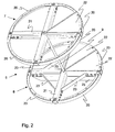
- a perspective view of a cleaning device according to the invention.
In Figur 1 ist ein Schacht 1 schematisch dargestellt. Der Schacht 1 besteht
beispielsweise aus Betonringen, welche übereinandergestapelt sind oder aus
einem monolithisch hergestellten Schacht und befindet sich vollständig im
Boden 2. Für eine zuverlässige Reinigung des gesamten zufließenden Wassers
muß der Schacht 2 nach außen wasserdicht sein. Während der eigentl i-che
Schachtbereich in dem vorliegenden Ausführungsbeispiel aus zylindrischen
Ringsegmenten 3 besteht, ist der Abschluß des Schachtes aus einem
konischen Ringsegment 4 gebildet. Das konische Ringsegment 4 weist an
seinem einen Ende ein Mannloch 5 auf, welches üblicherweise mit einem
Deckel verschlossen ist, bei Bedarf jedoch zum Einstieg von Servicepersonal
geöffnet werden kann.In Figure 1, a
In dem Schacht 1 ist eine vorzugsweise aus Edelstahl hergestellte Reinigungsvorrichtung
6 angeordnet. Die Reinigungsvorrichtung 6 besteht aus
einer oberen Siebplatte 7 und einer unteren Siebplatte 8. Die beiden
Siebplatten 7, 8 sind mit einem Abstandhalter 9 miteinander verbunden. Zwischen
den Siebplatten 7 und 8 ist ein körniger Ionenaustauscher 10 angeordnet.
Der Ionenaustauscher 10 ist ein Zeolith, insbesondere ein Klinoptilolith
oder ein Chabasith/Phillipsit. Das Material des Ionenaustauschers ist in
definierten Körnungen, beispielsweise größer 0,7 mm zwischen den
Siebplatten 7 und 8 eingefüllt. Vor dem Einsatz des Ionenaustauschers wird
dieser beispielsweise mit einer Natriumchlorid-Lösung vorbehandelt. Hierdurch
wird die Ionenaustauschkapazität für Schwermetallionen, wie beispielsweise
Zink, Kupfer oder Blei erhöht. Die Vorbehandlung kann vor dem
Einfüllen in die Reinigungsvorrichtung erfolgen. Der Ionenaustauscher wird
hierfür mit der NaCI-Lösung gespült.In the
Die Reinigungsvorrichtung 6 ist gegenüber dem Schacht 1 mittels einer
Dichtung 11 abgedichtet. Es kann sich dabei um einen Silikonstreifen handeln,
der in den Zwischenrum zwischen der Vorrichtung 6 und dem Schacht
1 eingespritzt wurde oder beispielsweise auch um einen Dichtring, der bei
der Montage zwischen die Reinigungsvorrichtung 6 und dem Schacht eingebaut
wurde..The
Üblich ist eine Höhe der Vorrichtung 6 von etwa 50 bis 100 cm bei einem
Durchmesser des Schachtes 1 von etwa ebenfalls 100 cm. Besonders vorteilhaft
bei dieser Reinigungsvorrichtung 6 ist es, dass der gesamte Querschnitt
des Schachtes 1 für die Reinigung des Wassers zur Verfügung steht.Usual is a height of the
Unterhalb der Reinigungsvorrichtung 6 ist bei dem vorliegenden Ausführungsbeispiel
eine schematisch dargestellte Abtrenneinheit 12 angeordnet. In
der Abtrenneinheit 12 sammeln sich Partikel an. Aus der Abtrenneinheit 12
können sie mit einer Absaugeinrichtung, beispielsweise einer Vakuumpumpe,
welche mit einem Absaugrohr 13 verbunden ist, aus der Abtrenneinheit
12 entnommen werden. Im normalen Betrieb ist das Absaugrohr 13 abgeschlossen. Below the
Das Absaugrohr 13 dient gemäß der vorliegenden Erfindung hauptsächlich
auch zur Durchführung eines Regenerationsvorganges des lonenaustauschers
10. Regenerationsflüssigkeit wird hierfür von oben durch die Reinigungsvorrichtung
6 hindurch geströmt und macht den Ionenaustauscher wieder
aufnahmefähig für Schwermetallionen. Die Regenerationsflüssigkeit und
evtl. eine Spülflüssigkeit, z.B. klares Wasser, werden durch das Absaugrohr
13 aus dem Schacht 1 abgesaugt und können separat entsorgt werden.
Hierdurch wird einer der wesentlichen Vorteile der Erfindung erzielt, dass die
Regenerierung der Reinigungsvorrichtung 6 innerhalb des Schachtes 1 erfolgen
kann, ohne diese vorher aus dem Schacht 1 entnehmen zu müssen.The
In die Abtrenneinheit 12 ist ein Zuführrohr 15 integriert. Über das Zuführrohr
15 wird das Abwasser dem Schacht 1 und der Reinigungsvorrichtung 6 zugeleitet.
Das Zuführrohr 15 mündet tangential in die Abtrenneinheit 12. Da
die Filteranlage bei starken Regenereignissen oberhalb der Bemessungsregens
hydraulisch versagen könnte, ist ein nicht dargestellter Notüberlauf
häufig vorgesehen, so dass das Wasser direkt in eine Rigole bzw. einen
Wasserablauf 16 gelangen kann.In the
Das über das Zuführrohr 15 zugeführte verschmutzte Wasser strömt von
unten nach oben durch die Reinigungsvorrichtung 6 und nachdem ein bestimmter
Wasserstand erreicht wurde in eine Rohrrigole bzw. einen Wasserablauf
16. Der Wasserablauf 16 kann entweder das gereinigte Wasser in
das Grundwasser oder ein offenes Gewässer abgeben. Das Wasser kann
selbstverständlich auch für den Gebrauch im Haus, beispielsweise für die
Toilettenspülung oder zum Waschen verwendet werden, wofür der Wasserablauf
16 an das Hauswassersystem angeschlossen werden.The supplied via the
Figur 2 zeigt ein Beispiel einer Reinigungsvorrichtung 6, in perspektivischer
Darstellung. Die obere Siebplatte 7 und die untere Siebplatte 8 sind mit dem
Abstandhalter 9 beabstandet gehalten. Der Abstandhalter 9 ist eine Stange,
welche im Zentrum der beiden Siebplatten 7 und 8 angeordnet ist und mit
den Siebplatten 7 und 8 an ihrem jeweiligen Ende beispielsweise mit einer
Schraubverbindung verbunden ist. Die obere Siebplatte 7 weist eine Tragkonstruktion
aus vier Kreissegmenten 20 und einem Tragkreuz 21 auf. Auf
der Tragkonstruktion sind Segmente 22 befestigt, von welchen in der vorliegenden
Darstellung aus Übersichtlichkeitsgründen nur ein Segment 22 dargestellt
ist. Bei der kompletten Vorrichtung 6 sind acht derartiger Segmente
22 an der oberen Siebplatte 7 angeordnet, so daß die Siebplatte 7 aus den
Segmenten 22 gebildet ist. Die Kreissegmente 20, das Tragkreuz 21 und die
Segmente 22 sind miteinander verschraubt. Hierdurch ist es ermöglicht, daß
sie durch das Mannloch 5 in den Schacht 1 eingeführt und innerhalb des
Schachtes 1 montiert werden.Figure 2 shows an example of a
Die Siebsegmente 22 bestehen vorzugsweise aus einem Edelstahlsiebblech
mit Öffnungen, welche einerseits das Wasser hindurchtreten lassen und andererseits
den Ionenaustauscher zurückhalten. Die Maschenweite der Siebfläche
ist daher entsprechend des verwendeten Ionenaustauschers 10 gewählt.
Beispielsweise ist eine Maschenweite von kleiner 0,7 mm gewählt.The
Die untere Siebplatte 8 ist ebenso wie die obere Siebplatte 7 aufgebaut. Da
auf ihr das Gewicht des Ionenaustauschers 10 lastet, weist sie zusätzliche
Verstärkungen 23 auf, welche die Tragkonstruktion und die Siebsegmente 22
unterstützen.The
Die vorliegende Erfindung ist nicht auf die dargestellten Ausführungsbeispiele beschränkt. Andere Konstruktionen, bei welchen die Platten, zwischen denen der Ionenaustauscher angeordnet ist, aus mehreren Segmenten bestehen und hiermit problemlos in einem Schacht montiert werden können oder in dem Schacht regeneriert werden können, fallen ebenso unter die vorliegende Erfindung. Auch die Reinigung von Regenwasser, das von Straßen oder Parkplätzen abfließt, kann durch das Einbringen von adsorbierendem Material von organischen Verunreinigungen, wie sie beispielsweise von Fahrzeugen stammen, gereinigt werden. Das adsorbierende Material kann zusätzlich oder alternativ zu dem Ionenaustauscher in die erfindungsgemäße Vorrichtung eingebracht werden.The present invention is not limited to the illustrated embodiments limited. Other constructions in which the plates, between where the ion exchanger is arranged, consist of several segments and thus easily be mounted in a shaft or in which wells can be regenerated are also covered by the present invention Invention. Also, the cleaning of rainwater, by roads or parking lots can drain off, by introducing adsorbing Material of organic impurities, such as those of Vehicles come, be cleaned. The adsorbent material can additionally or alternatively to the ion exchanger in the inventive Device are introduced.
Claims (29)
Applications Claiming Priority (4)
| Application Number | Priority Date | Filing Date | Title |
|---|---|---|---|
| DE10347267 | 2003-10-11 | ||
| DE10347267 | 2003-10-11 | ||
| DE102004042390 | 2004-09-02 | ||
| DE102004042390A DE102004042390A1 (en) | 2003-10-11 | 2004-09-02 | Device and shaft for the decentralized treatment of water and method for this purpose |
Publications (2)
| Publication Number | Publication Date |
|---|---|
| EP1522525A1 true EP1522525A1 (en) | 2005-04-13 |
| EP1522525B1 EP1522525B1 (en) | 2007-04-11 |
Family
ID=34315014
Family Applications (1)
| Application Number | Title | Priority Date | Filing Date |
|---|---|---|---|
| EP04104931A Not-in-force EP1522525B1 (en) | 2003-10-11 | 2004-10-08 | Device and shaft for the decentralised treatment of water and corresponding process |
Country Status (3)
| Country | Link |
|---|---|
| EP (1) | EP1522525B1 (en) |
| AT (1) | ATE359238T1 (en) |
| DE (1) | DE502004003448D1 (en) |
Cited By (3)
| Publication number | Priority date | Publication date | Assignee | Title |
|---|---|---|---|---|
| ES2317812A1 (en) * | 2008-12-15 | 2009-04-16 | Amitech Spain, S.A. | Modular equipment of storm and/or retention tanks (Machine-translation by Google Translate, not legally binding) |
| EP2602014A1 (en) | 2011-12-09 | 2013-06-12 | Etablissements Georges David | Device and system for filtering rainwater |
| CN115253413A (en) * | 2022-05-23 | 2022-11-01 | 江苏通州二建建设工程集团有限公司 | Municipal works drainage structures |
Families Citing this family (1)
| Publication number | Priority date | Publication date | Assignee | Title |
|---|---|---|---|---|
| DE102016001526A1 (en) * | 2016-02-10 | 2017-08-10 | Qirui Huang | A system solution and waste treatment facility for hospital waste (waste, waste water and waste gas) |
Citations (4)
| Publication number | Priority date | Publication date | Assignee | Title |
|---|---|---|---|---|
| US5820762A (en) * | 1995-06-20 | 1998-10-13 | Bamer; Jonathan Michael | Filter insert for a storm drain |
| US20010035371A1 (en) * | 1998-12-22 | 2001-11-01 | Sonja Priggemeyer | Arrangement for removing heavy metal ions from roof runoff waters |
| NL1018789C2 (en) * | 2001-08-21 | 2002-01-22 | Moons & Van Hoof B V | Rain and spring water treatment device giving household quality water |
| DE10127553A1 (en) * | 2001-05-09 | 2002-11-21 | Friedhelm Sieker | Filter insert for road drains with gully shaft consists of cartridge with mineral and chemical additive content, fitted into shaft |
-
2004
- 2004-10-08 EP EP04104931A patent/EP1522525B1/en not_active Not-in-force
- 2004-10-08 DE DE502004003448T patent/DE502004003448D1/en active Active
- 2004-10-08 AT AT04104931T patent/ATE359238T1/en active
Patent Citations (4)
| Publication number | Priority date | Publication date | Assignee | Title |
|---|---|---|---|---|
| US5820762A (en) * | 1995-06-20 | 1998-10-13 | Bamer; Jonathan Michael | Filter insert for a storm drain |
| US20010035371A1 (en) * | 1998-12-22 | 2001-11-01 | Sonja Priggemeyer | Arrangement for removing heavy metal ions from roof runoff waters |
| DE10127553A1 (en) * | 2001-05-09 | 2002-11-21 | Friedhelm Sieker | Filter insert for road drains with gully shaft consists of cartridge with mineral and chemical additive content, fitted into shaft |
| NL1018789C2 (en) * | 2001-08-21 | 2002-01-22 | Moons & Van Hoof B V | Rain and spring water treatment device giving household quality water |
Non-Patent Citations (2)
| Title |
|---|
| KASTING U ET AL: "BODENFILTERANLAGEN ZUR REINIGUNG VON ABFLUESSEN STARK VERSCHMUTZTER VERKEHRSFLAECHEN AUSWAHL GEEIGNETER BODENSUBSTRATE SOIL FILTRATION PLANTS FOR THE TREATMENT OF EFFLUENTS FROM SEVERELY POLLUTED TRAFFIC AREAS", KA - ABWASSER, ABFALL, GFA, HENNEF, DE, vol. 48, no. 9, September 2001 (2001-09-01), pages 1274 - 1276,1278, XP001161600, ISSN: 1616-430X * |
| PICK V ET AL: "DEZENTRALE BEHANDLUNG DES NIEDERSCHLAGSABFLUSSES VON VERKEHRSFLAECHEN IN EINER MEHRSTUFIGEN SCHACHTANLAGE DECENTRALIZED TREATMENT OF STORMWATER RUNOFF FROM TRAFFIC AREAS IN A MULTI-STAGE SHAFT UNIT", KA - ABWASSER, ABFALL, GFA, HENNEF, DE, vol. 49, no. 3, March 2002 (2002-03-01), pages 312 - 320, XP001143210, ISSN: 1616-430X * |
Cited By (4)
| Publication number | Priority date | Publication date | Assignee | Title |
|---|---|---|---|---|
| ES2317812A1 (en) * | 2008-12-15 | 2009-04-16 | Amitech Spain, S.A. | Modular equipment of storm and/or retention tanks (Machine-translation by Google Translate, not legally binding) |
| EP2602014A1 (en) | 2011-12-09 | 2013-06-12 | Etablissements Georges David | Device and system for filtering rainwater |
| FR2983739A1 (en) * | 2011-12-09 | 2013-06-14 | Babaz Inov | DEVICE AND SYSTEM FOR FILTRATION OF RAINWATER |
| CN115253413A (en) * | 2022-05-23 | 2022-11-01 | 江苏通州二建建设工程集团有限公司 | Municipal works drainage structures |
Also Published As
| Publication number | Publication date |
|---|---|
| ATE359238T1 (en) | 2007-05-15 |
| EP1522525B1 (en) | 2007-04-11 |
| DE502004003448D1 (en) | 2007-05-24 |
Similar Documents
| Publication | Publication Date | Title |
|---|---|---|
| EP2769029B1 (en) | Drainage device | |
| WO2012031714A1 (en) | Filter device for a road gully | |
| DE102008007227A1 (en) | Plant for rainwater management | |
| DE202012011112U1 (en) | Device for cleaning polluted rainwater or the like in the street drain (drain) | |
| AT505081B1 (en) | DEVICE AND BAY FOR DECENTRAL TREATMENT OF WATER | |
| EP2659944B1 (en) | Filter assembly and method for installing the filter assembly | |
| EP1967657B1 (en) | Filter device for a cleaning system for water containing solid particles and/or dissolved pollutants | |
| DE102004042390A1 (en) | Device and shaft for the decentralized treatment of water and method for this purpose | |
| EP1522525B1 (en) | Device and shaft for the decentralised treatment of water and corresponding process | |
| DE202006006753U1 (en) | Filter cartridge for street storm water drain has coarse upper and fine lower filters over perforated plate | |
| DE3247944C2 (en) | Process for subsoil seepage of rainwater | |
| DE19533935C2 (en) | Waste water treatment device | |
| EP1710361A1 (en) | Multistepped filter cartridge for street gullies | |
| EP3730706B1 (en) | Storage / seepage system | |
| EP1927388A1 (en) | Rainwater manhole filter system | |
| DE102017108820A1 (en) | filter system | |
| AT410453B (en) | Water drainage system with filters which discharges to soil soak-away or cistern | |
| EP1741845A2 (en) | Method and device for purifying rain water | |
| DE102005044166A1 (en) | Purification of rainwater (especially on the streets) involves separation into streams with dirt content separated off by a process more intense than purely gravitational separation | |
| EP1855775A1 (en) | Method and device for the purification of rain drainage water | |
| DE102010013473B4 (en) | Wastewater treatment device and method | |
| DE3518840C2 (en) | ||
| DE202007003813U1 (en) | Filtering device for a cleaning system for contaminated with solid particles and / or dissolved pollutants water | |
| DE3329924A1 (en) | Device for the secondary treatment of waste water | |
| DE202020102717U1 (en) | Filter insert for use in street gullies for cleaning surface water to be drained through an underground sewer system |
Legal Events
| Date | Code | Title | Description |
|---|---|---|---|
| PUAI | Public reference made under article 153(3) epc to a published international application that has entered the european phase |
Free format text: ORIGINAL CODE: 0009012 |
|
| AK | Designated contracting states |
Kind code of ref document: A1 Designated state(s): AT BE BG CH CY CZ DE DK EE ES FI FR GB GR HU IE IT LI LU MC NL PL PT RO SE SI SK TR |
|
| AX | Request for extension of the european patent |
Extension state: AL HR LT LV MK |
|
| 17P | Request for examination filed |
Effective date: 20050720 |
|
| AKX | Designation fees paid |
Designated state(s): AT CH DE LI |
|
| GRAP | Despatch of communication of intention to grant a patent |
Free format text: ORIGINAL CODE: EPIDOSNIGR1 |
|
| GRAS | Grant fee paid |
Free format text: ORIGINAL CODE: EPIDOSNIGR3 |
|
| GRAA | (expected) grant |
Free format text: ORIGINAL CODE: 0009210 |
|
| AK | Designated contracting states |
Kind code of ref document: B1 Designated state(s): AT CH DE LI |
|
| REG | Reference to a national code |
Ref country code: CH Ref legal event code: EP |
|
| REF | Corresponds to: |
Ref document number: 502004003448 Country of ref document: DE Date of ref document: 20070524 Kind code of ref document: P |
|
| PLBE | No opposition filed within time limit |
Free format text: ORIGINAL CODE: 0009261 |
|
| STAA | Information on the status of an ep patent application or granted ep patent |
Free format text: STATUS: NO OPPOSITION FILED WITHIN TIME LIMIT |
|
| 26N | No opposition filed |
Effective date: 20080114 |
|
| PGFP | Annual fee paid to national office [announced via postgrant information from national office to epo] |
Ref country code: AT Payment date: 20101026 Year of fee payment: 7 |
|
| PGFP | Annual fee paid to national office [announced via postgrant information from national office to epo] |
Ref country code: CH Payment date: 20101021 Year of fee payment: 7 Ref country code: DE Payment date: 20100827 Year of fee payment: 7 |
|
| REG | Reference to a national code |
Ref country code: CH Ref legal event code: PL |
|
| PG25 | Lapsed in a contracting state [announced via postgrant information from national office to epo] |
Ref country code: CH Free format text: LAPSE BECAUSE OF NON-PAYMENT OF DUE FEES Effective date: 20111031 Ref country code: LI Free format text: LAPSE BECAUSE OF NON-PAYMENT OF DUE FEES Effective date: 20111031 Ref country code: DE Free format text: LAPSE BECAUSE OF NON-PAYMENT OF DUE FEES Effective date: 20120501 |
|
| REG | Reference to a national code |
Ref country code: DE Ref legal event code: R119 Ref document number: 502004003448 Country of ref document: DE Effective date: 20120501 |
|
| REG | Reference to a national code |
Ref country code: AT Ref legal event code: MM01 Ref document number: 359238 Country of ref document: AT Kind code of ref document: T Effective date: 20111008 |
|
| PG25 | Lapsed in a contracting state [announced via postgrant information from national office to epo] |
Ref country code: AT Free format text: LAPSE BECAUSE OF NON-PAYMENT OF DUE FEES Effective date: 20111008 |