EP1522462A2 - Input device for multifunctional vehicle equipment - Google Patents
Input device for multifunctional vehicle equipment Download PDFInfo
- Publication number
- EP1522462A2 EP1522462A2 EP04008636A EP04008636A EP1522462A2 EP 1522462 A2 EP1522462 A2 EP 1522462A2 EP 04008636 A EP04008636 A EP 04008636A EP 04008636 A EP04008636 A EP 04008636A EP 1522462 A2 EP1522462 A2 EP 1522462A2
- Authority
- EP
- European Patent Office
- Prior art keywords
- dial
- input device
- dials
- informing
- input
- Prior art date
- Legal status (The legal status is an assumption and is not a legal conclusion. Google has not performed a legal analysis and makes no representation as to the accuracy of the status listed.)
- Granted
Links
Images


Classifications
-
- B—PERFORMING OPERATIONS; TRANSPORTING
- B60—VEHICLES IN GENERAL
- B60K—ARRANGEMENT OR MOUNTING OF PROPULSION UNITS OR OF TRANSMISSIONS IN VEHICLES; ARRANGEMENT OR MOUNTING OF PLURAL DIVERSE PRIME-MOVERS IN VEHICLES; AUXILIARY DRIVES FOR VEHICLES; INSTRUMENTATION OR DASHBOARDS FOR VEHICLES; ARRANGEMENTS IN CONNECTION WITH COOLING, AIR INTAKE, GAS EXHAUST OR FUEL SUPPLY OF PROPULSION UNITS IN VEHICLES
- B60K35/00—Instruments specially adapted for vehicles; Arrangement of instruments in or on vehicles
- B60K35/10—Input arrangements, i.e. from user to vehicle, associated with vehicle functions or specially adapted therefor
Definitions
- the present invention relates to an input device actuated without being looked at and an automobile vehicle using the input device.
- Switch devices 8, 9 are each constructed of rotary dial knob (hereinafter called "knob") 12 incorporating a rotary encoder therein and display 13 disposed in the center thereof. Although it is not shown, switch devices 8, 9 each has a built-in tact switch.
- FIG. 8 shows a state in which the function of air conditioner's temperature setting is switch-selected.
- display 13 displays the currently established function and the current set value.
- FIG. 8 there are displayed “TEMP” representing the function of temperature setting and "25.0” indicating the set temperature. It is arranged such that the input function causes the temperature to be changed by having knob 12 rotated in a direction. In other words, by turning knob 12, the temperature can be changed at will.
- knob 12 is completely circular in shape and the driver makes inputting of the driving direction by means of a rotary encoder. Since the rotary encoder freely rotates 360°, it is impossible for the driver to know what the currently set value is only by touching the switch. This means that the driver is required to look at display 13. Although such an advantage can be obtained that the number of switches is reduced, the driver is unable to make the control with his or her eyes turned away from the switches. Thus, it is impossible for the driver to manipulate the switch safely and certainly only with the touch of a hand on the switch.
- Input device of the present invention has a plurality of dials, a driving portion for moving the dials, a dial selecting portion, and a controller.
- the dial selecting portion receives an input to make a selection from the plurality of dials.
- the controller controls the driving portion such that the dial selected by the input supplied to the dial selecting portion is moved to a predetermined position.
- FIG. 1 is a schematic front view of an input device as an exemplary embodiment of the present invention in its state having selected a temperature setting dial.
- FIG. 2 is a schematic front view of the same input device in its state having selected an air vent switching dial.
- FIG. 3A is a schematic sectional view showing the surroundings of a rotary plate of the input device.
- FIG. 3B is a block diagram showing the input device and vehicle-mounted equipments.
- FIG. 4 is a circuit diagram for transmitting a dial position signal in the input device.
- FIG. 5 is a schematic sectional view showing details of a dial on the input device.
- Rotary disk 21 is provided with dials 22, 23, 24 and 25.
- dials 22, 23, 24 and 25 By this arrangement, each of a plurality of the dials can be easily shifted to a predetermined position.
- Dial 22 for setting the temperature of the air conditioner is disposed on the inner side of display plate 26 displaying temperatures.
- Dial 23 for setting the air vent of the air conditioner is disposed on the inner side of display plate 27 displaying air vents.
- Dial 24 for setting the sound level of the audio equipment is disposed on the inner side of display plate 28 displaying sound levels.
- Dial 25 for setting the air flow of the air conditioner is disposed on the inner side of display plate 29 displaying air flows.
- Display plates 26, 27, 28 and 29 are arranged to be oriented in a fixed direction regardless of the angular positions of rotary disk 21.
- press switch 75 hereinafter called "switch" 75.
- a press on dial 23 actuates switch 75. Otherwise, switch 75 may be disposed on the top side of dial 23 so as to be actuated directly
- Protrusions 30 are provided at a portion of dial 22, 23, 24 and 25 in their diametrical directions.
- Light emitting portions 31 are provided at a portion of dial 22, 23, 24 and 25, which are turned on to allow a passenger at the front passenger seat to operate the input device with ease when it is dark inside the automobile while the driver drives the automobile with the headlights on. Otherwise, the light is automatically turned on when it becomes dark. This also minimizes the time required for the driver to move his or her line of sight and, hence, contributes to improvement in safety.
- Light emitting portion 31, made of a light emitting diode, lamp, or fluorescent member, is a first angle indicator indicating the angle of the dial with respect to the display plate.
- Shaft 32 has its one end connected with rotary plate 21 and the other end with gear 33.
- One end of gear 35 is rotatably coupled with annular member 34 provided with internal gear 39.
- the other end of gear 35 is connected with gear 36.
- Annular member 38 fixed to the automobile vehicle (not shown) has internal gear 37 in meshing engagement with gear 36.
- gear 33 is in meshing engagement with gear 35.
- gear 33 is rotated, its rotation is transmitted to gear 36 through gear 35. Since internal gear 37 is in meshing engagement with gear 36 and member 38 is fixed, the aforesaid rotation causes member 34 to rotate beneath rotary plate 21 coaxially with rotary plate 21.
- Gear 40 connected with display plate 29 is in meshing engagement with internal gear 39 of member 34. Because of rotating of member 34 with internal gear 39 thereof in meshing engagement with gear 40, display plate 29 moves with its orientation kept fixed when rotary plate 21 rotates.
- Rotary mechanism made up of a combination of such gears as gears 33, 35, 36 and 40 and members 34 and 38 having internal gears 37 and 39 is operated by power of motor 41, an only one driving portion. In this arrangement, the dial and the display plate are allowed to move by means of a small number of members.
- Display plates 26, 27 and 28 also move with their orientations kept fixed by similar mechanism.
- Dials 22, 23, 24 and 25 on display plates 26, 27, 28 and 29 also move with their orientations kept fixed.
- Motor 41 coupled with shaft 32, is a driving portion for rotating rotary plate 21 to move dials 22, 23, 24 and 25.
- Controller 42 is connected with dials 22, 23, 24and 25 and press switch 75.
- Controller 42 is also connected with motor 41, air conditioner 43, audio equipment 44, informing portion 45, dial selecting portion 46, and dial position detecting portion (hereinafter called "detector") 47.
- controller 42 controls air conditioner 43, controls audio equipment 44, updates images displayed by informing portion 45, and controls motor 41.
- display plates 26, 27, 28 and 29 each has circuit 48 incorporated therein.
- the resistance value of each resistor 49 included in circuit 48 is adapted to vary with the position of dial 22, 23, 24 and 25 with respect to each display plate 26, 27, 28 and 29.
- internal gear 71 is provided on display plate 27 and internal gear 71 is arranged in meshing engagement, via reduction gear 74, with gear 73 provided on operating shaft 72 of resistor 49 made of a variable resistor.
- the other display plates and dials are arranged in like manner.
- Each detector 47 disposed adjacent to dial 22, 23, 24 and 25 detects the change in the resistance value of resistor 49 through intercoil coupling.
- detector 47 detects a dial position in a noncontact manner and inputs it to controller 42.
- Input device 81 is configured as described above.
- FIG. 6 schematically shows the state of input device 81 mounted on a vehicle.
- Steering wheel 60 for steering the vehicle is provided inside car body 82 supported on drive wheels 83.
- meter panel 62 Forwardly of steering wheel 60, there is provided meter panel 62 and, between driver' s seat 84 and front passenger seat 85, there is provided center console 61.
- Input device 81 is provided at the upper portion of center console 61.
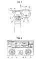
- FIG. 7 schematically shows the surroundings of the driver ' s seat.
- input device 81 is provided at the upper portion of center console 61 and dial selector 46 receives an input from steering switch 65 provided at a portion of steering wheel 60.
- This arrangement makes inputting from the driver to dial selector 46 easy and allows the driver to make selection of a function by a small stroke of finger movement even while driving the vehicle.
- Informing portion 45 for notifying the driver of the result of operation of input device 81 and the present status of the same allows images and characters to be displayed on display portion 63 made of a display.
- Display portion 63 is installed either at meter panel 62 or at the upper portion of center console 61.
- display portion 63 Since display portion 63 is located near windshield 69, the driver is enabled to verify the present status with a minimum movement of his or her line of sight while driving and this improves safety driving.
- head-up display 64 on which images are projected may be provided at a portion of windshield 69 as the display portion.
- FIG. 1 is a schematic diagram showing input device 81 when the driver, while driving a vehicle with a right-hand steering wheel, has selected a temperature setting function with the use of dial selector 46.
- dial 22 for the temperature setting is located at a predetermined position nearest to steering wheel 60.
- dial 22 is located at the upper right. Therefore, the driver is at a position easy to operate dial 22 and hence enabled to move his or her hand off steering wheel 60 and touch and operate dial 22 at once.
- a command signal therefor is transmitted to controller 42 by a press on an air vent switch at dial selector 46.
- Controller 42 causes motor 41 to operate so that dial 23 for setting up air vents is shifted to the position nearest to the driver as shown in FIG. 2.
- rotary plate 21 is rotated 90° by means of gear 33 and shaft 32 to the left as indicated by the arrow in FIG. 1, whereby display plates 26, 27, 28 and 29 and dials 22, 23, 24 and 25 are shifted in leftward rotating direction. Since rotary plate 21 is brought to a predetermined position fastest after the dial selection, the time for the driver to wait for completion of the rotation is reduced.
- Display plates 26, 27, 28 and 29 move without changing orientations of characters and graphics as viewed from the driver.
- Dials 22, 23, 24 and 25 also move without changing orientations of characters and pointed positions. Therefore, dials other than that in the predetermined position can be operated with their attitude kept the same as taken by each dial in the predetermined position. Further, it will not occur that a passenger at front passenger seat 85 feels difficulty in identifying them and makes an error in finding the position of protrusion 30.
- Such merits can be obtained by virtue of rotary mechanism composed of gears 35, 36 and 40, internal gears 37, 39, and membes 34, 38.
- protrusion 30 is a second angle indicator allowing the driver to know the angle of the dial with respect to the display plate through the sense of touch.
- the second angle indicator may otherwise be provided in the form of a recess.
- informing portion 45 displays a newly set item of control by means of display portion 63 or headup display 64.
- press switch 75 is actuated by pressing dial 23 and thereby switching may, for example, be made between introduction of outside air and circulation of inside air.
- other dials may also be provided with press switch 75 so that corresponding function is performed using the same.
- dial selection may also be made by means of voice recognition.
- voice recognition For example, when it is desired to change air vents, the driver speaks " air vent" into microphone 66 installed within the automobile. In response thereto, controller 42 activates motor 41 so that rotary plate 21 is rotated and dial 23 is shifted to the predetermined position. Thereby, the need for operating steering switch 65 can be eliminated and one searching motion by hand is reduced.
- voice recognition it may be considered to have commands for all the functions input by voice recognition, it is difficult to have a large number of words recognized by the present technology. Therefore, when voice recognition is to be used, its application may preferably be limited to limited words as used in dial selection.
- informing portion 45 allows operated results of dials 22, 23, 24 and 25 to be displayed. Instead of that, operation results may be announced by a voice output from voice output portion 67 formed of a speaker provided within the automovile. In this case, the need for checking the operation results on the screen is eliminated and hence safety is further improved.
- the predetermined position where one of dials 22, 23, 24and 25 is disposed is described to be at the upper right of rotary plate 21. However, it may be changed to the upper left position in the case of a vehicle with a left-hand steering wheel or it may be arranged to be changeable to any position that suits to the preference of users.
- detector 47 detects the position by means of coupling between coils in the present embodiment, another non-contact method or contact method may be used.
- controller 42, dial selecting portion 46 and informing portion 45 are provided separately. Since they are formed of microprocessors, two or more of them may be formed in one piece.
- Dial 24 is for controlling the sound level and the sound level can be acknowledged through the sense of hearing. Hence, the angle indicator therefor may be omitted.
- the input device moves a dial selected by the driver to a predetermined position near the steering wheel. Therefore, the need can be eliminated for the driver to search for a dial to be controlled by moving his or her line of sight. Since the driver is enabled to set a dial without looking at it, the input device of the invention is specifically useful for a vehicle in which setting of a dial is required without looking at the input device.
Landscapes
- Engineering & Computer Science (AREA)
- Chemical & Material Sciences (AREA)
- Combustion & Propulsion (AREA)
- Transportation (AREA)
- Mechanical Engineering (AREA)
- Instrument Panels (AREA)
- Switches With Compound Operations (AREA)
- Input From Keyboards Or The Like (AREA)
- Mechanical Control Devices (AREA)
- Air-Conditioning For Vehicles (AREA)
Abstract
Description
Claims (18)
- Input device comprising:a plurality of dials;a driving portion for moving the plurality of dials;a dial selecting portion for receiving an input to make a selection from the plurality of dials; anda controller for controlling the driving portion such that the dial selected by the input supplied to the dial selector is moved to a predetermined position.
- The input device according to claim 1, further comprising a rotary plate having the plurality of dials disposed thereon, wherein
the driving portion rotates the rotary plate. - The input device according to claim 2, wherein
the rotary plate rotates in such a direction that the selected dial takes the shortest distance to reach the predetermined position. - The input device according to claim 2, further comprising a rotation mechanism for rotating the plurality of dials such that orientations of the plurality of dials are kept fixed regardless of rotational angles of the rotary plate.
- The input device according to claim 4, wherein
the rotation mechanism is made up of a combination of a plurality of gears operated by a power from the driving portion. - The input device according to claim 1, wherein
at least one of the dials has an angle indicating portion showing an angle of the dial. - The input device according to claim 6, wherein
the angle indicating portion allows the angle of the dial to be known through a sense of touch. - The input device according to claim 6, wherein
the angle indicating portion is one of a protrusion and a recess provided in a diametrical direction of the dial. - The input device according to claim 6, wherein
the angle indicating portion is a light emitting portion. - The input device according to claim 1, further comprising a press switch disposed on one of:(1) at least one of undersides of the plurality of dials, and(2) at least one of upper sides of the plurality of dials.
- The input device according to claim 1, further comprising an informing portion for informing of results of operation of the selected dial.
- The input device according to claim 11, further comprising a press switch disposed on one of:(1) at least one of undersides of the plurality of dials, and(2) at least one of upper sides of the plurality of dials, wherein
the informing portion informs of results of operation of the press switch. - The input device according to claim 1, wherein
the dial selecting portion selects one of the plurality of dials through a voice recognition input. - A vehicle comprising:a car body;a driving wheel for supporting the car body thereon; andan input device installed inside the car body comprising:a plurality of dials;a driving portion for moving the plurality of dials;a dial selecting portion for receiving an input to make a selection from the plurality of dials; anda controller for controlling the driving portion such that the dial selected by the input supplied to the dial selector is moved to a predetermined position.
- The vehicle according to claim 14, further comprising a steering wheel provided in the car body, wherein
the predetermined position is a position closest to the steering wheel. - The vehicle according to claim 14, wherein
the input device further comprises:an informing portion for informing results of operation of the selected dial; anda display portion for displaying information from the informing portion, whereinthe display portion is at least one of(1) a display disposed on one of a meter panel provided within the car body and a dashboard provided within the car body, and(2) a headup display arranged to have information from the informing portion displayed on a windshield fixed to the car body. - The vehicle according to claim 14, wherein
the input device further comprises:an informing portion for informing of results of operation of the selected dial; anda voice output portion for informing of information from the informing portion by voice. - The vehicle according to claim 14, further comprising a steering wheel including a steering switch, wherein
the dial selecting portion selects one of the plurality of dials upon receipt of an input from the steering switch.
Applications Claiming Priority (2)
| Application Number | Priority Date | Filing Date | Title |
|---|---|---|---|
| JP2003351998A JP2005115822A (en) | 2003-10-10 | 2003-10-10 | Input device and automobile using the same |
| JP2003351998 | 2003-10-10 |
Publications (3)
| Publication Number | Publication Date |
|---|---|
| EP1522462A2 true EP1522462A2 (en) | 2005-04-13 |
| EP1522462A3 EP1522462A3 (en) | 2005-05-25 |
| EP1522462B1 EP1522462B1 (en) | 2008-09-17 |
Family
ID=34309284
Family Applications (1)
| Application Number | Title | Priority Date | Filing Date |
|---|---|---|---|
| EP04008636A Expired - Lifetime EP1522462B1 (en) | 2003-10-10 | 2004-04-08 | Input device for multifunctional vehicle equipment |
Country Status (4)
| Country | Link |
|---|---|
| US (1) | US7038147B2 (en) |
| EP (1) | EP1522462B1 (en) |
| JP (1) | JP2005115822A (en) |
| DE (1) | DE602004016605D1 (en) |
Families Citing this family (13)
| Publication number | Priority date | Publication date | Assignee | Title |
|---|---|---|---|---|
| ATE448108T1 (en) * | 2003-10-20 | 2009-11-15 | Volkswagen Ag | KNOB FOR A MOTOR VEHICLE |
| EP1696203A4 (en) * | 2003-11-28 | 2008-02-20 | Valeo Thermal Sys Japan Co | Rotary switch mechanism |
| JP2005203297A (en) * | 2004-01-19 | 2005-07-28 | Nissan Motor Co Ltd | Display type multi-function switch |
| US20060092129A1 (en) * | 2004-10-20 | 2006-05-04 | Visteon Global Technologies, Inc. | Human machine interface for vehicle |
| US7935070B2 (en) * | 2005-01-28 | 2011-05-03 | Fresenius Medical Care North America | Systems and methods for dextrose containing peritoneal dialysis (PD) solutions with neutral pH and reduced glucose degradation product |
| USD564974S1 (en) * | 2005-06-01 | 2008-03-25 | Delphi Technologies, Inc. | Switch design |
| JP4438769B2 (en) * | 2005-09-16 | 2010-03-24 | 株式会社デンソー | Steering switch device |
| US8039769B2 (en) * | 2006-09-19 | 2011-10-18 | Deere & Company | Joystick deactivation |
| KR100844660B1 (en) | 2006-12-13 | 2008-07-07 | 현대자동차주식회사 | Car Steering Wheel Remote Control |
| US7995038B2 (en) | 2007-09-28 | 2011-08-09 | GM Global Technology Operations LLC | Software flow control of rotary quad human machine interface |
| US9585810B2 (en) | 2010-10-14 | 2017-03-07 | Fresenius Medical Care Holdings, Inc. | Systems and methods for delivery of peritoneal dialysis (PD) solutions with integrated inter-chamber diffuser |
| JP5720224B2 (en) * | 2010-12-14 | 2015-05-20 | ヤマハ株式会社 | Switch structure, electronic component installation structure, and electronic musical instrument including the same |
| US10513183B2 (en) | 2016-12-16 | 2019-12-24 | Denso International America, Inc. | Tilt and turn dial |
Family Cites Families (13)
| Publication number | Priority date | Publication date | Assignee | Title |
|---|---|---|---|---|
| JPH10333764A (en) | 1997-06-02 | 1998-12-18 | Kojima Press Co Ltd | Multifunctional collective switch |
| JPH11329157A (en) * | 1998-05-21 | 1999-11-30 | Alps Electric Co Ltd | Switch device |
| JP3850619B2 (en) * | 1999-07-14 | 2006-11-29 | アルプス電気株式会社 | In-vehicle input device |
| US6441510B1 (en) * | 1999-08-17 | 2002-08-27 | Lear Corporation | Reconfigurable modular instrument cluster arrangement |
| DE19944324A1 (en) * | 1999-09-15 | 2001-03-22 | Audi Ag | Multi-function control device |
| JP4475796B2 (en) * | 2000-12-08 | 2010-06-09 | 株式会社東海理化電機製作所 | Equipment control device |
| US6812942B2 (en) * | 2000-12-28 | 2004-11-02 | International Business Machines Corporation | Context-responsive in-vehicle display system |
| EP1228917A1 (en) * | 2001-02-01 | 2002-08-07 | Pi Technology | A control arrangement |
| JP2002343193A (en) * | 2001-05-17 | 2002-11-29 | Calsonic Kansei Corp | Operating device for on-board equipment |
| JP3937765B2 (en) * | 2001-07-25 | 2007-06-27 | ティアック株式会社 | Switch device with indicator |
| JP2003054290A (en) | 2001-08-20 | 2003-02-26 | Denso Corp | Switch device for vehicles |
| US6961644B2 (en) * | 2002-12-12 | 2005-11-01 | Alps Automotive, Inc. | Dual haptic vehicle control and display system |
| US6903288B2 (en) * | 2003-02-12 | 2005-06-07 | Alps Automotive, Inc. | Dial-down switching system and method |
-
2003
- 2003-10-10 JP JP2003351998A patent/JP2005115822A/en active Pending
-
2004
- 2004-04-08 DE DE602004016605T patent/DE602004016605D1/en not_active Expired - Lifetime
- 2004-04-08 US US10/820,267 patent/US7038147B2/en not_active Expired - Lifetime
- 2004-04-08 EP EP04008636A patent/EP1522462B1/en not_active Expired - Lifetime
Also Published As
| Publication number | Publication date |
|---|---|
| DE602004016605D1 (en) | 2008-10-30 |
| US7038147B2 (en) | 2006-05-02 |
| EP1522462A3 (en) | 2005-05-25 |
| JP2005115822A (en) | 2005-04-28 |
| EP1522462B1 (en) | 2008-09-17 |
| US20050077157A1 (en) | 2005-04-14 |
Similar Documents
| Publication | Publication Date | Title |
|---|---|---|
| US7038147B2 (en) | Input device and automobile vehicle using the same | |
| EP1569073B1 (en) | Single knob multifunction controller and display unit | |
| JP2003054290A (en) | Switch device for vehicles | |
| US6418362B1 (en) | Steering wheel interface for vehicles | |
| US8581718B2 (en) | Motor vehicle | |
| CN102407776B (en) | Device for display of message | |
| KR20020092957A (en) | Arrangement for a switch-equipped steering wheel | |
| US20090128307A1 (en) | Display device and display method for a vehicle | |
| JPH1097821A (en) | Operating device and operating device for in-vehicle equipment using the same | |
| US20110130921A1 (en) | In-vehicle display system | |
| WO1998009848A1 (en) | Multi-functional control switch arrangement | |
| JP2009184406A (en) | Head-up display device for vehicle | |
| KR20130063911A (en) | Eye breakaway prevention system during vehicle's driving | |
| JP2000309232A (en) | Automobile with selection device | |
| JP2002225724A (en) | Operating device for in-vehicle equipment | |
| EP3659848B1 (en) | Operating module, operating method, operating system and storage medium for vehicles | |
| JP2002312047A (en) | Manual input device | |
| CN112673144B (en) | Synchronous switch for electric window | |
| US20170131792A1 (en) | Remote operation device | |
| WO2015141087A1 (en) | Operation device | |
| US12090853B2 (en) | Operating device for a motor vehicle and motor vehicle with an operating device | |
| JP2006264615A (en) | Vehicle display device | |
| JP2015105074A (en) | Display system for vehicle | |
| JP4501067B2 (en) | Vehicle information display device | |
| JP2005112027A (en) | Input switch and automobile and video photographing device using the same |
Legal Events
| Date | Code | Title | Description |
|---|---|---|---|
| PUAI | Public reference made under article 153(3) epc to a published international application that has entered the european phase |
Free format text: ORIGINAL CODE: 0009012 |
|
| PUAL | Search report despatched |
Free format text: ORIGINAL CODE: 0009013 |
|
| AK | Designated contracting states |
Kind code of ref document: A2 Designated state(s): AT BE BG CH CY CZ DE DK EE ES FI FR GB GR HU IE IT LI LU MC NL PL PT RO SE SI SK TR |
|
| AX | Request for extension of the european patent |
Extension state: AL HR LT LV MK |
|
| RIC1 | Information provided on ipc code assigned before grant |
Ipc: 7B 60K 37/06 B Ipc: 7B 60R 16/02 A |
|
| AK | Designated contracting states |
Kind code of ref document: A3 Designated state(s): AT BE BG CH CY CZ DE DK EE ES FI FR GB GR HU IE IT LI LU MC NL PL PT RO SE SI SK TR |
|
| AX | Request for extension of the european patent |
Extension state: AL HR LT LV MK |
|
| 17P | Request for examination filed |
Effective date: 20050909 |
|
| AKX | Designation fees paid |
Designated state(s): DE FR GB IT |
|
| GRAP | Despatch of communication of intention to grant a patent |
Free format text: ORIGINAL CODE: EPIDOSNIGR1 |
|
| GRAS | Grant fee paid |
Free format text: ORIGINAL CODE: EPIDOSNIGR3 |
|
| GRAA | (expected) grant |
Free format text: ORIGINAL CODE: 0009210 |
|
| AK | Designated contracting states |
Kind code of ref document: B1 Designated state(s): DE FR GB IT |
|
| REG | Reference to a national code |
Ref country code: GB Ref legal event code: FG4D |
|
| REF | Corresponds to: |
Ref document number: 602004016605 Country of ref document: DE Date of ref document: 20081030 Kind code of ref document: P |
|
| RAP2 | Party data changed (patent owner data changed or rights of a patent transferred) |
Owner name: PANASONIC CORPORATION |
|
| PLBE | No opposition filed within time limit |
Free format text: ORIGINAL CODE: 0009261 |
|
| STAA | Information on the status of an ep patent application or granted ep patent |
Free format text: STATUS: NO OPPOSITION FILED WITHIN TIME LIMIT |
|
| 26N | No opposition filed |
Effective date: 20090618 |
|
| GBPC | Gb: european patent ceased through non-payment of renewal fee |
Effective date: 20090408 |
|
| REG | Reference to a national code |
Ref country code: FR Ref legal event code: ST Effective date: 20091231 |
|
| PG25 | Lapsed in a contracting state [announced via postgrant information from national office to epo] |
Ref country code: FR Free format text: LAPSE BECAUSE OF NON-PAYMENT OF DUE FEES Effective date: 20091222 Ref country code: GB Free format text: LAPSE BECAUSE OF NON-PAYMENT OF DUE FEES Effective date: 20090408 |
|
| PG25 | Lapsed in a contracting state [announced via postgrant information from national office to epo] |
Ref country code: IT Free format text: LAPSE BECAUSE OF NON-PAYMENT OF DUE FEES Effective date: 20090408 |
|
| PGFP | Annual fee paid to national office [announced via postgrant information from national office to epo] |
Ref country code: DE Payment date: 20130403 Year of fee payment: 10 |
|
| REG | Reference to a national code |
Ref country code: DE Ref legal event code: R119 Ref document number: 602004016605 Country of ref document: DE |
|
| REG | Reference to a national code |
Ref country code: DE Ref legal event code: R119 Ref document number: 602004016605 Country of ref document: DE Effective date: 20141101 |
|
| PG25 | Lapsed in a contracting state [announced via postgrant information from national office to epo] |
Ref country code: DE Free format text: LAPSE BECAUSE OF NON-PAYMENT OF DUE FEES Effective date: 20141101 |