EP1522419A1 - Device for the automatic inserting of products into envelopes - Google Patents
Device for the automatic inserting of products into envelopes Download PDFInfo
- Publication number
- EP1522419A1 EP1522419A1 EP04077540A EP04077540A EP1522419A1 EP 1522419 A1 EP1522419 A1 EP 1522419A1 EP 04077540 A EP04077540 A EP 04077540A EP 04077540 A EP04077540 A EP 04077540A EP 1522419 A1 EP1522419 A1 EP 1522419A1
- Authority
- EP
- European Patent Office
- Prior art keywords
- conveyor belt
- envelope
- envelopes
- products
- sheets
- Prior art date
- Legal status (The legal status is an assumption and is not a legal conclusion. Google has not performed a legal analysis and makes no representation as to the accuracy of the status listed.)
- Granted
Links
Images


Classifications
-
- B—PERFORMING OPERATIONS; TRANSPORTING
- B43—WRITING OR DRAWING IMPLEMENTS; BUREAU ACCESSORIES
- B43M—BUREAU ACCESSORIES NOT OTHERWISE PROVIDED FOR
- B43M5/00—Devices for closing envelopes
- B43M5/04—Devices for closing envelopes automatic
- B43M5/042—Devices for closing envelopes automatic for envelopes with only one flap
-
- B—PERFORMING OPERATIONS; TRANSPORTING
- B43—WRITING OR DRAWING IMPLEMENTS; BUREAU ACCESSORIES
- B43M—BUREAU ACCESSORIES NOT OTHERWISE PROVIDED FOR
- B43M3/00—Devices for inserting documents into envelopes
- B43M3/04—Devices for inserting documents into envelopes automatic
- B43M3/045—Devices for inserting documents into envelopes automatic for envelopes with only one flap
Definitions
- the present invention refers to a device for the automatic inserting of products into envelopes.
- the problems currently encountered concern the fact that the thrusters do not easily feed the printed product or sheet, made from light material, since the printed product or sheet tends to fold or jam, becoming ruined during the course of the thrusting introduction operation. Moreover, it is not always possible to carry out both a complete and satisfactory opening of the envelope to allow the introduction of the printed product or of the sheet and a suitable timing of feeding of the printed product or sheet into the envelope, when it is suitably opened.
- the general purpose of the present invention is that of identifying and making a device for the automatic inserting of products into envelopes that allows all of the aforementioned technical problems to be solved.
- Another purpose of the invention is that of making a device for the automatic inserting of products into envelopes of the type indicated above that works in the presence of large thicknesses and sizes of the printed product or sheet, without any problem.
- Another purpose of the invention is that of making a device for the automatic inserting of products into envelopes that allows a substantial saving of inserting of products into envelopes time to be attained, whilst still carrying out a correct and precise arrangement of any printed product or sheet inside each envelope.
- Yet another purpose is that of identifying a device that makes the execution of the inserting of products into envelopes operations as automatic and quick as possible.
- a solution is thus achieved for always correct inserting of printed product or of sheets into envelopes that arrive one after the other spaced apart on a conveyor belt, unloaded by feeders or similar devices, which allow their insertion into each single envelope, also fed by a device similar to a feeder.
- a device 11 for the automatic inserting of one or more products into envelopes, such as printed product or sheets 12, according to the present invention, into individual envelopes 13 is shown.
- the printed product or sheets 12 are fed, in the predetermined number, between a pair of conveyor belts 14 and 15 and are arranged in one or more feeders (not shown) positioned upstream of the inserting of products into envelopes device 11.
- the envelopes 13, on the other hand, are arranged in a pile in a storage container 16 situated above the conveyor belts 14 and 15.
- a gripping element such as at least one suction cup 17
- This conveyor belt 20 at the top faces a further conveyor belt 21 so as to define a feeding group of the envelope 13 towards the inserting of products into envelopes zone.
- a nozzle 22 is arranged that supplies a blow of air, schematised at 23, towards the envelope partially locked between the two conveyor belts 20 and 21.
- the blow of air 23 emitted by the nozzle 22 licks the outer surface of the envelope 13 and makes a closing tab 24 of the envelope open in rotation and flip back to free a mouth of the envelope.
- An end of the conveyor belt 14 is arranged to wind between a pair of rollers 25 and 26 on which the aforementioned conveyor belt winds in an S-shape.
- the two rollers 25, 26, with respect to the other rollers on which the conveyor belt winds that are able to rotate but not translate, are arranged on a displaceable cursor 27 so that they an slide horizontally below the upper branch of the conveyor belt 14 that supports and advances both the printed products or sheets 12 and the individual envelopes 13. More specifically, such a cursor 27 is commanded into a movement forwards and backwards on a guide 28 through a connecting rod 29.
- the connecting rod 29 at one end is hinged at 30 to the cursor 27 and at the other end is hinged at 31 to a rotating disc 32 commanded into rotation by a respective motor reducer 33 with interposition of a transmission 34.
- An end 37 of the conveyor belt 14 that can move forwards and backwards is thus made.
- a sucked conveyor belt 35 is arranged, for example made through a belt provided with holes, which in an upper branch thereof slides above suction cases 36 in which the vacuum is made.
- Such a sucked conveyor belt 35, together with the displaceable end 37 of the conveyor belt 14 define an opening 38 of variable size in which, as described hereafter, the tab 24 of the envelope 13 is arranged.
- a lower suction cup 39 is arranged that acts as a gripping element of the tab 24 of the envelope thanks to the fact that it is connected to a vacuum source.
- an upper suction cup 40 is arranged, also connected to a vacuum source, which acts as a gripping element and opening element of the mouth of the envelope 13.
- the lower suction cup 39 and the upper suction cup 40 are actuated in their movement towards and away from the tab 24 and the mouth of the envelope 13, respectively, through respective motor reducers 41 and 42.
- These motor reducers 41 and 42 indeed, command leverism transmissions 43 and 44 that carry the suction cups 39 and 40 at their ends.
- two mobile introducers 45 are foreseen that consist of two 90° sectors or portions, which can be identified in a quarter circumference, arranged oscillating through respective motors 46 on supports 47.
- Such introducers 45 can be inserted above the tab 24 of the envelope, when open, and inside the mouth of the envelope at opposite sides and at the same end of the mouth itself, as shown in figure 11.
- the oscillation of such introducers 45 is commanded by the motors 46 with interposition of articulated parallelograms 53.
- the supports 47 of the introducers can in turn be displaced towards and away from the sucked conveyor belt 35 in an essentially vertical plane, in other words towards and away from the mouth of the envelope 13 that is arranged on it.
- Such vertical displacement is commanded by a motor reducer 48 and by a leverism 49 placed between it and the supports 47.
- a hatch schematised at 50, is also arranged for getting rid of envelopes 13 with printed products or sheets 12 not completely inserted or inserted in the incorrect amount or else envelopes that have partially broken during the inserting of products into envelopes operation.
- a second hatch, schematised at 51, is arranged upstream of the conveyor belt 14 and 15 for getting rid of printed product or sheets 12 supplied in double the amount or of unsuitable sizes fed by the feeders or not fully released from such feeders (not shown) arranged upstream of the inserting of products into envelopes device.
- a group 52 for flipping back and closing the envelope that also takes care of moistening the tab 24 of each envelope and arranging it to close the envelope over the mouth.
- the printed product or sheets 12 are fed one after the other in the predetermined number by one or more feeders (not shown), arranged upstream of the inserting of products into envelopes device 11, between a pair of conveyor belts 14 and 15.
- the envelopes 13 are also fed one after the other being picked up from the storage container 16 through the gripping element, in other words the suction cup 17 applied to the arm 18 oscillating about the pin 19.
- each envelope 13 with the tab 24 opened by the blow 23 of the nozzle 22 is introduced between the conveyor belts 20 and 21 that face each other to define the feeding group of the envelope 13 towards the inserting of products into envelopes zone to receive one or more printed products according to the predetermined number.
- the envelope itself is advanced towards and above the sucked conveyor belt 35, whereas the displaceable end 37 of the conveyor belt 14 is pull backwards to define the opening 38 by the return of the cursor 27.
- the immediately subsequent step sees the end of the arrangement of the envelope 13 above the sucked conveyor belt and the continuation of the backward movement of the displaceable end 37 with simultaneous advancing of the printed product 12. Also simultaneously, the downwards movement of the upper suction cup 40, the upwards movement of the lower suction cup 39 and the downward movement of the mobile introducers 45, or rather of their supports 47, begins through the activation of the respective motors 42, 41 and 48 and leverisms 44, 43 and 49.
- the empty envelope 13 is thus completely arranged over the sucked conveyor belt 35 and locked onto it through the stopping of the conveyor belt itself 35.
- the upper suction cup 40 then reaches the mouth of the envelope 13, grips it, since a vacuum has been created inside it, and starts an upward movement.
- the lower suction cup 39 reaches the tab 24 of the envelope 13, grips it, since a vacuum has been created inside it, and starts a downward movement for it to be flipped back in the opening 38.
- the introducers 45 once their downward movement over the tab 24 of the envelope is complete, start their rotation to go inside the envelope or rather its opening through the activation of the motor 46.
- the upper suction cup 40 finishes its upward movement completely opening the mouth of the envelope whereas the lower suction cup 39 finishes its downward movement lowering the tab 24 under the arrival plane of the printed product 12 and under the displaceable end 37 of the conveyor belt 14.
- the introducers 45 finish rotating inside the envelope 13 making a secure invitation for the printed product or sheet 12 that advances fed by the displaceable end 37 of the conveyor belt 14 that advances to close the opening 38.
- the printed product or sheet 12 thanks to the continuous advance of the displaceable end 37, is introduced into the envelope 13 that is still stationary since the sucked conveyor belt 35 is still immobile.
- Another subsequent empty envelope 13 is arranged between the conveyor belts 21 and 14 ready to receive a respective printed product or sheet 12.
- the variation in advancing speed of the conveyor belts, as well as in activation of the further auxiliary devices, allows adjustment of the device according to the varying of the size of the envelopes used for inserting of products into envelopes.
- the device for the automatic inserting of products into envelopes made according to the present invention therefore does not have all the drawbacks that limited the functionality of known devices.
- the device for the automatic inserting of products into envelopes of the present invention thus conceived is susceptible to numerous modifications and variants, which are al covered by the invention itself.
Landscapes
- Supplying Of Containers To The Packaging Station (AREA)
- Container Filling Or Packaging Operations (AREA)
- Sheets, Magazines, And Separation Thereof (AREA)
- Feeding Of Articles By Means Other Than Belts Or Rollers (AREA)
- Basic Packing Technique (AREA)
- Packaging Of Special Articles (AREA)
- Control And Other Processes For Unpacking Of Materials (AREA)
- Vending Machines For Individual Products (AREA)
Abstract
Description
- The present invention refers to a device for the automatic inserting of products into envelopes.
- Currently, numerous machines that take care of the introduction of printed products or sheets in general into envelopes are foreseen. In these known machines the introduction of printed products or sheets is carried out through mechanical thrusters that act upon the rear part of them and introduce them into the envelope that is opened.
- These known apparatuses do not allow automatic inserting of products into envelopes at high speeds since they have limitations due both to the advance of the single envelope, and its opening, as well as above all due to the introduction into the envelope, once opened, of the printed product or of the preselected sheet.
- In particular, the problems currently encountered concern the fact that the thrusters do not easily feed the printed product or sheet, made from light material, since the printed product or sheet tends to fold or jam, becoming ruined during the course of the thrusting introduction operation. Moreover, it is not always possible to carry out both a complete and satisfactory opening of the envelope to allow the introduction of the printed product or of the sheet and a suitable timing of feeding of the printed product or sheet into the envelope, when it is suitably opened.
- All of these drawbacks mean extremely complex inserting of products into envelopes cycles carried out at low speeds, as well as the occurrence of possible stopping of the machine due to breaking of the envelope or part of it and/or due to folding of the printed product or sheets and their breaking.
- Therefore, the general purpose of the present invention is that of identifying and making a device for the automatic inserting of products into envelopes that allows all of the aforementioned technical problems to be solved.
- Another purpose of the invention is that of making a device for the automatic inserting of products into envelopes of the type indicated above that works in the presence of large thicknesses and sizes of the printed product or sheet, without any problem.
- Another purpose of the invention is that of making a device for the automatic inserting of products into envelopes that allows a substantial saving of inserting of products into envelopes time to be attained, whilst still carrying out a correct and precise arrangement of any printed product or sheet inside each envelope.
- Yet another purpose is that of identifying a device that makes the execution of the inserting of products into envelopes operations as automatic and quick as possible.
- These and other purposes according to the present invention are accomplished by realising a device for the automatic inserting of products into envelopes as outlined in the attached
claim 1. - Further relevant characteristics of the present invention are the object of the dependent claims.
- Through a device according to the present invention a solution is thus achieved for always correct inserting of printed product or of sheets into envelopes that arrive one after the other spaced apart on a conveyor belt, unloaded by feeders or similar devices, which allow their insertion into each single envelope, also fed by a device similar to a feeder.
- The functional and structural characteristics and the advantages of a device according to the invention shall become clearer from the description of a non-limiting embodiment thereof, with reference to the attached drawings, in which:
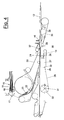
- figure 1 schematically shows, in a top side view, a device for the automatic inserting of products into envelopes according to the invention inside an inserting line of products into envelopes;
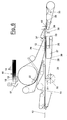
- figure 2 is an enlarged top side view of the inserting of products into envelopes device;
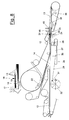
- figures 3-9 show schematic top views of the successive steps of the inserting of products into envelopes operation carried out through the device;
- figures 10 and 11 show top and plan views from above of introducing elements forming part of the device of the invention.
-
- With reference to the drawings, a
device 11 for the automatic inserting of one or more products into envelopes, such as printed product orsheets 12, according to the present invention, intoindividual envelopes 13 is shown. - The printed product or
sheets 12 are fed, in the predetermined number, between a pair ofconveyor belts envelopes device 11. Theenvelopes 13, on the other hand, are arranged in a pile in astorage container 16 situated above theconveyor belts suction cup 17, is arranged connected to a vacuum source, applied to anarm 18 oscillating about apin 19. which grips the individual envelope by sucking it and feeds it onto aconveyor belt 20. This conveyor belt 20 at the top faces a further conveyor belt 21 so as to define a feeding group of theenvelope 13 towards the inserting of products into envelopes zone. - In collaboration with the
conveyor belts 20 and 21 and with the gripping element 17-19 anozzle 22 is arranged that supplies a blow of air, schematised at 23, towards the envelope partially locked between the twoconveyor belts 20 and 21. The blow ofair 23 emitted by thenozzle 22 licks the outer surface of theenvelope 13 and makes aclosing tab 24 of the envelope open in rotation and flip back to free a mouth of the envelope. - An end of the
conveyor belt 14 is arranged to wind between a pair ofrollers rollers displaceable cursor 27 so that they an slide horizontally below the upper branch of theconveyor belt 14 that supports and advances both the printed products orsheets 12 and theindividual envelopes 13. More specifically, such acursor 27 is commanded into a movement forwards and backwards on aguide 28 through a connectingrod 29. The connectingrod 29 at one end is hinged at 30 to thecursor 27 and at the other end is hinged at 31 to a rotatingdisc 32 commanded into rotation by arespective motor reducer 33 with interposition of atransmission 34. Anend 37 of theconveyor belt 14 that can move forwards and backwards is thus made. - Aligned downstream of the conveyor belt 14 a sucked
conveyor belt 35 is arranged, for example made through a belt provided with holes, which in an upper branch thereof slides abovesuction cases 36 in which the vacuum is made. Such a suckedconveyor belt 35, together with thedisplaceable end 37 of theconveyor belt 14 define anopening 38 of variable size in which, as described hereafter, thetab 24 of theenvelope 13 is arranged. - At this opening 38, in the lower part of the advancing plane of the printed products or
sheets 12 and of theenvelopes 13, alower suction cup 39 is arranged that acts as a gripping element of thetab 24 of the envelope thanks to the fact that it is connected to a vacuum source. At the initial portion of the suckedconveyor belt 35, above it, anupper suction cup 40 is arranged, also connected to a vacuum source, which acts as a gripping element and opening element of the mouth of theenvelope 13. Thelower suction cup 39 and theupper suction cup 40 are actuated in their movement towards and away from thetab 24 and the mouth of theenvelope 13, respectively, throughrespective motor reducers command leverism transmissions suction cups - Moreover, two
mobile introducers 45 are foreseen that consist of two 90° sectors or portions, which can be identified in a quarter circumference, arranged oscillating throughrespective motors 46 onsupports 47.Such introducers 45 can be inserted above thetab 24 of the envelope, when open, and inside the mouth of the envelope at opposite sides and at the same end of the mouth itself, as shown in figure 11. The oscillation ofsuch introducers 45 is commanded by themotors 46 with interposition of articulatedparallelograms 53. - The
supports 47 of the introducers can in turn be displaced towards and away from the suckedconveyor belt 35 in an essentially vertical plane, in other words towards and away from the mouth of theenvelope 13 that is arranged on it. Such vertical displacement is commanded by amotor reducer 48 and by aleverism 49 placed between it and thesupports 47. - Downstream of the sucked conveyor belt 35 a hatch, schematised at 50, is also arranged for getting rid of
envelopes 13 with printed products orsheets 12 not completely inserted or inserted in the incorrect amount or else envelopes that have partially broken during the inserting of products into envelopes operation. - A second hatch, schematised at 51, is arranged upstream of the
conveyor belt sheets 12 supplied in double the amount or of unsuitable sizes fed by the feeders or not fully released from such feeders (not shown) arranged upstream of the inserting of products into envelopes device. - Finally, downstream of the actual inserting of products into envelopes zone, in other words after the
hatch 50 and the suckedconveyor belt 35, agroup 52 for flipping back and closing the envelope that also takes care of moistening thetab 24 of each envelope and arranging it to close the envelope over the mouth. - Hereafter, in particular with reference to the schematic figures that show the inserting of products into envelopes cycle, the operation of the device according to the present invention is described.
- As stated previously, in such an initial step of the inserting of products into envelopes cycle, the printed product or
sheets 12 are fed one after the other in the predetermined number by one or more feeders (not shown), arranged upstream of the inserting of products intoenvelopes device 11, between a pair ofconveyor belts envelopes 13 are also fed one after the other being picked up from thestorage container 16 through the gripping element, in other words thesuction cup 17 applied to thearm 18 oscillating about thepin 19. More specifically, eachenvelope 13 with thetab 24 opened by theblow 23 of thenozzle 22, is introduced between theconveyor belts 20 and 21 that face each other to define the feeding group of theenvelope 13 towards the inserting of products into envelopes zone to receive one or more printed products according to the predetermined number. - As shown by the figure illustrating the subsequent step, an
envelope 13 withtab 24 open followed by a printed product orsheet 12 in phase with it, arranged between theconveyor belt conveyor belt 14. In an immediately subsequent step the envelope itself is advanced towards and above the suckedconveyor belt 35, whereas thedisplaceable end 37 of theconveyor belt 14 is pull backwards to define theopening 38 by the return of thecursor 27. - The immediately subsequent step sees the end of the arrangement of the
envelope 13 above the sucked conveyor belt and the continuation of the backward movement of thedisplaceable end 37 with simultaneous advancing of the printedproduct 12. Also simultaneously, the downwards movement of theupper suction cup 40, the upwards movement of thelower suction cup 39 and the downward movement of themobile introducers 45, or rather of theirsupports 47, begins through the activation of therespective motors leverisms - The
empty envelope 13 is thus completely arranged over the suckedconveyor belt 35 and locked onto it through the stopping of the conveyor belt itself 35. Theupper suction cup 40 then reaches the mouth of theenvelope 13, grips it, since a vacuum has been created inside it, and starts an upward movement. Thelower suction cup 39 reaches thetab 24 of theenvelope 13, grips it, since a vacuum has been created inside it, and starts a downward movement for it to be flipped back in theopening 38. Theintroducers 45, once their downward movement over thetab 24 of the envelope is complete, start their rotation to go inside the envelope or rather its opening through the activation of themotor 46. - As the operating cycle of the device continues the
upper suction cup 40 finishes its upward movement completely opening the mouth of the envelope whereas thelower suction cup 39 finishes its downward movement lowering thetab 24 under the arrival plane of the printedproduct 12 and under thedisplaceable end 37 of theconveyor belt 14. Theintroducers 45 finish rotating inside theenvelope 13 making a secure invitation for the printed product orsheet 12 that advances fed by thedisplaceable end 37 of theconveyor belt 14 that advances to close theopening 38. - The printed product or
sheet 12, thanks to the continuous advance of thedisplaceable end 37, is introduced into theenvelope 13 that is still stationary since the suckedconveyor belt 35 is still immobile. - The end of the advancing movement of the
displaceable end 37 of theconveyor belt 14 carries out the complete insertion of the printed product into the envelope. It is at this point that the upper andlower suction cups conveyor belt 35 start moving again carrying theenvelope 13 on it with the printedproduct 12 completely and correctly inserted, which is fed to thegroup 52 for flipping back and closing the envelope. - Another subsequent
empty envelope 13 is arranged between theconveyor belts 21 and 14 ready to receive a respective printed product orsheet 12. - It should be highlighted that the conveyor belts of the device of the invention travel at a constant speed during their operation, with the exception of the sucked
conveyor belt 35 that stops and starts according to that which has been described previously. - The variation in advancing speed of the conveyor belts, as well as in activation of the further auxiliary devices, allows adjustment of the device according to the varying of the size of the envelopes used for inserting of products into envelopes.
- The device for the automatic inserting of products into envelopes made according to the present invention therefore does not have all the drawbacks that limited the functionality of known devices.
- The presence of the conveyor belts and the arrangement between them both of the printed product or sheets and of the envelopes, above all in the step of feeding the printed products into the envelopes, solves the problems deriving from the printed products thrusted in known devices. Indeed, all of the problems deriving from folding or breaking of the printed products or sheets in the thrusting step are eliminated thanks to the feeding guided by the pairs of conveyor belts.
- It is therefore clear how simply and easily a solution to the general problem quoted previously has been found according to the present invention.
- The device for the automatic inserting of products into envelopes of the present invention thus conceived is susceptible to numerous modifications and variants, which are al covered by the invention itself.
- Moreover, in practice the materials used, as well as their size and components, can be whatever according to the technical requirements.
Claims (14)
- Device (11) for the automatic inserting of products into envelopes, such as printed products or sheets (12) in individual envelopes (13), where the individual printed products or sheets (12) are fed by one or more feeders and the envelopes (13) are arranged piled up in a storage container (16) equipped with at least one gripping element (17, 18, 19), which grips and feeds a single envelope (13) between a first upper conveyor belt (20) and a first lower conveyor belt (21) facing each other to define a feeding group of the envelope (13) towards the inserting of products into envelopes zone, also foreseeing a second upper conveyor belt (15) and a second lower conveyor belt (14) facing each other to advance said printed products or sheets (12) one after the other, a nozzle (22) being associated with said first conveyor belts (20, 21) for opening and flipping back a tab (24) of the individual envelopes (13) taken out from the storage container (16), said second lower conveyor belt (14) foreseeing an end (37) that can move forwards and backwards with respect to a sucked conveyor belt (35) aligned downstream of said conveyor belt (14) to define an opening (38) of variable size, at said opening (38) being foreseen a gripping element (39) of said tab (24) and at an initial portion of said sucked conveyor belt (35) being foreseen a further gripping element (40) of a mouth of said envelope (13) locked onto said sucked conveyor belt (35) and mobile introducing elements (45) that can be inserted over said tab (24) and inside said mouth of the envelope.
- Device (11) according to claim 1, characterised in that said end (37) of said second lower conveyor belt (14) that can move backwards and forwards is made through a pair of rollers (25, 26) on which said conveyor belt winds in an S-shape that are arranged at the front of a cursor (27) capable of sliding horizontally below an upper branch of said second conveyor belt (14) that supports and advances both said printed products or sheets (12) and individual envelopes (13), whereas the remaining rollers on which the conveyor belt (14) winds are fixed with respect to the device.
- Device (11) according to claim 2, characterised in that said cursor (27) is commanded into movement forwards and backwards on a guide (28) through a connecting rod (29) one end of which is hinged (at 30) to the cursor (27), and the other end is hinged (at 31) to a rotating disc (32) that is motorised (at 33, 34).
- Device (11) according to claim 1, characterised in that said introducer elements comprise two 90° sectors or portions (45), which can be identified in a quarter circumference, arranged at opposite sides and at the end of the mouth itself.
- Device (11) according to claim 4, characterised in that said two sectors (45) are arranged on supports (47) and oscillate through respective motors (46).
- Device (11) according to claim 5, characterised in that said supports (47) can in turn move in an essentially vertical plane towards and away from said sucked conveyor belt (35), in other words towards and away from the mouth of the envelope (13), a motor reducer (48) and a leverism (49) placed between it and said supports (47).
- Device (11) according to claim 1, characterised in that said gripping element of said tab (24) comprises a lower suction cup (39) that is connected to a vacuum source.
- Device (11) according to claim 1, characterised in that said further gripping element of a mouth of said envelope (13) comprises an upper suction cup (40) that is connected to a vacuum source.
- Device (11) according to claim 7 or 8, characterised in that said gripping elements (39, 40) are actuated into their movement towards and away from the tab (24) and the mouth of the envelope (13), respectively, through motor reducers (41, 42) and leverism transmissions (43, 44).
- Device (11) according to claim 1, characterised in that said sucked conveyor belt (35) comprises a conveyor belt provided with holes, which in an upper branch thereof slides above suction cases (36) in which the vacuum is created.
- Device (11) according to claim 1, characterised in that said at least one gripping element that grips each individual envelope (13) from said storage container (16) comprises at least one suction cup (17), connected to a vacuum source, applied to an arm (18) oscillating about a pin (19).
- Device (11) according to claim 1, characterised in that downstream of the sucked conveyor belt (35) a hatch (50) is arranged to get rid of envelopes (13) with printed products or sheets (12) not completely inserted or inserted in the incorrect amount or else envelopes that have partially broken during the inserting of products into envelopes operation.
- Device (11) according to claim 1, characterised in that upstream of said second conveyor belts (14, 15) a second hatch (51) is arranged to get rid of printed products or sheets (12) fed in double the amount or of an unsuitable size fed by the feeders or not fully released from such feeders.
- Device (11) according to claim 1, characterised in that said first upper and lower conveyor belts (20 and 21, respectively) and said second upper and lower conveyor belts (15 and 14, respectively) travel at a constant speed during their operation, able to be adjusted according to the size of the envelope.
Priority Applications (3)
| Application Number | Priority Date | Filing Date | Title |
|---|---|---|---|
| PL04077540T PL1522419T3 (en) | 2003-09-19 | 2004-09-14 | Device for the automatic inserting of products into envelopes |
| SI200430803T SI1522419T1 (en) | 2003-09-19 | 2004-09-14 | Device for the automatic inserting of products into envelopes |
| CY20081100833T CY1108245T1 (en) | 2003-09-19 | 2008-08-06 | PROVISION FOR AUTOMATIC IMPORTATION OF PRODUCTS IN BAGS |
Applications Claiming Priority (2)
| Application Number | Priority Date | Filing Date | Title |
|---|---|---|---|
| IT001794A ITMI20031794A1 (en) | 2003-09-19 | 2003-09-19 | DEVICE FOR AUTOMATIC PACKAGING OF PRODUCTS. |
| ITMI20031794 | 2003-09-19 |
Publications (2)
| Publication Number | Publication Date |
|---|---|
| EP1522419A1 true EP1522419A1 (en) | 2005-04-13 |
| EP1522419B1 EP1522419B1 (en) | 2008-05-07 |
Family
ID=34308108
Family Applications (1)
| Application Number | Title | Priority Date | Filing Date |
|---|---|---|---|
| EP04077540A Not-in-force EP1522419B1 (en) | 2003-09-19 | 2004-09-14 | Device for the automatic inserting of products into envelopes |
Country Status (15)
| Country | Link |
|---|---|
| US (1) | US7047711B2 (en) |
| EP (1) | EP1522419B1 (en) |
| JP (1) | JP4494146B2 (en) |
| AT (1) | ATE394245T1 (en) |
| BR (1) | BRPI0403906A (en) |
| CA (1) | CA2482149C (en) |
| CY (1) | CY1108245T1 (en) |
| DE (1) | DE602004013506D1 (en) |
| DK (1) | DK1522419T3 (en) |
| ES (1) | ES2306956T3 (en) |
| HK (1) | HK1079159A1 (en) |
| IT (1) | ITMI20031794A1 (en) |
| PL (1) | PL1522419T3 (en) |
| PT (1) | PT1522419E (en) |
| SI (1) | SI1522419T1 (en) |
Families Citing this family (10)
| Publication number | Priority date | Publication date | Assignee | Title |
|---|---|---|---|---|
| FR2876058B1 (en) * | 2004-10-01 | 2008-04-18 | Gianfranco Passoni | METHOD FOR AUTOMATICALLY LOADING LOW-DIMENSIONAL PIECES, ESPECIALLY DOCUMENTS, AND DEVICE FOR IMPLEMENTING SAID METHOD |
| WO2007077720A1 (en) | 2005-12-28 | 2007-07-12 | Gunze Limited | Enveloping device |
| GB2470955A (en) * | 2009-06-12 | 2010-12-15 | Neopost Technologies | Document inserting apparatus |
| EP2480457A2 (en) | 2009-09-21 | 2012-08-01 | Inventnord APS | Apparatus for placing three dimensional objects in envelopes |
| WO2011138440A2 (en) * | 2010-05-07 | 2011-11-10 | Böwe Systec Gmbh | Apparatus and method for inserting one or more goods into a moveable cover |
| JP5587169B2 (en) * | 2010-12-28 | 2014-09-10 | 理想科学工業株式会社 | Enclosed sealing device and image forming system |
| CH710009A2 (en) * | 2014-08-22 | 2016-02-29 | Kern Ag | inserter |
| US10265999B2 (en) * | 2015-02-20 | 2019-04-23 | Dmt Solutions Global Corporation | Envelope inserter with variably activated suction cups |
| CH712495A1 (en) * | 2016-05-30 | 2017-11-30 | Kern Ag | Inserter. |
| CN112721467B (en) * | 2020-12-29 | 2022-04-26 | 武汉绎方信息工程有限公司 | Full-air-suction type turnover mechanism and printing device formed by same |
Citations (2)
| Publication number | Priority date | Publication date | Assignee | Title |
|---|---|---|---|---|
| WO2002087973A1 (en) * | 2001-04-26 | 2002-11-07 | Bell & Howell Mail And Messaging Technologies Company | Inserting apparatus and method with controlled, master cycle speed-dependent actuator operations |
| EP1332891A1 (en) * | 2002-02-01 | 2003-08-06 | Pitney Bowes Deutschland GmbH | Mail handling system |
Family Cites Families (9)
| Publication number | Priority date | Publication date | Assignee | Title |
|---|---|---|---|---|
| US4081096A (en) * | 1975-12-04 | 1978-03-28 | Union Carbide Corporation | Cantilevered belted bag loading method |
| DE2940600A1 (en) * | 1979-10-06 | 1981-04-16 | E.C.H. Will (Gmbh & Co), 2000 Hamburg | METHOD AND DEVICE FOR PACKING PAPER PACKS IN PRE-SHAPED CARTON |
| US4338762A (en) * | 1980-05-05 | 1982-07-13 | Pako Corporation | Photographic film insertion apparatus |
| US5211384A (en) * | 1989-04-14 | 1993-05-18 | Bell & Howell Company | Inserter with diverter for faulty members |
| US5081825A (en) * | 1990-12-31 | 1992-01-21 | Pitney Bowes Inc. | Envelope flap unfolder and enclosure inserter with jam-clearing access |
| US5651238A (en) * | 1993-07-02 | 1997-07-29 | Pitney Bowes Inc. | Apparatus and method for variable opening of envelopes |
| US5447015A (en) * | 1993-11-01 | 1995-09-05 | Pitney Bowes Inc. | High speed insertion device |
| US5642598A (en) * | 1995-12-26 | 1997-07-01 | Pitney Bowes Inc. | Collation feeding mechanism for envelope inserting machine |
| US6155031A (en) * | 1998-03-24 | 2000-12-05 | Sitma S.P.A. | Modular automatic envelope inserting machine |
-
2003
- 2003-09-19 IT IT001794A patent/ITMI20031794A1/en unknown
-
2004
- 2004-09-13 US US10/939,698 patent/US7047711B2/en active Active
- 2004-09-14 PL PL04077540T patent/PL1522419T3/en unknown
- 2004-09-14 EP EP04077540A patent/EP1522419B1/en not_active Not-in-force
- 2004-09-14 ES ES04077540T patent/ES2306956T3/en active Active
- 2004-09-14 DK DK04077540T patent/DK1522419T3/en active
- 2004-09-14 BR BR0403906-8A patent/BRPI0403906A/en not_active IP Right Cessation
- 2004-09-14 AT AT04077540T patent/ATE394245T1/en active
- 2004-09-14 PT PT04077540T patent/PT1522419E/en unknown
- 2004-09-14 DE DE602004013506T patent/DE602004013506D1/en active Active
- 2004-09-14 SI SI200430803T patent/SI1522419T1/en unknown
- 2004-09-16 CA CA2482149A patent/CA2482149C/en not_active Expired - Fee Related
- 2004-09-17 JP JP2004271220A patent/JP4494146B2/en not_active Expired - Fee Related
-
2005
- 2005-10-13 HK HK05109032A patent/HK1079159A1/en unknown
-
2008
- 2008-08-06 CY CY20081100833T patent/CY1108245T1/en unknown
Patent Citations (2)
| Publication number | Priority date | Publication date | Assignee | Title |
|---|---|---|---|---|
| WO2002087973A1 (en) * | 2001-04-26 | 2002-11-07 | Bell & Howell Mail And Messaging Technologies Company | Inserting apparatus and method with controlled, master cycle speed-dependent actuator operations |
| EP1332891A1 (en) * | 2002-02-01 | 2003-08-06 | Pitney Bowes Deutschland GmbH | Mail handling system |
Also Published As
| Publication number | Publication date |
|---|---|
| JP4494146B2 (en) | 2010-06-30 |
| US7047711B2 (en) | 2006-05-23 |
| US20050060966A1 (en) | 2005-03-24 |
| CA2482149A1 (en) | 2005-03-19 |
| CY1108245T1 (en) | 2014-02-12 |
| PT1522419E (en) | 2008-08-18 |
| PL1522419T3 (en) | 2008-11-28 |
| EP1522419B1 (en) | 2008-05-07 |
| DE602004013506D1 (en) | 2008-06-19 |
| HK1079159A1 (en) | 2006-03-31 |
| DK1522419T3 (en) | 2008-09-08 |
| BRPI0403906A (en) | 2005-05-24 |
| ATE394245T1 (en) | 2008-05-15 |
| JP2005162328A (en) | 2005-06-23 |
| CA2482149C (en) | 2011-08-30 |
| SI1522419T1 (en) | 2008-10-31 |
| ITMI20031794A1 (en) | 2005-03-20 |
| ES2306956T3 (en) | 2008-11-16 |
Similar Documents
| Publication | Publication Date | Title |
|---|---|---|
| US5251425A (en) | Enveloping device | |
| US5425533A (en) | Apparatus for assembly of a plurality of items of insert material into stacks on a conveyor | |
| US4079576A (en) | In-line inserter | |
| US4034658A (en) | Tray feeder system | |
| EP2149499B1 (en) | Empty bag supply method and apparatus | |
| US4373710A (en) | Apparatus for inserting supplementary material into newspaper jackets | |
| US4106260A (en) | Article folding and packaging system | |
| EP1522419B1 (en) | Device for the automatic inserting of products into envelopes | |
| GB2225979A (en) | Method and apparatus for securing clasps to envelopes | |
| GB2139176A (en) | Method and apparatus for inserting sheet material into envelopes | |
| JPS58104843A (en) | Feeder for pasteboard sheet | |
| JPH09504744A (en) | Envelope stuffing device | |
| CS526490A3 (en) | Apparatus for feeding semi-finished products from a magazine, particularly of packages | |
| JP3320032B2 (en) | Modular automatic envelope insertion machine | |
| US4141392A (en) | Apparatus for automatic insertion of valved bags on bag-filling machines | |
| US3988016A (en) | High speed in-line paper inserting apparatus and method | |
| US2355697A (en) | Sheet delivery mechanism | |
| JP2005162328A5 (en) | ||
| JP2809606B2 (en) | Apparatus for quickly feeding sheet inserts to the pusher conveyor of a packaging machine | |
| US4968017A (en) | Method and device for feeding signatures on to a sewing machine | |
| AU2014349198B2 (en) | Apparatus for inserting documents into envelopes and associated method | |
| AU2002301060B2 (en) | Device to assemble printed products by insertion | |
| JP3776150B2 (en) | Cylindrical film mounting method and apparatus | |
| JP2950167B2 (en) | Apparatus and method for fitting cylindrical film to fitting object | |
| US3698704A (en) | Folded newspaper opening mechanism for multiple section inserting machine |
Legal Events
| Date | Code | Title | Description |
|---|---|---|---|
| PUAI | Public reference made under article 153(3) epc to a published international application that has entered the european phase |
Free format text: ORIGINAL CODE: 0009012 |
|
| AK | Designated contracting states |
Kind code of ref document: A1 Designated state(s): AT BE BG CH CY CZ DE DK EE ES FI FR GB GR HU IE IT LI LU MC NL PL PT RO SE SI SK TR |
|
| AX | Request for extension of the european patent |
Extension state: AL HR LT LV MK |
|
| 17P | Request for examination filed |
Effective date: 20050613 |
|
| AKX | Designation fees paid |
Designated state(s): AT BE BG CH CY CZ DE DK EE ES FI FR GB GR HU IE IT LI LU MC NL PL PT RO SE SI SK TR |
|
| REG | Reference to a national code |
Ref country code: HK Ref legal event code: DE Ref document number: 1079159 Country of ref document: HK |
|
| GRAP | Despatch of communication of intention to grant a patent |
Free format text: ORIGINAL CODE: EPIDOSNIGR1 |
|
| GRAS | Grant fee paid |
Free format text: ORIGINAL CODE: EPIDOSNIGR3 |
|
| GRAA | (expected) grant |
Free format text: ORIGINAL CODE: 0009210 |
|
| AK | Designated contracting states |
Kind code of ref document: B1 Designated state(s): AT BE BG CH CY CZ DE DK EE ES FI FR GB GR HU IE IT LI LU MC NL PL PT RO SE SI SK TR |
|
| REG | Reference to a national code |
Ref country code: GB Ref legal event code: FG4D |
|
| REG | Reference to a national code |
Ref country code: CH Ref legal event code: EP |
|
| RAP2 | Party data changed (patent owner data changed or rights of a patent transferred) |
Owner name: SITMA S.P.A. |
|
| REG | Reference to a national code |
Ref country code: IE Ref legal event code: FG4D Free format text: LANGUAGE OF EP DOCUMENT: FRENCH |
|
| REF | Corresponds to: |
Ref document number: 602004013506 Country of ref document: DE Date of ref document: 20080619 Kind code of ref document: P |
|
| NLT2 | Nl: modifications (of names), taken from the european patent patent bulletin |
Owner name: SITMA S.P.A. Effective date: 20080604 |
|
| REG | Reference to a national code |
Ref country code: RO Ref legal event code: EPE |
|
| REG | Reference to a national code |
Ref country code: CH Ref legal event code: NV Representative=s name: AMMANN PATENTANWAELTE AG BERN |
|
| REG | Reference to a national code |
Ref country code: PT Ref legal event code: SC4A Free format text: AVAILABILITY OF NATIONAL TRANSLATION Effective date: 20080806 |
|
| REG | Reference to a national code |
Ref country code: SE Ref legal event code: TRGR |
|
| REG | Reference to a national code |
Ref country code: GR Ref legal event code: EP Ref document number: 20080402042 Country of ref document: GR |
|
| REG | Reference to a national code |
Ref country code: EE Ref legal event code: FG4A Ref document number: E002284 Country of ref document: EE Effective date: 20080801 |
|
| REG | Reference to a national code |
Ref country code: ES Ref legal event code: FG2A Ref document number: 2306956 Country of ref document: ES Kind code of ref document: T3 |
|
| REG | Reference to a national code |
Ref country code: PL Ref legal event code: T3 |
|
| REG | Reference to a national code |
Ref country code: EE Ref legal event code: HC1A Ref document number: E002284 Country of ref document: EE |
|
| REG | Reference to a national code |
Ref country code: HK Ref legal event code: GR Ref document number: 1079159 Country of ref document: HK |
|
| REG | Reference to a national code |
Ref country code: HU Ref legal event code: AG4A Ref document number: E003994 Country of ref document: HU |
|
| PLBE | No opposition filed within time limit |
Free format text: ORIGINAL CODE: 0009261 |
|
| STAA | Information on the status of an ep patent application or granted ep patent |
Free format text: STATUS: NO OPPOSITION FILED WITHIN TIME LIMIT |
|
| 26N | No opposition filed |
Effective date: 20090210 |
|
| PGFP | Annual fee paid to national office [announced via postgrant information from national office to epo] |
Ref country code: EE Payment date: 20130816 Year of fee payment: 10 Ref country code: DE Payment date: 20130911 Year of fee payment: 10 Ref country code: PT Payment date: 20130314 Year of fee payment: 10 Ref country code: FI Payment date: 20130910 Year of fee payment: 10 Ref country code: BG Payment date: 20130718 Year of fee payment: 10 Ref country code: IE Payment date: 20130910 Year of fee payment: 10 Ref country code: CH Payment date: 20130912 Year of fee payment: 10 Ref country code: NL Payment date: 20130910 Year of fee payment: 10 Ref country code: SI Payment date: 20130812 Year of fee payment: 10 Ref country code: CZ Payment date: 20130906 Year of fee payment: 10 Ref country code: ES Payment date: 20130813 Year of fee payment: 10 Ref country code: RO Payment date: 20130813 Year of fee payment: 10 Ref country code: SE Payment date: 20130911 Year of fee payment: 10 Ref country code: SK Payment date: 20130819 Year of fee payment: 10 Ref country code: DK Payment date: 20130910 Year of fee payment: 10 Ref country code: AT Payment date: 20130828 Year of fee payment: 10 Ref country code: HU Payment date: 20130827 Year of fee payment: 10 Ref country code: MC Payment date: 20130726 Year of fee payment: 10 Ref country code: LU Payment date: 20130913 Year of fee payment: 10 Ref country code: GR Payment date: 20130813 Year of fee payment: 10 |
|
| PGFP | Annual fee paid to national office [announced via postgrant information from national office to epo] |
Ref country code: GB Payment date: 20130911 Year of fee payment: 10 Ref country code: TR Payment date: 20130821 Year of fee payment: 10 Ref country code: FR Payment date: 20130910 Year of fee payment: 10 Ref country code: PL Payment date: 20130712 Year of fee payment: 10 |
|
| PGFP | Annual fee paid to national office [announced via postgrant information from national office to epo] |
Ref country code: IT Payment date: 20130911 Year of fee payment: 10 |
|
| PGFP | Annual fee paid to national office [announced via postgrant information from national office to epo] |
Ref country code: CY Payment date: 20130905 Year of fee payment: 10 Ref country code: BE Payment date: 20130912 Year of fee payment: 10 |
|
| REG | Reference to a national code |
Ref country code: PT Ref legal event code: MM4A Free format text: LAPSE DUE TO NON-PAYMENT OF FEES Effective date: 20150316 |
|
| REG | Reference to a national code |
Ref country code: DE Ref legal event code: R119 Ref document number: 602004013506 Country of ref document: DE |
|
| REG | Reference to a national code |
Ref country code: DK Ref legal event code: EBP Effective date: 20140930 |
|
| PG25 | Lapsed in a contracting state [announced via postgrant information from national office to epo] |
Ref country code: LU Free format text: LAPSE BECAUSE OF NON-PAYMENT OF DUE FEES Effective date: 20140914 Ref country code: CZ Free format text: LAPSE BECAUSE OF NON-PAYMENT OF DUE FEES Effective date: 20140914 Ref country code: MC Free format text: LAPSE BECAUSE OF NON-PAYMENT OF DUE FEES Effective date: 20140930 Ref country code: PT Free format text: LAPSE BECAUSE OF NON-PAYMENT OF DUE FEES Effective date: 20150316 Ref country code: FI Free format text: LAPSE BECAUSE OF NON-PAYMENT OF DUE FEES Effective date: 20140914 Ref country code: RO Free format text: LAPSE BECAUSE OF NON-PAYMENT OF DUE FEES Effective date: 20140914 |
|
| REG | Reference to a national code |
Ref country code: CH Ref legal event code: PL |
|
| REG | Reference to a national code |
Ref country code: SE Ref legal event code: EUG |
|
| REG | Reference to a national code |
Ref country code: EE Ref legal event code: MM4A Ref document number: E002284 Country of ref document: EE Effective date: 20140930 Ref country code: AT Ref legal event code: MM01 Ref document number: 394245 Country of ref document: AT Kind code of ref document: T Effective date: 20140914 |
|
| REG | Reference to a national code |
Ref country code: GR Ref legal event code: ML Ref document number: 20080402042 Country of ref document: GR Effective date: 20150403 |
|
| GBPC | Gb: european patent ceased through non-payment of renewal fee |
Effective date: 20140914 |
|
| PG25 | Lapsed in a contracting state [announced via postgrant information from national office to epo] |
Ref country code: SE Free format text: LAPSE BECAUSE OF NON-PAYMENT OF DUE FEES Effective date: 20140915 Ref country code: CY Free format text: LAPSE BECAUSE OF NON-PAYMENT OF DUE FEES Effective date: 20140914 |
|
| REG | Reference to a national code |
Ref country code: SK Ref legal event code: MM4A Ref document number: E 3897 Country of ref document: SK Effective date: 20140914 |
|
| REG | Reference to a national code |
Ref country code: IE Ref legal event code: MM4A |
|
| REG | Reference to a national code |
Ref country code: FR Ref legal event code: ST Effective date: 20150529 |
|
| PG25 | Lapsed in a contracting state [announced via postgrant information from national office to epo] |
Ref country code: BE Free format text: LAPSE BECAUSE OF NON-PAYMENT OF DUE FEES Effective date: 20140930 Ref country code: NL Free format text: LAPSE BECAUSE OF NON-PAYMENT OF DUE FEES Effective date: 20150401 |
|
| REG | Reference to a national code |
Ref country code: SI Ref legal event code: KO00 Effective date: 20150504 |
|
| PG25 | Lapsed in a contracting state [announced via postgrant information from national office to epo] |
Ref country code: EE Free format text: LAPSE BECAUSE OF NON-PAYMENT OF DUE FEES Effective date: 20140930 Ref country code: GB Free format text: LAPSE BECAUSE OF NON-PAYMENT OF DUE FEES Effective date: 20140914 Ref country code: SI Free format text: LAPSE BECAUSE OF NON-PAYMENT OF DUE FEES Effective date: 20140915 Ref country code: LI Free format text: LAPSE BECAUSE OF NON-PAYMENT OF DUE FEES Effective date: 20140930 Ref country code: CH Free format text: LAPSE BECAUSE OF NON-PAYMENT OF DUE FEES Effective date: 20140930 Ref country code: DE Free format text: LAPSE BECAUSE OF NON-PAYMENT OF DUE FEES Effective date: 20150401 Ref country code: BG Free format text: LAPSE BECAUSE OF NON-PAYMENT OF DUE FEES Effective date: 20150630 Ref country code: SK Free format text: LAPSE BECAUSE OF NON-PAYMENT OF DUE FEES Effective date: 20140914 |
|
| PG25 | Lapsed in a contracting state [announced via postgrant information from national office to epo] |
Ref country code: HU Free format text: LAPSE BECAUSE OF NON-PAYMENT OF DUE FEES Effective date: 20140915 Ref country code: AT Free format text: LAPSE BECAUSE OF NON-PAYMENT OF DUE FEES Effective date: 20140914 Ref country code: GR Free format text: LAPSE BECAUSE OF NON-PAYMENT OF DUE FEES Effective date: 20150403 Ref country code: IT Free format text: LAPSE BECAUSE OF NON-PAYMENT OF DUE FEES Effective date: 20140914 Ref country code: IE Free format text: LAPSE BECAUSE OF NON-PAYMENT OF DUE FEES Effective date: 20140914 Ref country code: FR Free format text: LAPSE BECAUSE OF NON-PAYMENT OF DUE FEES Effective date: 20140930 |
|
| PG25 | Lapsed in a contracting state [announced via postgrant information from national office to epo] |
Ref country code: DK Free format text: LAPSE BECAUSE OF NON-PAYMENT OF DUE FEES Effective date: 20140930 |
|
| REG | Reference to a national code |
Ref country code: ES Ref legal event code: FD2A Effective date: 20151204 |
|
| REG | Reference to a national code |
Ref country code: PL Ref legal event code: LAPE |
|
| PG25 | Lapsed in a contracting state [announced via postgrant information from national office to epo] |
Ref country code: PL Free format text: LAPSE BECAUSE OF NON-PAYMENT OF DUE FEES Effective date: 20140914 Ref country code: ES Free format text: LAPSE BECAUSE OF NON-PAYMENT OF DUE FEES Effective date: 20140915 |
|
| PG25 | Lapsed in a contracting state [announced via postgrant information from national office to epo] |
Ref country code: TR Free format text: LAPSE BECAUSE OF NON-PAYMENT OF DUE FEES Effective date: 20140914 |