EP1522370A2 - Method and apparatus to automatically determine a type of gun connected to a wire feeder - Google Patents
Method and apparatus to automatically determine a type of gun connected to a wire feeder Download PDFInfo
- Publication number
- EP1522370A2 EP1522370A2 EP04019916A EP04019916A EP1522370A2 EP 1522370 A2 EP1522370 A2 EP 1522370A2 EP 04019916 A EP04019916 A EP 04019916A EP 04019916 A EP04019916 A EP 04019916A EP 1522370 A2 EP1522370 A2 EP 1522370A2
- Authority
- EP
- European Patent Office
- Prior art keywords
- gun
- welding
- wire feeder
- type
- wire
- Prior art date
- Legal status (The legal status is an assumption and is not a legal conclusion. Google has not performed a legal analysis and makes no representation as to the accuracy of the status listed.)
- Granted
Links
Images


Classifications
-
- B—PERFORMING OPERATIONS; TRANSPORTING
- B23—MACHINE TOOLS; METAL-WORKING NOT OTHERWISE PROVIDED FOR
- B23K—SOLDERING OR UNSOLDERING; WELDING; CLADDING OR PLATING BY SOLDERING OR WELDING; CUTTING BY APPLYING HEAT LOCALLY, e.g. FLAME CUTTING; WORKING BY LASER BEAM
- B23K9/00—Arc welding or cutting
- B23K9/12—Automatic feeding or moving of electrodes or work for spot or seam welding or cutting
- B23K9/133—Means for feeding electrodes, e.g. drums, rolls, motors
-
- B—PERFORMING OPERATIONS; TRANSPORTING
- B23—MACHINE TOOLS; METAL-WORKING NOT OTHERWISE PROVIDED FOR
- B23K—SOLDERING OR UNSOLDERING; WELDING; CLADDING OR PLATING BY SOLDERING OR WELDING; CUTTING BY APPLYING HEAT LOCALLY, e.g. FLAME CUTTING; WORKING BY LASER BEAM
- B23K1/00—Soldering, e.g. brazing, or unsoldering
- B23K1/0008—Soldering, e.g. brazing, or unsoldering specially adapted for particular articles or work
Abstract
Description
- The present invention relates generally to welding systems and, more particularly, to a method and apparatus of automatically determining the type of gun or torch connected to a wire feeder or other component of a welding-type system. Moreover, the present invention relates to automatic setting of operating parameters of a welding-type system based on the type of component connected.
- MIG welding, formerly known as Gas Metal Arc Welding (GMAW), combines the techniques and advantages of TIG welding's inert gas shielding with a continuous, consumable wire electrode. An electrical arc is created between the continuous, consumable wire electrode and a workpiece. As such, the consumable wire functions as the electrode in the weld circuit as well as the source of filler metal. MIG welding is a relatively simple process that allows an operator to concentrate on arc control. MIG welding may be used to weld most commercial metals and alloys including steel, aluminum, and stainless steel. Moreover, the travel speed and the deposition rates in MIG welding may be much higher than those typically associated with either Gas Tungsten Arc Welding (TIG) or Shielded Metal Arc Welding (stick) thereby making MIG welding a more efficient welding process. Additionally, by continuously feeding the consumable wire to the weld, electrode changing is minimized and as such, weld effects caused by interruptions in the welding process are reduced. The MIG welding process also produces very little or no slag, the arc and weld pool are clearly visible during welding, and post-weld clean-up is typically minimized. Another advantage of MIG welding is that it can be done in most positions which can be an asset for manufacturing and repair work where vertical or overhead welding may be required.
- A wire feeder is typically used to deliver welding wire to a weld. Generally, the wire feeder includes a spool of welding wire that is translated by a drive assembly from the wire feeder to a welding gun whereupon the welding wire is introduced to the weld. Operation of the wire feeder is typically governed by a combination of control signals from the power source, user inputs, and feedback received from the weld. For example, wire feeders have been designed to automatically adjust the rate by which welding wire is delivered to the weld so as to maintain either a constant voltage or constant current level at the weld. For example, the higher the rate or wire feed speed, the higher the amperage.
- Most wire feeders include an output terminal designed to receive a connecting cable from the welding gun. Typically, the output terminal is a receptacle designed to receive a pinned connector attached to the welding gun. In operation, uni- or bidirectional control signals are passed from the gun and wire feeder across the connecting pins and associated control cable. Some wire feeders are designed to work with a dedicated gun type while other wire feeders may be connected to multiple types of welding guns. For those wire feeders that are applicable with more than one type of welding gun, it is incumbent upon the user interactively to adjust or set the operating parameters on the wire feeder setup menu appropriately. If the operating parameters and the welding gun connected to the wire feeder are mismatched, the welding process may be negatively affected and/or cause damage to either the wire feeder or welding gun, or both.
- It would therefore be desirable to have a method and apparatus to automatically determine the type of gun connected to the wire feeder. It would also be desirable to have a system whereby operating parameters of the welding system are automatically set or selected based on the type of welding gun connected to the wire feeder.
- The present invention is directed to a system designed to automatically determine the type of gun or other component connected to a wire feeder or other welding-type apparatus that overcomes the aforementioned drawbacks. A control process is disclosed that monitors a physical characteristic of a welding gun connected to a wire feeder and, based on the detected physical characteristic, automatically sets operating parameters of the wire feeder and/or welding gun. For example, when the welding gun is connected to the wire feeder assembly, the type of pin configuration is first determined. From the number of pins, a further determination is made, based on an impedance of a motor, electrical circuit, or digital signature in the welding gun, to determine the type of gun connected. Based on that which is detected, operating parameters of the wire feeder as well as the welding gun are set.
- Therefore, in accordance with one aspect of the present invention, a wire feeder is disclosed and includes an output connectable to a gun assembly. The wire feeder further includes a controller configured to automatically determine gun assembly type when the gun assembly is connected to the output.
- In accordance with another aspect of the present invention, a controller for a welding-type system is configured to detect an impedance of a motor assembly designed to deliver welding wire to a weld. The controller is further configured to determine, from the impedance, a type of load placed on the motor assembly and, based on the type of load, automatically set an output mode of the motor assembly.
- According to yet another aspect of the present invention, a method of controlling operation of a wire feeder includes the step of determining configuration of pins in a connector connecting a welding gun to a wire feeder. From the configuration of pins, an output mode of a motor assembly in the wire feeder is automatically set.
- In accordance with yet a further aspect of the present invention, a wire feeder includes means for determining a type of welding gun connected to deliver welding wire to a weld and means for automatically setting an output mode of a motor drive assembly based on the type of welding gun.
- Various other features, objects and advantages of the present invention will be made apparent from the following detailed description and the drawings.
- The drawings illustrate one preferred embodiment presently contemplated for carrying out the invention.
- In the drawings:
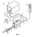
- Fig. 1 is a pictorial view of a welding system in accordance with one aspect of the present invention.
- Fig. 2 is a perspective view of a push-pull-type MIG welding gun for use with the welding system illustrated in Fig. 1.
- Fig. 3 is a perspective view of a standard MIG welding gun for use with the welding system illustrated in Fig. 1.
- Fig. 4 is a perspective view of a spool-type MIG welding gun for use with the welding system illustrated in Fig. 1.
- Fig. 5 is a flow chart setting forth the steps of a gun detection algorithm in accordance with the present invention.
-
- The present invention will be described with respect to a gun detection and parameter setting process that automatically determines the type of welding gun connected to a wire feeder of a welding system. One skilled in the art, however, will appreciate that the present invention may equivalently be used for the detection of other welding components connected to a wire feeder or other apparatus of a welding system. Further, the present invention is also applicable for other high power output systems such as plasma cutting systems and induction heating systems.
- Referring to Fig. 1, a welding-
type system 10 is show incorporating the present invention.System 10 includes aportable power source 12, which can be an AC or a DC welding power supply operable in either a constant current (CC) or constant voltage (CV) mode. Thepower source 12 has awork cable 14 andclamp 16 designed to hold aworkpiece 18 forwelding. Power source 12 is also connected to awire feeder 20 via an input power cord orcable 21. Cable 21 is designed to translate power from thepower source 12 or other power supply to the wire feeder. Also connected between thepower source 12 and thewire feeder 20 is aweld cable 22. Thewire feeder 20 also includes a welding torch orgun 24 and avoltage sensing lead 25 withclip 26 configured to provide voltage at the weld feedback to the wire feeder and/or power source. Ashielding gas cylinder 28 is also connected to thewire feeder 20 to provide shielding gas throughhose 29 for the welding process. Alternately, thewire feeder 20 may be disposed in thepower source 12 to provide an integrated MIG welder. - The
wire feeder 20 includes awire drive assembly 30 that includes a spool of welding wire (not shown) that is supplied to the weld under control of acontroller 32 that is connected to thepower source 12 throughcord 22. The controller is governed by a microprocessor capable of being programmed to operate according to certain algorithms and/or programs. User selections or inputs received by the controller from a display andcontrol panel 34 and an internally programmed algorithm causewelding system 10 to operate according to the user selections. For example, the wire feeder includes an output terminal or receptacle 36 that is designed to receive apin connector 37 designed to engage the output terminal. Thepin connector 37 is connected togun 24 viacable 38. - When the
welding torch 24 is positioned proximate toworkpiece 18, welding wire is fed into contact with theworkpiece 18. Once triggered, an electrical current and voltage are generated to cause the welding wire to be heated and melt. As a result, an electrical arc is established which causes the welding wire to continue to melt as well as transfer the melted welding wire to theworkpiece 18 where the welding wire fuses and cools with theworkpiece 18. Because the electrical energy supplied to the welding system is typically greater than that required to melt the welding wire, most of the remaining energy is in the form of heat which is transferred to the surface of theworkpiece 18 resulting in theworkpiece 18 also melting and improved bonding between the melted welding wire and theworkpiece 18. As thewelding torch 24 is translated across theworkpiece 18, melted welding wire is continuously transferred to theworkpiece 18. - The power source is designed to operate in either a CC or CV mode. The wire feeder is also designed to introduce flux cored, solid steel, or stainless steel welding wire to a weld. One skilled in the art would appreciate that the present invention is equivalently applicable with other welding systems having different operating specifications and other consumable types.
- Referring now to Fig. 2, welding
gun 24 is perspectively illustrated. Weldinggun 24 is an exemplary push-pull type of welding gun that includes an internal motor and driveassembly 40 designed to pull welding wire from the wire feeder or other welding wire source. As will be described in greater detail below, the illustrated push-pull welding gun is an example of only one type of welding gun or torch that may be applicable with the present invention. That is, other types of welding guns are contemplated for use with the welding system illustrated in Fig. 1 in accordance with the present invention. - As indicated previously, welding
gun 24 is a push-pull type of welding component that utilizes an internal motor and driveassembly 40 to pull wire from a wire feeder or other source of welding wire. The welding gun may be air cooled or liquid cooled. As will be further described, weldinggun 24 is typically connected to the wire feeder with a 10-pin connector. Weldinggun 24 is defined by agun body 42 that is connected, or integrally formed, withbarrel 44. At one end ofbarrel 44 is acontact tip 46 that, as described above, is used to initiate a welding arc.Tip 46 is centrally disposed withinnozzle 48 which is connected to anozzle adaptor 50. The nozzle and nozzle adaptor may be rotated so as to adjust the position of the tip relative to the nozzle. That is, the tip may be repositioned to extend beyond the end of the nozzle or, alternatively, be repositioned to extend entirely within the nozzle. Weldinggun 24 also includes a handle 47 having atrigger mechanism 48 operationally mounted thereto. As discussed above, when the trigger is depressed, an electrical current and voltage are generated to cause the welding wire to be heated and melt. As a result, an electrical arc is established which causes the welding wire to continue to melt as well as transfer the melted welding wire to the workpiece. - Referring now to Fig. 3, another type of
welding gun 51 that may be connected to the wire feeder illustrated in Fig. 1 is shown. Weldinggun 51 is a conventional MIG welding gun that is used to initiate and maintain welding of a consumable to a workpiece. Weldinggun 51 is also defined by agun body 52 having ahandle 54 andtrigger mechanism 56. In contrast to the push-pull gun 24 illustrated in Fig. 2, weldinggun 51 typically includes a 4-pin connector. Similar to weldinggun 24, weldinggun 51 includes abarrel 58 that is connected to awelding nozzle 60 having a tip disposed therein 62. Unlike the push-pull type of welding gun illustrated in Fig. 2, weldinggun 50 does not include a separate motor and drive assembly to pull welding wire from the wire source. In this regard, weldinggun 51 is designed to simply receive the welding wire being pushed by the drive and motor assembly within the wire feeder and deliver that welding wire to the weld. - Referring now to Fig. 4, another type of welding gun is shown. Welding
gun 64 is typically considered a spool-type gun that includes an independent source of welding wire housed within aninternal spool 66. Wire is introduced to the weld from theinternal spool 66 by a motor and driveassembly 68 disposed within thegun handle 70. Disposed onhandle 70 is a triggeringmechanism 72 that, similar to the previously described welding guns, commences the welding process when depressed by a user. Similar to the welding guns of Figs. 2 and 3, weldinggun 64 includes abarrel 74 that is connected to anozzle 76 having acontact tip 78 disposed therein. Additionally, similar to the push-pull welding gun of Fig. 2, weldinggun 64 typically includes a 10-pin connector for connection to an output terminal of a wire feeder. - Referring now to Fig. 5, the steps of a control algorithm for automatically determining the type of welding gun connected to a wire feeder and setting operating parameters of the wire feeder based on the determined gun type is illustrated. For purposes of illustration and not limitation, the control algorithm will be described with respect to delineation between a standard MIG gun such as that described with respect to Fig. 3, a spool-type gun such as that described with respect to Fig. 4, and a push-pull-type gun such as that described with respect to Fig. 2. However, the present invention is equivalently applicable with the detection of other types of welding guns or other welding components.
-
Process 80 begins at 82 with the connection of a welding gun or other component to be automatically detected to the wire feeder of a welding system. When the user depresses the trigger on the handle of the welding gun or otherwise provides a signal indicative of commencement of the welding process, e.g. connection of a serial link between the welding gun and the wire feeder, an input is received at 84. From theinput 84,algorithm 80 determines at 86 whether the input was received across a 4-pin or a 10-pin connector. If the input was received across a 4-pin connector controller executing algorithm 80 determines that the input was received across a 10-pin connector - In one exemplary embodiment, the controller compares the measured impedance to a look-up table of values to determine if the input was received from a spool gun. In a further embodiment, the look-up table may also include values delineating between the type of spool guns that may be connectable to the wire feeder. If, based on a comparison between the measured impedance and values contained in one or more look-up tables, the impedance of the feed motor in the welding gun corresponds to that of a
spool gun 34, 36 then the motor in the gun is enabled in a constant speed mode at 98. Alternately, characteristics of an electrical circuit or digital signature in the gun may be matched with values in a look-up table to determine the type of gun connected. In this regard, it is determined that a spool gun has been connected to the wire feeder and, accordingly, operating parameters of the spool gun are automatically set based on the determination made at 94. In contrast, if the impedance of the feed motor does not equal that of a spool-type gun algorithm 80 concludes at 106. - One skilled in the art will readily appreciate that the present invention may also be implemented to delineate between types of standard MIG guns, spool-type guns, and push-pull-type guns. That is, while Fig. 5 has been described with respect to delineating between a push-pull gun, a standard MIG gun, and a spool-type gun,
process 80 may also be implemented to differentiate between various types of push-pull guns, spool-type guns, or conventional MIG welding guns. For example, onceprocess 80 concludes that a push-pull-type gun is connected to the wire feeder, a further determination may be made to determine whether a certain type of push-pull-type gun is connected. In this further embodiment, the impedance or some other characteristic of the motor in the push-pull gun may be examined and compared to a set of values in a look-up table to determine the type of push-pull welding gun. Based on the type of push-pull welding gun determined, the operating parameters of the motor in the gun as well as the motor in the wire feeder may be set to a value more tailored to the type of push-pull gun connected to the wire feeder. Further, the look-up table is preferably stored in volatile memory that may be updated as new gun types and models are developed. - As one skilled in the art will fully appreciate, the heretofore description of welding devices not only includes welders, but also includes any system that requires high power outputs, such as heating and cutting systems. Therefore, the present invention is equivalently applicable with any device requiring high power output, including welders, plasma cutters, induction heaters, and the like. Reference to welding power, welding-type power, or welders generally, includes welding, cutting, or heating power. Description of a welding apparatus illustrates just one embodiment in which the present invention may be implemented. The present invention is equivalently applicable with many high power systems, such as cutting and induction heating systems, or any similar systems.
- Therefore, in accordance with one embodiment of the present invention, a wire feeder is disclosed and includes an output connectable to a gun assembly. The wire feeder further includes a controller configured to automatically determine gun assembly type when the gun assembly is connected to the output.
- In accordance with another embodiment of the present invention, a controller for a welding-type system is configured to detect an impedance of a motor assembly designed to deliver welding wire to a weld. The controller is further configured to determine, from the impedance, a type of load placed on the motor assembly and, based on the type of load, automatically set an output mode of the motor assembly.
- According to yet another embodiment of the present invention, a method of controlling operation of a wire feeder includes the step of determining a configuration of pins in a connector connecting a welding gun assembly to a wire feeder. From the configuration of pins, an output mode of a motor assembly in the wire feeder is automatically set.
- In accordance with yet a further embodiment of the present invention, a wire feeder includes means for determining a type of welding gun connected to deliver welding wire to a weld and means for automatically setting an output mode of a motor drive assembly based on the type of welding gun.
- The present invention has been described in terms of the preferred embodiment, and it is recognized that equivalents, alternatives, and modifications, aside from those expressly stated, are possible and within the scope of the appending claims.
- The claims refer to examples of preferred embodiments of the invention. However, the invention also refers to the use of any single feature and subcombination of features which are disclosed in the claims, description and/or the drawings.
Claims (12)
- A wire feeder comprising:an output connectable to a gun assembly; anda controller configured to automatically determine a type of gun assembly connected to the output.
- The wire feeder of claim 1 further comprising a motor assembly configured to deliver a consumable electrode to a weld when the gun assembly is activated.
- The wire feeder of claim 2 wherein the controller is further configured to determine gun assembly type based on an impedance of a motor assembly in the gun when the gun assembly is first activated.
- The wire feeder of claim 3 wherein the controller is further configured to determine gun assembly type when a trigger of the gun assembly is depressed.
- The wire feeder of claim 3 wherein the controller is further configured to determine gun assembly type when a serial communication link is established with a power source or wire feeder.
- The wire feeder of claim 3 wherein the controller is further configured to compare the impedance to a look-up table of impedance values to determine gun assembly type.
- The wire feeder of claim 2 wherein the motor assembly is further configured to deliver a consumable electrode to the weld at a constant speed if a four-pin connector is connected to the output.
- The wire feeder of claim 7 wherein the motor assembly is further configured to deliver a consumable electrode to the weld at a constant torque if a ten-pin connector of the gun assembly is connected to the output.
- The wire feeder of claim 8 wherein the controller is further configured to cause a motor in the gun assembly to deliver a consumable electrode to a weld at a constant speed if a ten-pin connector of the gun assembly is connected to the output.
- The wire feeder of claim 1 wherein the output is further configured to receive a connector of a MIG welding gun, a spool gun, or a push-pull welding gun.
- The controller of claim 1 configured to:detect an impedance of a motor assembly designed to deliver welding wire to a weld;from the impedance, determine a type of load placed on the motor assembly; andbased on the type of load, automatically set an output mode of the motor assembly.
- The controller of claim 11 wherein the output mode includes one of constant speed mode and constant torque mode with at least one feedback path to the motor assembly.
Applications Claiming Priority (2)
| Application Number | Priority Date | Filing Date | Title |
|---|---|---|---|
| US605450 | 1984-04-30 | ||
| US10/605,450 US6855914B1 (en) | 2003-09-30 | 2003-09-30 | Method and apparatus to automatically determine type of gun connected to a wire feeder |
Publications (3)
| Publication Number | Publication Date |
|---|---|
| EP1522370A2 true EP1522370A2 (en) | 2005-04-13 |
| EP1522370A3 EP1522370A3 (en) | 2006-09-20 |
| EP1522370B1 EP1522370B1 (en) | 2011-10-19 |
Family
ID=34115678
Family Applications (1)
| Application Number | Title | Priority Date | Filing Date |
|---|---|---|---|
| EP04019916A Expired - Fee Related EP1522370B1 (en) | 2003-09-30 | 2004-08-23 | Method and apparatus to automatically determine a type of gun connected to a wire feeder |
Country Status (5)
| Country | Link |
|---|---|
| US (2) | US6855914B1 (en) |
| EP (1) | EP1522370B1 (en) |
| AT (1) | AT500389A3 (en) |
| CA (1) | CA2479473C (en) |
| MX (1) | MXPA04009552A (en) |
Families Citing this family (43)
| Publication number | Priority date | Publication date | Assignee | Title |
|---|---|---|---|---|
| US6855914B1 (en) * | 2003-09-30 | 2005-02-15 | Illinois Tool Works Inc. | Method and apparatus to automatically determine type of gun connected to a wire feeder |
| US7208699B2 (en) * | 2005-02-03 | 2007-04-24 | Illinois Tool Works Inc. | Spool gun having unitary shielding gas and weld power connector |
| US20070039935A1 (en) * | 2005-08-17 | 2007-02-22 | Lincoln Global, Inc. | Contactor for welding wire feeder |
| US7624908B2 (en) | 2005-08-17 | 2009-12-01 | Lincoln Global, Inc. | Welding wire feeder and connection apparatus |
| US8431862B2 (en) | 2005-08-25 | 2013-04-30 | Lincoln Global, Inc. | Torch for electric arc welding system |
| US10144080B2 (en) | 2005-08-25 | 2018-12-04 | Lincoln Global, Inc. | Torch for electric arc welding or plasma cutting system |
| US8680433B2 (en) * | 2006-05-19 | 2014-03-25 | Illinois Tool Works Inc. | Method and apparatus for hand held and robotic welder |
| US20080156783A1 (en) * | 2006-12-29 | 2008-07-03 | Vanden Heuvel Michael L | Portable multi-wire feeder |
| US8026456B2 (en) * | 2007-02-20 | 2011-09-27 | Illinois Tool Works Inc. | TIG welding system and method |
| US8937265B2 (en) | 2007-02-27 | 2015-01-20 | Illinois Tool Works, Inc. | Welding-type system having a wire feeder system having integrated power source controls and a welding-type power source that is free power parameter selection interfaces |
| EP2131988A2 (en) * | 2007-02-27 | 2009-12-16 | Illinois Tool Works Inc. | Structural welding system |
| TWI430845B (en) * | 2007-03-16 | 2014-03-21 | Sulzer Metco Ag | A device and method for the management of data |
| US9399263B2 (en) | 2007-08-31 | 2016-07-26 | Hobart Brothers Company | Portable battery powered welder |
| US20090212027A1 (en) * | 2008-02-21 | 2009-08-27 | Hypertherm, Inc. | Binary Signal Detection |
| US8426773B2 (en) | 2008-02-27 | 2013-04-23 | Illinois Tool Works Inc. | Dual power pin connector assembly for a MIG welding machine |
| US9156104B2 (en) | 2008-08-29 | 2015-10-13 | Illinois Tool Works Inc. | Portable welding wearable wire feed and control system and method |
| US8476555B2 (en) | 2008-08-29 | 2013-07-02 | Illinois Tool Works Inc. | Portable welding wire feed system and method |
| US8803033B2 (en) | 2008-10-22 | 2014-08-12 | Lincoln Global, Inc. | Semi-automatic brazing device |
| US9114483B2 (en) * | 2009-11-02 | 2015-08-25 | Lincoln Global, Inc. | Drive roll assembly |
| US8445816B2 (en) * | 2009-11-13 | 2013-05-21 | Lincoln Global, Inc. | Modular process list for welding power supply |
| US9676050B2 (en) * | 2009-11-17 | 2017-06-13 | Illinois Tool Works Inc. | Welding system with lockout mechanism |
| US9545687B2 (en) | 2010-12-17 | 2017-01-17 | Hobart Brothers Company | Spool gun adapter |
| US20120241431A1 (en) * | 2011-03-25 | 2012-09-27 | Hobart Brothers Company | Welding arc powered spool gun |
| EP2589454B1 (en) | 2011-11-04 | 2016-03-30 | Ewm Ag | Control unit for a welding device, welding torch with an interface, and welding apparatus with such components |
| US20130119032A1 (en) * | 2011-11-11 | 2013-05-16 | Lincoln Global, Inc. | System and method for welding materials of different conductivity |
| US10213861B2 (en) * | 2013-03-11 | 2019-02-26 | Illinois Tool Works Inc. | Automated system for machine set-up of welding power sources and welding systems |
| CN103192391A (en) * | 2013-04-08 | 2013-07-10 | 苏州工业园区职业技术学院 | Five-axis full-automatic tin soldering robot servo control system |
| US9545684B2 (en) * | 2013-05-03 | 2017-01-17 | Illinois Tools Works Inc. | System and method for automated control of welding systems including a spool gun |
| CN103264392B (en) * | 2013-05-17 | 2016-01-20 | 苏州工业园区职业技术学院 | A kind of four-degree-of-freedom middling speed soldering robot serve control system |
| CN103223672A (en) * | 2013-05-17 | 2013-07-31 | 苏州工业园区职业技术学院 | Servo control system of four-axis full-automatic tin soldering robot |
| CN103302670A (en) * | 2013-05-17 | 2013-09-18 | 苏州工业园区职业技术学院 | Servo control system for four-axis intermediate speed full-automatic soldering robot |
| CN103240741A (en) * | 2013-05-17 | 2013-08-14 | 苏州工业园区职业技术学院 | Four-freedom-degree high-speed soldering robot servo control system |
| USD752666S1 (en) * | 2014-09-04 | 2016-03-29 | Illinois Tool Works Inc. | Wire feeder |
| US10373517B2 (en) * | 2015-08-12 | 2019-08-06 | Illinois Tool Works Inc. | Simulation stick welding electrode holder systems and methods |
| US10593230B2 (en) * | 2015-08-12 | 2020-03-17 | Illinois Tool Works Inc. | Stick welding electrode holder systems and methods |
| US10657839B2 (en) * | 2015-08-12 | 2020-05-19 | Illinois Tool Works Inc. | Stick welding electrode holders with real-time feedback features |
| US10343230B2 (en) | 2016-03-31 | 2019-07-09 | Illinois Tool Works Inc. | Welding-type systems and user interfaces having a color display for displaying physical setup instructions |
| MX2019000458A (en) | 2016-07-18 | 2019-04-22 | Victor Equipment Co | Plasma device consumable part change detection. |
| CN106111387A (en) * | 2016-08-04 | 2016-11-16 | 苏州优浦精密铸造有限公司 | The spray gun torch that a kind of aluminium ingot is special |
| US10987749B2 (en) * | 2017-01-04 | 2021-04-27 | Illinois Tool Works Inc. | Methods and systems for indicating a schedule in a welding-type torch |
| US11213907B2 (en) * | 2017-01-04 | 2022-01-04 | Illinois Tool Works Inc. | Methods and systems for selecting welding schedules in a welding-type torch |
| EP3366403A1 (en) * | 2017-02-10 | 2018-08-29 | Lincoln Global, Inc. | Welding system with shielding gas control |
| US10571150B2 (en) | 2017-05-16 | 2020-02-25 | Emerson Electric Co. | HVAC control assemblies, and corresponding methods of determining equipment wiring harness connections |
Citations (3)
| Publication number | Priority date | Publication date | Assignee | Title |
|---|---|---|---|---|
| DE4312224C1 (en) | 1993-04-14 | 1994-06-16 | Schuessler Technik Bernd Schue | Appts. for feeding solder wire in soldering installation - with wire deflection measured within its bending region resulting from an angle in the wire feed direction |
| US5834733A (en) | 1996-01-22 | 1998-11-10 | Matsushita Electric Industrial Co., Ltd. | ARC welding machine |
| US20040011776A1 (en) | 2001-07-30 | 2004-01-22 | Yasushi Mukai | Welding wire feeder |
Family Cites Families (8)
| Publication number | Priority date | Publication date | Assignee | Title |
|---|---|---|---|---|
| JPS5736372Y2 (en) * | 1978-09-21 | 1982-08-11 | ||
| US5208436A (en) * | 1991-04-12 | 1993-05-04 | The Lincoln Electric Company | Plasma torch with identification circuit |
| FR2717724B1 (en) * | 1994-03-24 | 1996-04-26 | Snecma | Automatic welding installation. |
| US6091048A (en) * | 1997-05-16 | 2000-07-18 | Illinois Tool Works Inc. | Welding machine with automatic parameter setting |
| US6066835A (en) * | 1998-09-04 | 2000-05-23 | S M C I, Inc. | Welding lead assembly |
| US6627849B2 (en) * | 2001-05-11 | 2003-09-30 | Illinois Tool Works Inc. | Automatic detection of robot type |
| US6563087B1 (en) * | 2001-11-14 | 2003-05-13 | Hakko Corporation | Automated soldering system |
| US6855914B1 (en) * | 2003-09-30 | 2005-02-15 | Illinois Tool Works Inc. | Method and apparatus to automatically determine type of gun connected to a wire feeder |
-
2003
- 2003-09-30 US US10/605,450 patent/US6855914B1/en not_active Expired - Lifetime
-
2004
- 2004-08-23 EP EP04019916A patent/EP1522370B1/en not_active Expired - Fee Related
- 2004-08-30 CA CA002479473A patent/CA2479473C/en not_active Expired - Fee Related
- 2004-09-27 AT AT0160704A patent/AT500389A3/en not_active Application Discontinuation
- 2004-09-30 MX MXPA04009552A patent/MXPA04009552A/en active IP Right Grant
- 2004-11-16 US US10/904,564 patent/US7329834B2/en active Active
Patent Citations (3)
| Publication number | Priority date | Publication date | Assignee | Title |
|---|---|---|---|---|
| DE4312224C1 (en) | 1993-04-14 | 1994-06-16 | Schuessler Technik Bernd Schue | Appts. for feeding solder wire in soldering installation - with wire deflection measured within its bending region resulting from an angle in the wire feed direction |
| US5834733A (en) | 1996-01-22 | 1998-11-10 | Matsushita Electric Industrial Co., Ltd. | ARC welding machine |
| US20040011776A1 (en) | 2001-07-30 | 2004-01-22 | Yasushi Mukai | Welding wire feeder |
Also Published As
| Publication number | Publication date |
|---|---|
| AT500389A2 (en) | 2005-12-15 |
| MXPA04009552A (en) | 2005-05-17 |
| EP1522370B1 (en) | 2011-10-19 |
| AT500389A3 (en) | 2006-08-15 |
| US6855914B1 (en) | 2005-02-15 |
| EP1522370A3 (en) | 2006-09-20 |
| US7329834B2 (en) | 2008-02-12 |
| CA2479473C (en) | 2007-07-17 |
| CA2479473A1 (en) | 2005-03-30 |
| US20050067396A1 (en) | 2005-03-31 |
Similar Documents
| Publication | Publication Date | Title |
|---|---|---|
| EP1522370B1 (en) | Method and apparatus to automatically determine a type of gun connected to a wire feeder | |
| CN110621434B (en) | System and method for preheating welding wire | |
| US10252367B2 (en) | Method and system of welding with auto-determined startup parameters | |
| US6204476B1 (en) | Welding power supply for pulsed spray welding | |
| EP3634679B1 (en) | System, and method to control welding electrode preheating | |
| US11911859B2 (en) | Systems, methods, and apparatus to provide preheat voltage feedback loss protection | |
| US7091449B2 (en) | Voltage regulated MIG welding using a constant current power source | |
| US7800018B2 (en) | Method and system of welding with adaptive crater fill control | |
| Conrardy | Gas metal arc welding |
Legal Events
| Date | Code | Title | Description |
|---|---|---|---|
| PUAI | Public reference made under article 153(3) epc to a published international application that has entered the european phase |
Free format text: ORIGINAL CODE: 0009012 |
|
| 17P | Request for examination filed |
Effective date: 20040823 |
|
| AK | Designated contracting states |
Kind code of ref document: A2 Designated state(s): AT BE BG CH CY CZ DE DK EE ES FI FR GB GR HU IE IT LI LU MC NL PL PT RO SE SI SK TR |
|
| AX | Request for extension of the european patent |
Extension state: AL HR LT LV MK |
|
| PUAL | Search report despatched |
Free format text: ORIGINAL CODE: 0009013 |
|
| AK | Designated contracting states |
Kind code of ref document: A3 Designated state(s): AT BE BG CH CY CZ DE DK EE ES FI FR GB GR HU IE IT LI LU MC NL PL PT RO SE SI SK TR |
|
| AX | Request for extension of the european patent |
Extension state: AL HR LT LV MK |
|
| 17Q | First examination report despatched |
Effective date: 20061206 |
|
| AKX | Designation fees paid |
Designated state(s): DE FR GB IT |
|
| GRAP | Despatch of communication of intention to grant a patent |
Free format text: ORIGINAL CODE: EPIDOSNIGR1 |
|
| GRAS | Grant fee paid |
Free format text: ORIGINAL CODE: EPIDOSNIGR3 |
|
| GRAA | (expected) grant |
Free format text: ORIGINAL CODE: 0009210 |
|
| AK | Designated contracting states |
Kind code of ref document: B1 Designated state(s): DE FR GB IT |
|
| REG | Reference to a national code |
Ref country code: GB Ref legal event code: FG4D |
|
| REG | Reference to a national code |
Ref country code: DE Ref legal event code: R096 Ref document number: 602004034885 Country of ref document: DE Effective date: 20111222 |
|
| PLBE | No opposition filed within time limit |
Free format text: ORIGINAL CODE: 0009261 |
|
| STAA | Information on the status of an ep patent application or granted ep patent |
Free format text: STATUS: NO OPPOSITION FILED WITHIN TIME LIMIT |
|
| PG25 | Lapsed in a contracting state [announced via postgrant information from national office to epo] |
Ref country code: IT Free format text: LAPSE BECAUSE OF FAILURE TO SUBMIT A TRANSLATION OF THE DESCRIPTION OR TO PAY THE FEE WITHIN THE PRESCRIBED TIME-LIMIT Effective date: 20111019 |
|
| 26N | No opposition filed |
Effective date: 20120720 |
|
| REG | Reference to a national code |
Ref country code: DE Ref legal event code: R097 Ref document number: 602004034885 Country of ref document: DE Effective date: 20120720 |
|
| GBPC | Gb: european patent ceased through non-payment of renewal fee |
Effective date: 20120823 |
|
| REG | Reference to a national code |
Ref country code: FR Ref legal event code: ST Effective date: 20130430 |
|
| PG25 | Lapsed in a contracting state [announced via postgrant information from national office to epo] |
Ref country code: GB Free format text: LAPSE BECAUSE OF NON-PAYMENT OF DUE FEES Effective date: 20120823 Ref country code: DE Free format text: LAPSE BECAUSE OF NON-PAYMENT OF DUE FEES Effective date: 20130301 |
|
| PG25 | Lapsed in a contracting state [announced via postgrant information from national office to epo] |
Ref country code: FR Free format text: LAPSE BECAUSE OF NON-PAYMENT OF DUE FEES Effective date: 20120831 |
|
| REG | Reference to a national code |
Ref country code: DE Ref legal event code: R119 Ref document number: 602004034885 Country of ref document: DE Effective date: 20130301 |