EP1522267B1 - External fixation elements - Google Patents
External fixation elements Download PDFInfo
- Publication number
- EP1522267B1 EP1522267B1 EP04405626A EP04405626A EP1522267B1 EP 1522267 B1 EP1522267 B1 EP 1522267B1 EP 04405626 A EP04405626 A EP 04405626A EP 04405626 A EP04405626 A EP 04405626A EP 1522267 B1 EP1522267 B1 EP 1522267B1
- Authority
- EP
- European Patent Office
- Prior art keywords
- rod
- sheath
- external fixation
- clamp
- pin
- Prior art date
- Legal status (The legal status is an assumption and is not a legal conclusion. Google has not performed a legal analysis and makes no representation as to the accuracy of the status listed.)
- Expired - Lifetime
Links
- 239000000463 material Substances 0.000 claims description 13
- 239000011347 resin Substances 0.000 claims description 8
- 229920005989 resin Polymers 0.000 claims description 8
- 229920000049 Carbon (fiber) Polymers 0.000 claims description 7
- 239000004917 carbon fiber Substances 0.000 claims description 7
- RTAQQCXQSZGOHL-UHFFFAOYSA-N Titanium Chemical compound [Ti] RTAQQCXQSZGOHL-UHFFFAOYSA-N 0.000 claims description 6
- XAGFODPZIPBFFR-UHFFFAOYSA-N aluminium Chemical compound [Al] XAGFODPZIPBFFR-UHFFFAOYSA-N 0.000 claims description 6
- 229910052782 aluminium Inorganic materials 0.000 claims description 6
- VNWKTOKETHGBQD-UHFFFAOYSA-N methane Chemical compound C VNWKTOKETHGBQD-UHFFFAOYSA-N 0.000 claims description 6
- 229910052719 titanium Inorganic materials 0.000 claims description 6
- 239000010936 titanium Substances 0.000 claims description 6
- 238000000034 method Methods 0.000 claims description 4
- 230000008569 process Effects 0.000 claims description 3
- 238000009745 resin transfer moulding Methods 0.000 claims description 3
- 239000003302 ferromagnetic material Substances 0.000 claims description 2
- 238000002595 magnetic resonance imaging Methods 0.000 description 14
- 239000011162 core material Substances 0.000 description 12
- OKTJSMMVPCPJKN-UHFFFAOYSA-N Carbon Chemical group [C] OKTJSMMVPCPJKN-UHFFFAOYSA-N 0.000 description 5
- 238000009413 insulation Methods 0.000 description 5
- 229920000508 Vectran Polymers 0.000 description 4
- 239000004979 Vectran Substances 0.000 description 4
- 238000005452 bending Methods 0.000 description 4
- 230000005294 ferromagnetic effect Effects 0.000 description 4
- 210000000988 bone and bone Anatomy 0.000 description 3
- 210000003414 extremity Anatomy 0.000 description 3
- 239000007943 implant Substances 0.000 description 3
- 230000005291 magnetic effect Effects 0.000 description 3
- 230000003068 static effect Effects 0.000 description 3
- 229920000271 Kevlar® Polymers 0.000 description 2
- 238000010438 heat treatment Methods 0.000 description 2
- 230000003993 interaction Effects 0.000 description 2
- 239000004761 kevlar Substances 0.000 description 2
- 239000000696 magnetic material Substances 0.000 description 2
- 230000007383 nerve stimulation Effects 0.000 description 2
- 208000010392 Bone Fractures Diseases 0.000 description 1
- 239000004698 Polyethylene Substances 0.000 description 1
- 238000010521 absorption reaction Methods 0.000 description 1
- 239000002885 antiferromagnetic material Substances 0.000 description 1
- 230000036760 body temperature Effects 0.000 description 1
- 239000000919 ceramic Substances 0.000 description 1
- 239000002131 composite material Substances 0.000 description 1
- 239000003814 drug Substances 0.000 description 1
- 239000000835 fiber Substances 0.000 description 1
- 230000006872 improvement Effects 0.000 description 1
- 239000011810 insulating material Substances 0.000 description 1
- 210000003141 lower extremity Anatomy 0.000 description 1
- 210000003205 muscle Anatomy 0.000 description 1
- 230000017074 necrotic cell death Effects 0.000 description 1
- 210000005036 nerve Anatomy 0.000 description 1
- 239000012811 non-conductive material Substances 0.000 description 1
- 230000000399 orthopedic effect Effects 0.000 description 1
- 210000004197 pelvis Anatomy 0.000 description 1
- 239000004033 plastic Substances 0.000 description 1
- 229920003023 plastic Polymers 0.000 description 1
- -1 polyethylene Polymers 0.000 description 1
- 229920000573 polyethylene Polymers 0.000 description 1
- 229910001220 stainless steel Inorganic materials 0.000 description 1
- 239000010935 stainless steel Substances 0.000 description 1
- 230000000638 stimulation Effects 0.000 description 1
- 210000001519 tissue Anatomy 0.000 description 1
Images
Classifications
-
- A—HUMAN NECESSITIES
- A61—MEDICAL OR VETERINARY SCIENCE; HYGIENE
- A61B—DIAGNOSIS; SURGERY; IDENTIFICATION
- A61B17/00—Surgical instruments, devices or methods
- A61B17/56—Surgical instruments or methods for treatment of bones or joints; Devices specially adapted therefor
- A61B17/58—Surgical instruments or methods for treatment of bones or joints; Devices specially adapted therefor for osteosynthesis, e.g. bone plates, screws or setting implements
- A61B17/60—Surgical instruments or methods for treatment of bones or joints; Devices specially adapted therefor for osteosynthesis, e.g. bone plates, screws or setting implements for external osteosynthesis, e.g. distractors, contractors
-
- A—HUMAN NECESSITIES
- A61—MEDICAL OR VETERINARY SCIENCE; HYGIENE
- A61B—DIAGNOSIS; SURGERY; IDENTIFICATION
- A61B17/00—Surgical instruments, devices or methods
- A61B17/56—Surgical instruments or methods for treatment of bones or joints; Devices specially adapted therefor
- A61B17/58—Surgical instruments or methods for treatment of bones or joints; Devices specially adapted therefor for osteosynthesis, e.g. bone plates, screws or setting implements
- A61B17/60—Surgical instruments or methods for treatment of bones or joints; Devices specially adapted therefor for osteosynthesis, e.g. bone plates, screws or setting implements for external osteosynthesis, e.g. distractors, contractors
- A61B17/64—Devices extending alongside the bones to be positioned
- A61B17/6466—Devices extending alongside the bones to be positioned with pin-clamps movable along a solid connecting rod
-
- A—HUMAN NECESSITIES
- A61—MEDICAL OR VETERINARY SCIENCE; HYGIENE
- A61B—DIAGNOSIS; SURGERY; IDENTIFICATION
- A61B17/00—Surgical instruments, devices or methods
- A61B17/56—Surgical instruments or methods for treatment of bones or joints; Devices specially adapted therefor
- A61B17/58—Surgical instruments or methods for treatment of bones or joints; Devices specially adapted therefor for osteosynthesis, e.g. bone plates, screws or setting implements
- A61B17/68—Internal fixation devices, including fasteners and spinal fixators, even if a part thereof projects from the skin
- A61B17/84—Fasteners therefor or fasteners being internal fixation devices
- A61B17/86—Pins or screws or threaded wires; nuts therefor
- A61B17/866—Material or manufacture
Definitions
- the invention relates to a clamp for an external fixation system according to the preamble of claim 1.
- Magnetic resonance imaging is a well known diagnostic tool in the field of medicine. It is equally known to surgeons that it may be dangerous for patients wearing metallic devices inside or outside their body to be examined with a MRI device (inside or outside the coil).
- US 2002/042619 discloses a headframe for use with a stereotactic system. It is mentioned in the last paragraph of the description of said document that the frame body and swivel arms need not to be made from aluminum. Instead, the frame body and swivel arms as well as other components of the headframe may be formed of a non-magnetic material such as plastic, ceramic, or other composite such that the headframe is compatible with MRI, CT, X-ray and magnetic stereotactic devices/procedures.
- Document CH 303453 discloses an external fixation system comprising a rod and two clamps, the clamps comprising on the inner side of the jaws an insulating material.
- Document EP 0 7171 968 discloses an external fixation system comprising a rod and clamps, the rod captured by and extending between the clamps and being made from a non-ferromagnetic material core surrounded by a non-electrically conductive sheath.
- the object of the invention is to provide external fixation elements, wherein a patient carrying such a structure can safely be examined within a MRI device.
- critical heat can be generated in such external fixation frames that can cause burns, necrosis or nerve stimulation in the tissue of the human body. Furthermore a torque may be generated resulting in a vibration or movement of the device.
- the field strength i.e. the highest strength of the static magnetic field of a MR system, is often between 1.5 Tesla and 3.0 Tesla, more often around 2.0 Tesla.
- elements according to the invention can also be used in association with very high-field-strength MR systems having a field strength of up to 8.0 Tesla.
- a clamp having the features mentioned in the preamble of claim 1, using two wedge elements is known from US-A-4, 757, 809 .
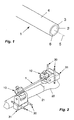
- Fig. 1 shows a schematic view of a rod 1 for use in an external fixation device.
- the core has received the reference numeral 2.
- a non-conductive sheath 3 encloses the core 2.
- the cylindrical surface 4 of the sheath may be smooth or comprise a grid of high spots.
- rod 1 is available with different diameters depending on its use in an external fixation device, e.g. as thicker rods 1 and thinner pins 31 as shown in Fig. 2 .
- the rod 1 according to the invention is to be used with further elements of an external fixation system or frame, e.g. clamps 10 and 31 as shown in Fig. 2.
- Fig. 2 shows a schematic view of the use of a external fixation system with a broken bone 20 using several fixation elements according to the invention.
- Pins 30 are drilled into the bone parts 21 and 22, respectively and held within clamp parts 31.
- the clamp parts 31 are mounted together with clamps 10.
- the two clamps 10 are connected via the rod 1 oriented mainly in parallel to the broken limb.
- the clamps 10 and 31 can be made of titanium. Such clamps 10 are then non-ferromagnetic but electrically conductive. However, the use of such conductive clamps 10 and 31 does not close the external fixation frame to a closed electrical loop, since the rods 1 are not conductive. Therefore the combination of the disclosed rods 1 from an anti-ferromagnetic material with clamps 10 and 31 and pins 30 are MRI-safe. There are almost no induced currents.
- the use of the non-conductive elements 1 disrupts the closed loop usually formed by rod 1, clamp parts 10 and 31, pin 30 and the human body, here represented through the bone parts 21 und 22.
- the use of non magnetic material for clamp 31 also disrupts the smaller loop formed by the two pins 30 together with one clamp part 31 and the bone.
- not conductive clamps 10 e.g. titanium clamp bodies covered at least on the inside with an insulation sheath 34, i.e. around the jaws 40 of the clamp.
- the insulation sheath 33 is also provided on the outside of the clamp.
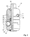
- a clamp 10 with an insulation sheath 34 and 33 is shown in Fig. 3 being a representation of the clamp 10, seen in section in the left and laterally in the right part of the drawing.
- the elements 32 constituting the core of the clamp 10 can be in carbon fiber or titanium, although the use of aluminum is preferred.
- clamp 10 The different constituting parts of clamp 10 are known to someone skilled in the art and are explained in US 6,080,153 .
- the insulation 34 as shown in Fig. 3 may function in a different was as explained below.
- the rod 1 comprises the core 2 and the sheath 3, the clamp's teeth 41 enter into the sheath 3.
- the teeth 41 can be made of the core material of the clamp 10 for use with said rod 1 are made of titanium or aluminum and are as such not ferromagnetic, however conductive.
- the teeth 41 of the jaws 40 have a length of e.g. 0,3 millimeter, wherein the sheath 3 has a radial thickness of e.g. 0,7 millimeter.
- the insulation sheath 41 may well extend also in the area of the jaws 40.
- Fig. 1 possible stresses on a rod are evaluated.
- One of the stresses a system may receive is a torsion exerted via two clamps 10, i.e. one end of the rod 1 is rotated around his main axle 5 while the opposite end of the rod 1 is held or rotated in the opposite direction. If the torque would now be increased until the system breaks, what will not happen to a surgeon using the usual tools, there are two possible scenarios. In one case it would be the sheath 3 which separates from the core 2 of the rod 1, wherein the teeth 41 of the jaws 40 or the inner surface of the jaws 40 are holding the sheath 3 fast. The second possibility resides in the fact that the teeth 21 of the jaws 20 of the clamp 10 are gliding along the circumference of the sheath 3.
- the rod 1 or pin 30 is designed in such a way that the clamp 10 will start to glide along the circumference of the sheath 3 before the surfaces between core 2 and sheath 3 are separating upon an growing torque. In such a way the rod 1 remains intact in the case that excessive torque stresses are exerted on said rod 1. The same apply in case of tensile forces acting along the longitudinal axle 5.
- the core 2 may be formed with a protrusion process.
- RTM resin transfer moulding
- the core 2 may be non-metallic or metallic, conductive or non-conductive. Its main function is to provide stiffness.
- the electrical resistivity of the rods 1 or pins 30 shall preferably be greater than 1 kOhm ⁇ cm.
- the torsional stiffness for rods with 5 mm diameter shall preferably be greater than 0.2 Nm2.
- the torsional strength for such rods shall preferably be greater than 2 Nm.
- the bending stiffness for such rods shall preferably be greater than 2.5 Nm2.
- the bending strength for such rods shall preferably be greater than 15 Nm.
- the torsional stiffness for rods with 8 mm diameter shall preferably be greater than 1.5 Nm2.
- the torsional strength for such rods shall preferably be greater than 11 Nm.
- the bending stiffness for such rods shall preferably be greater than 20 Nm2.
- the bending strength for such rods shall preferably be greater than 40 Nm.
- the rods 1 are especially MRI safe for the patient when used in any frame configuration for the upper & lower extremities and pelvis, and especially when used in conjunction with Hoffmann II clamps of applicant's MRI safe product line, wherein the following MRI field parameters apply:
- a device is considered MRI safe if there is:
- any orthopedic frame for external fixation build with the elements described in this application and according to the appended claims can be considered MRI safe irrespective of the position of the frame, i.e. the device can be used for the external fixation of any broken limb of the patient.
- the improvement to the MRI Safe invention relates also to the choice of material and the manner in which that material was applied to the carbon core.
- a higher modulus carbon fiber is used because the size of the carbon core must be reduced so that once the second material is applied to it, the resulting product has the same size as rods traditionally used by surgeons in external fixation systems.
- the reduced size, high modulus carbon core can be inserted into a sheath or sock of braided Vectran. Resin is "infused" through the braided Vectran material, a vacuum being used to pull the resin through the sock. There is an additional heating process step by which the resin is cured.
- the Vectran material, resin and carbon core are heated to about 160°C.
- the MRI Safe device according to the invention is gamma resistant, nonconductive, nonmagnetic, and radiolucent. If gamma resistance is not crucial Kevlar can be used as sheath material. Kevlar sheaths have shown to discolor over time, therefore indicating the age of the product. This may be undesirable.
- the thickness of the sheath is important because if it becomes too thick, then it becomes conductive, which is an undesirable property.
Landscapes
- Health & Medical Sciences (AREA)
- Orthopedic Medicine & Surgery (AREA)
- Life Sciences & Earth Sciences (AREA)
- Surgery (AREA)
- Biomedical Technology (AREA)
- Engineering & Computer Science (AREA)
- Nuclear Medicine, Radiotherapy & Molecular Imaging (AREA)
- Heart & Thoracic Surgery (AREA)
- Medical Informatics (AREA)
- Molecular Biology (AREA)
- Animal Behavior & Ethology (AREA)
- General Health & Medical Sciences (AREA)
- Public Health (AREA)
- Veterinary Medicine (AREA)
- Magnetic Resonance Imaging Apparatus (AREA)
Description
- The invention relates to a clamp for an external fixation system according to the preamble of
claim 1. - Magnetic resonance imaging (MRI) is a well known diagnostic tool in the field of medicine. It is equally known to surgeons that it may be dangerous for patients wearing metallic devices inside or outside their body to be examined with a MRI device (inside or outside the coil).
- It is known in the prior art, e.g. from
FR 2,703,580 -
US 2002/042619 discloses a headframe for use with a stereotactic system. It is mentioned in the last paragraph of the description of said document that the frame body and swivel arms need not to be made from aluminum. Instead, the frame body and swivel arms as well as other components of the headframe may be formed of a non-magnetic material such as plastic, ceramic, or other composite such that the headframe is compatible with MRI, CT, X-ray and magnetic stereotactic devices/procedures. - Document
CH 303453 - Document
EP 0 7171 968 - In the field of elements constituting an external fixation device or to be used with an external fixation device it is known to use e.g. rods in stainless steel. However, the use of such ferromagnetic rods does not allow MRI examinations. As alternative, rods in aluminum or in carbon fibers may be used. Rods made from the latter named materials are not ferromagnetic. However, within the field of external fixation, the combination of these elements, e.g. rods with clamps and pins, constitute in itself or together with the body of the patient a closed conductive loop.
- For MRI safety it is equally important not to interfere with the static field, the gradient field as well as the RF-field, therefore such external fixation elements cannot be used in MRI environments.
- In view of this prior art the object of the invention is to provide external fixation elements, wherein a patient carrying such a structure can safely be examined within a MRI device.
- During MRI scanning critical heat can be generated in such external fixation frames that can cause burns, necrosis or nerve stimulation in the tissue of the human body. Furthermore a torque may be generated resulting in a vibration or movement of the device.
- It is another object of the invention to provide external fixation elements with the least possible magnetic field interactions (i.e. deflection and/or torque), heating and nerve stimulation. It is a further object of the invention to limit artifacts in the generated MRI images due to the external fixation elements.
- The field strength, i.e. the highest strength of the static magnetic field of a MR system, is often between 1.5 Tesla and 3.0 Tesla, more often around 2.0 Tesla. However elements according to the invention can also be used in association with very high-field-strength MR systems having a field strength of up to 8.0 Tesla.
- A clamp having the features mentioned in the preamble of
claim 1, using two wedge elements is known fromUS-A-4, 757, 809 . - The above-mentioned objects are achieved for a clamp through the features of
claim 1. An external fixation system using such a clamp is claimed inclaim 4. - Further objects and advantages are achieved through the features of the subclaims and exemplary embodiments of the invention are disclosed in the following description in which:
- Fig. 1
- is a schematic view of a rod according to the invention for use in an external fixation device,
- Fig. 2
- is a view of several fixation elements according to the invention with a rod according to
Fig. 1 , and - Fig. 3
- is a representation of a clamp according to the invention, seen in section in the left and laterally in the right part of the drawing.
-
Fig. 1 shows a schematic view of arod 1 for use in an external fixation device. The core has received thereference numeral 2. A non-conductivesheath 3 encloses thecore 2. Thecylindrical surface 4 of the sheath may be smooth or comprise a grid of high spots. Preferablyrod 1 is available with different diameters depending on its use in an external fixation device, e.g. asthicker rods 1 andthinner pins 31 as shown inFig. 2 . - The
rod 1 according to the invention is to be used with further elements of an external fixation system or frame,e.g. clamps Fig. 2. Fig. 2 shows a schematic view of the use of a external fixation system with a broken bone 20 using several fixation elements according to the invention.Pins 30 are drilled into thebone parts clamp parts 31. Theclamp parts 31 are mounted together withclamps 10. The twoclamps 10 are connected via therod 1 oriented mainly in parallel to the broken limb. - The
clamps Such clamps 10 are then non-ferromagnetic but electrically conductive. However, the use of suchconductive clamps rods 1 are not conductive. Therefore the combination of the disclosedrods 1 from an anti-ferromagnetic material withclamps pins 30 are MRI-safe. There are almost no induced currents. The use of thenon-conductive elements 1 disrupts the closed loop usually formed byrod 1,clamp parts pin 30 and the human body, here represented through thebone parts 21 und 22. The use of non magnetic material forclamp 31 also disrupts the smaller loop formed by the twopins 30 together with oneclamp part 31 and the bone. - Beside the use of
conductive pins 30 it is in principle possible to use shielded or non conductive materials for saidpins 30. - On the other side, it is also possible to provide not
conductive clamps 10, e.g. titanium clamp bodies covered at least on the inside with aninsulation sheath 34, i.e. around thejaws 40 of the clamp. Theinsulation sheath 33 is also provided on the outside of the clamp. - Both solutions (clamp and/or rod) interrupt the electric loop of the frame and body of a patient and prevent serious induced currents.
- A
clamp 10 with aninsulation sheath Fig. 3 being a representation of theclamp 10, seen in section in the left and laterally in the right part of the drawing. Theelements 32 constituting the core of theclamp 10 can be in carbon fiber or titanium, although the use of aluminum is preferred. - The different constituting parts of
clamp 10 are known to someone skilled in the art and are explained inUS 6,080,153 . - In the case that the
clamps 10 have on the inner side of thejaws 40 someteeth 41 gripping the outer surface of thesheath 3 of therod 1, theinsulation 34 as shown inFig. 3 may function in a different was as explained below. Since therod 1 comprises thecore 2 and thesheath 3, the clamp'steeth 41 enter into thesheath 3. Theteeth 41 can be made of the core material of theclamp 10 for use with saidrod 1 are made of titanium or aluminum and are as such not ferromagnetic, however conductive. Theteeth 41 of thejaws 40 have a length of e.g. 0,3 millimeter, wherein thesheath 3 has a radial thickness of e.g. 0,7 millimeter. In this way it is ensured that the possiblyconductive rod core 2 do not come in contact with theconductive teeth 41. The same apply for teeth which would be used to hold thepin 30. However in other embodiments theinsulation sheath 41 may well extend also in the area of thejaws 40. - Referring to
Fig. 1 possible stresses on a rod are evaluated. One of the stresses a system may receive is a torsion exerted via twoclamps 10, i.e. one end of therod 1 is rotated around hismain axle 5 while the opposite end of therod 1 is held or rotated in the opposite direction. If the torque would now be increased until the system breaks, what will not happen to a surgeon using the usual tools, there are two possible scenarios. In one case it would be thesheath 3 which separates from thecore 2 of therod 1, wherein theteeth 41 of thejaws 40 or the inner surface of thejaws 40 are holding thesheath 3 fast. The second possibility resides in the fact that theteeth 21 of the jaws 20 of theclamp 10 are gliding along the circumference of thesheath 3. - According to a preferred embodiment the
rod 1 orpin 30 is designed in such a way that theclamp 10 will start to glide along the circumference of thesheath 3 before the surfaces betweencore 2 andsheath 3 are separating upon an growing torque. In such a way therod 1 remains intact in the case that excessive torque stresses are exerted on saidrod 1. The same apply in case of tensile forces acting along thelongitudinal axle 5. - The
core 2 may be formed with a protrusion process. Through resin transfer moulding (RTM) asheath 3 having a known resistivity is molded with thecore 2 allowing an interaction between a e.g.fiber carbon core 2 and thesheath 3 at theintermediate surface 6. - The
core 2 may be non-metallic or metallic, conductive or non-conductive. Its main function is to provide stiffness. - The electrical resistivity of the
rods 1 or pins 30 shall preferably be greater than 1 kOhm·cm. - The torsional stiffness for rods with 5 mm diameter shall preferably be greater than 0.2 Nm2. The torsional strength for such rods shall preferably be greater than 2 Nm. The bending stiffness for such rods shall preferably be greater than 2.5 Nm2. The bending strength for such rods shall preferably be greater than 15 Nm.
- The torsional stiffness for rods with 8 mm diameter shall preferably be greater than 1.5 Nm2. The torsional strength for such rods shall preferably be greater than 11 Nm. The bending stiffness for such rods shall preferably be greater than 20 Nm2. The bending strength for such rods shall preferably be greater than 40 Nm.
- The
rods 1 are especially MRI safe for the patient when used in any frame configuration for the upper & lower extremities and pelvis, and especially when used in conjunction with Hoffmann II clamps of applicant's MRI safe product line, wherein the following MRI field parameters apply: - Static field : max. 2 Tesla
- Time-varying field : max. 20 Tesla/sec.
- A device is considered MRI safe if there is:
- no risk of limb movements due to forces exhibited on the materials of the frame,
- no risk of nerve or muscle stimulation due to time-varying field,
- no risk of all body temperature rise greater than 1°C, due to induced current and temperature in the frame being a consequence of the RF field.
- It is important to note that any orthopedic frame for external fixation build with the elements described in this application and according to the appended claims can be considered MRI safe irrespective of the position of the frame, i.e. the device can be used for the external fixation of any broken limb of the patient.
- The improvement to the MRI Safe invention relates also to the choice of material and the manner in which that material was applied to the carbon core. A higher modulus carbon fiber is used because the size of the carbon core must be reduced so that once the second material is applied to it, the resulting product has the same size as rods traditionally used by surgeons in external fixation systems. The reduced size, high modulus carbon core can be inserted into a sheath or sock of braided Vectran. Resin is "infused" through the braided Vectran material, a vacuum being used to pull the resin through the sock. There is an additional heating process step by which the resin is cured. The Vectran material, resin and carbon core are heated to about 160°C.
- The MRI Safe device according to the invention is gamma resistant, nonconductive, nonmagnetic, and radiolucent. If gamma resistance is not crucial Kevlar can be used as sheath material. Kevlar sheaths have shown to discolor over time, therefore indicating the age of the product. This may be undesirable.
- With respect to Vectran as choice for the material of the non-conductive sheath part, the thickness of the sheath is important because if it becomes too thick, then it becomes conductive, which is an undesirable property.
Claims (7)
- A clamp (10) for an external fixation system, adapted to clamp a rod (1) or pin (30), comprising an anti-magnetic core body (32) and a non-conductive surface (33) forming a sheath part covering essentially the exterior surfaces of the core body (32), characterized in that the clamp (10) comprises jaws (40) having teeth (41) on the clamping surface provided to capture a rod (1) or pin (30), wherein the length of said teeth (41) is smaller than the thickness of the insulating sheath (3) of said rod (1) or pin (30).
- The clamp (10) according to claim 1, wherein the anti-magnetic core body (32) is made of titanium or aluminum or carbon fiber and/or the non-conductive sheath part (33) is made of resin material.
- The clamp (10) according to claim 2, wherein the anti-magnetic core part (32) is made of carbon fiber and the non-conductive sheath part (33) is made of co-extruded resin material within a resin transfer moulding (RTM) process.
- A MRI safe external fixation system comprising:at least two rod clamps (10) according to one of claims 1 to 3, andat least one rod (1) or pin (30) to be captured by and extending between said rod clamps (10), said rod or pin made from a non-ferromagnetic material core (2) surrounded by a non-electrically conductive sheath (3).
- The external fixation system according to claim 4, wherein the core (2) and sheath (3) of a rod (1) or pin (30) are holding together upon exertion of a torque around the main axle (5) of the rod (1) or pin (30) in such a way that any of said clamps (10) will start to glide along the circumference of the sheath (3) before the surfaces between core (2) and sheath (3) are separating upon an increasing torque.
- The external fixation system according to one of claims 4 or 5, wherein the anti-magnetic core body (2, 32) of any of said clamps (10) and any rod (2) or pin (30) is made of titanium or aluminum or carbon fiber and/or the non-conductive sheath part (3, 33) is made of resin material.
- The external fixation system according to claim 6, wherein the anti-magnetic core body (2, 32) is made of carbon fiber and the non-conductive sheath part (3, 33) is made of co-extruded resin material within a resin transfer moulding (RTM) process.
Priority Applications (1)
| Application Number | Priority Date | Filing Date | Title |
|---|---|---|---|
| EP04405626A EP1522267B1 (en) | 2003-10-06 | 2004-10-06 | External fixation elements |
Applications Claiming Priority (3)
| Application Number | Priority Date | Filing Date | Title |
|---|---|---|---|
| EP03405713A EP1522266A1 (en) | 2003-10-06 | 2003-10-06 | External fixation elements |
| EP03405713 | 2003-10-06 | ||
| EP04405626A EP1522267B1 (en) | 2003-10-06 | 2004-10-06 | External fixation elements |
Publications (2)
| Publication Number | Publication Date |
|---|---|
| EP1522267A1 EP1522267A1 (en) | 2005-04-13 |
| EP1522267B1 true EP1522267B1 (en) | 2009-01-14 |
Family
ID=34315342
Family Applications (1)
| Application Number | Title | Priority Date | Filing Date |
|---|---|---|---|
| EP04405626A Expired - Lifetime EP1522267B1 (en) | 2003-10-06 | 2004-10-06 | External fixation elements |
Country Status (1)
| Country | Link |
|---|---|
| EP (1) | EP1522267B1 (en) |
Families Citing this family (1)
| Publication number | Priority date | Publication date | Assignee | Title |
|---|---|---|---|---|
| DE502005005095D1 (en) | 2005-02-09 | 2008-10-02 | Stryker Trauma Sa | Insert for a clamping element, clamping element with such an insert and articulated connection formed therefrom |
Citations (1)
| Publication number | Priority date | Publication date | Assignee | Title |
|---|---|---|---|---|
| US4757809A (en) * | 1984-04-26 | 1988-07-19 | Orthotic Limited Partnership | Pin clamp |
Family Cites Families (8)
| Publication number | Priority date | Publication date | Assignee | Title |
|---|---|---|---|---|
| CH303453A (en) * | 1952-05-13 | 1954-11-30 | Raoul Dr Hoffmann | Fixer, especially for the treatment of bone fractures. |
| FR2338692A1 (en) * | 1976-01-23 | 1977-08-19 | Inst Nat Sante Rech Med | External fastener for reducing bone fractures - with articulated hoop connected to each group of transfixing pins |
| IT1143590B (en) * | 1977-07-22 | 1986-10-22 | Gentile Giulio | ARTICULATED SYSTEM FOR POSITIONING GRIPPING DEVICES ON BONE TISSUES FROM OUTSIDE |
| FR2703580B1 (en) | 1993-03-03 | 1997-10-17 | Gilles Robert | Cervical interbody fusion cage. |
| US5591164A (en) * | 1994-12-22 | 1997-01-07 | Zimmer, Inc. | External fixation apparatus and system |
| US6045553A (en) * | 1998-10-13 | 2000-04-04 | Pmt Corporation | Hybrid skull pins |
| US6770082B2 (en) | 2000-09-24 | 2004-08-03 | Medtronic, Inc. | Surgical headframe with soft contact pads for use with a stereotactic system |
| US7048735B2 (en) * | 2002-02-04 | 2006-05-23 | Smith & Nephew | External fixation system |
-
2004
- 2004-10-06 EP EP04405626A patent/EP1522267B1/en not_active Expired - Lifetime
Patent Citations (1)
| Publication number | Priority date | Publication date | Assignee | Title |
|---|---|---|---|---|
| US4757809A (en) * | 1984-04-26 | 1988-07-19 | Orthotic Limited Partnership | Pin clamp |
Also Published As
| Publication number | Publication date |
|---|---|
| EP1522267A1 (en) | 2005-04-13 |
Similar Documents
| Publication | Publication Date | Title |
|---|---|---|
| US7527626B2 (en) | External fixation element | |
| Tronnier et al. | Magnetic resonance imaging with implanted neurostimulators: an in vitro and in vivo study | |
| US6845259B2 (en) | MRI compatible guide wire | |
| US6379362B1 (en) | Insulated skull pins | |
| US7294785B2 (en) | Patient cable for medical measurements | |
| Luechinger et al. | Pacemaker reed switch behavior in 0.5, 1.5, and 3.0 Tesla magnetic resonance imaging units: are reed switches always closed in strong magnetic fields? | |
| Kim et al. | Safety issues and updates under MR environments | |
| Dempsey et al. | Thermal injuries associated with MRI | |
| Kugel et al. | Hazardous situation in the MR bore: induction in ECG leads causes fire | |
| US8945090B2 (en) | Implantable radiopaque marking | |
| Baker et al. | Reduction of magnetic resonance imaging-related heating in deep brain stimulation leads using a lead management device | |
| Zhang et al. | A method for simultaneous RF ablation and MRI | |
| US5663646A (en) | Head antenna for nuclear magnetic resonance examinations | |
| WO2010044019A1 (en) | Probe for an implantable medical device | |
| US20150338477A1 (en) | An active tracking system and method for mri | |
| US6896678B2 (en) | Ceramic-tipped skull pins | |
| Portnoy et al. | Cochlear implants as a contraindication to magnetic resonance imaging | |
| EP1522267A1 (en) | External fixation elements | |
| HK1071996A (en) | External fixation elements | |
| Mirvis et al. | Use of titanium wire in cervical spine fixation as a means to reduce MR artifacts. | |
| WO1998055016A1 (en) | Glass core guidewire compatible with magnetic resonance having reinforcing fibers | |
| JP2013505051A (en) | MRI system comprising a cardiac coil having an opening for a defibrillation electrode or a connector for a defibrillation cable | |
| Duffy Jr et al. | Tissue expanders and magnetic resonance imaging: the “hot” breast implant | |
| CN204440942U (en) | A kind of implanted electrode wire of MRI compatible and medicine equipment | |
| US9358386B2 (en) | Medical device for insertion into the human or animal body |
Legal Events
| Date | Code | Title | Description |
|---|---|---|---|
| PUAI | Public reference made under article 153(3) epc to a published international application that has entered the european phase |
Free format text: ORIGINAL CODE: 0009012 |
|
| AK | Designated contracting states |
Kind code of ref document: A1 Designated state(s): AT BE BG CH CY CZ DE DK EE ES FI FR GB GR HU IE IT LI LU MC NL PL PT RO SE SI SK TR |
|
| AX | Request for extension of the european patent |
Extension state: AL HR LT LV MK |
|
| REG | Reference to a national code |
Ref country code: HK Ref legal event code: DE Ref document number: 1071996 Country of ref document: HK |
|
| 17P | Request for examination filed |
Effective date: 20050614 |
|
| AKX | Designation fees paid |
Designated state(s): AT BE BG CH CY CZ DE DK EE ES FI FR GB GR HU IE IT LI LU MC NL PL PT RO SE SI SK TR |
|
| 17Q | First examination report despatched |
Effective date: 20070810 |
|
| GRAP | Despatch of communication of intention to grant a patent |
Free format text: ORIGINAL CODE: EPIDOSNIGR1 |
|
| GRAS | Grant fee paid |
Free format text: ORIGINAL CODE: EPIDOSNIGR3 |
|
| GRAA | (expected) grant |
Free format text: ORIGINAL CODE: 0009210 |
|
| AK | Designated contracting states |
Kind code of ref document: B1 Designated state(s): AT BE BG CH CY CZ DE DK EE ES FI FR GB GR HU IE IT LI LU MC NL PL PT RO SE SI SK TR |
|
| REG | Reference to a national code |
Ref country code: GB Ref legal event code: FG4D |
|
| REG | Reference to a national code |
Ref country code: CH Ref legal event code: EP |
|
| REG | Reference to a national code |
Ref country code: CH Ref legal event code: NV Representative=s name: ISLER & PEDRAZZINI AG |
|
| REG | Reference to a national code |
Ref country code: IE Ref legal event code: FG4D |
|
| REF | Corresponds to: |
Ref document number: 602004019030 Country of ref document: DE Date of ref document: 20090305 Kind code of ref document: P |
|
| REG | Reference to a national code |
Ref country code: ES Ref legal event code: FG2A Ref document number: 2320450 Country of ref document: ES Kind code of ref document: T3 |
|
| PG25 | Lapsed in a contracting state [announced via postgrant information from national office to epo] |
Ref country code: NL Free format text: LAPSE BECAUSE OF FAILURE TO SUBMIT A TRANSLATION OF THE DESCRIPTION OR TO PAY THE FEE WITHIN THE PRESCRIBED TIME-LIMIT Effective date: 20090114 |
|
| NLV1 | Nl: lapsed or annulled due to failure to fulfill the requirements of art. 29p and 29m of the patents act | ||
| PG25 | Lapsed in a contracting state [announced via postgrant information from national office to epo] |
Ref country code: FI Free format text: LAPSE BECAUSE OF FAILURE TO SUBMIT A TRANSLATION OF THE DESCRIPTION OR TO PAY THE FEE WITHIN THE PRESCRIBED TIME-LIMIT Effective date: 20090114 Ref country code: SI Free format text: LAPSE BECAUSE OF FAILURE TO SUBMIT A TRANSLATION OF THE DESCRIPTION OR TO PAY THE FEE WITHIN THE PRESCRIBED TIME-LIMIT Effective date: 20090114 |
|
| PG25 | Lapsed in a contracting state [announced via postgrant information from national office to epo] |
Ref country code: PL Free format text: LAPSE BECAUSE OF FAILURE TO SUBMIT A TRANSLATION OF THE DESCRIPTION OR TO PAY THE FEE WITHIN THE PRESCRIBED TIME-LIMIT Effective date: 20090114 Ref country code: AT Free format text: LAPSE BECAUSE OF FAILURE TO SUBMIT A TRANSLATION OF THE DESCRIPTION OR TO PAY THE FEE WITHIN THE PRESCRIBED TIME-LIMIT Effective date: 20090114 Ref country code: SE Free format text: LAPSE BECAUSE OF FAILURE TO SUBMIT A TRANSLATION OF THE DESCRIPTION OR TO PAY THE FEE WITHIN THE PRESCRIBED TIME-LIMIT Effective date: 20090414 Ref country code: PT Free format text: LAPSE BECAUSE OF FAILURE TO SUBMIT A TRANSLATION OF THE DESCRIPTION OR TO PAY THE FEE WITHIN THE PRESCRIBED TIME-LIMIT Effective date: 20090615 |
|
| PG25 | Lapsed in a contracting state [announced via postgrant information from national office to epo] |
Ref country code: BE Free format text: LAPSE BECAUSE OF FAILURE TO SUBMIT A TRANSLATION OF THE DESCRIPTION OR TO PAY THE FEE WITHIN THE PRESCRIBED TIME-LIMIT Effective date: 20090114 |
|
| PG25 | Lapsed in a contracting state [announced via postgrant information from national office to epo] |
Ref country code: CZ Free format text: LAPSE BECAUSE OF FAILURE TO SUBMIT A TRANSLATION OF THE DESCRIPTION OR TO PAY THE FEE WITHIN THE PRESCRIBED TIME-LIMIT Effective date: 20090114 Ref country code: EE Free format text: LAPSE BECAUSE OF FAILURE TO SUBMIT A TRANSLATION OF THE DESCRIPTION OR TO PAY THE FEE WITHIN THE PRESCRIBED TIME-LIMIT Effective date: 20090114 Ref country code: DK Free format text: LAPSE BECAUSE OF FAILURE TO SUBMIT A TRANSLATION OF THE DESCRIPTION OR TO PAY THE FEE WITHIN THE PRESCRIBED TIME-LIMIT Effective date: 20090114 |
|
| PLBE | No opposition filed within time limit |
Free format text: ORIGINAL CODE: 0009261 |
|
| STAA | Information on the status of an ep patent application or granted ep patent |
Free format text: STATUS: NO OPPOSITION FILED WITHIN TIME LIMIT |
|
| PG25 | Lapsed in a contracting state [announced via postgrant information from national office to epo] |
Ref country code: SK Free format text: LAPSE BECAUSE OF FAILURE TO SUBMIT A TRANSLATION OF THE DESCRIPTION OR TO PAY THE FEE WITHIN THE PRESCRIBED TIME-LIMIT Effective date: 20090114 Ref country code: RO Free format text: LAPSE BECAUSE OF FAILURE TO SUBMIT A TRANSLATION OF THE DESCRIPTION OR TO PAY THE FEE WITHIN THE PRESCRIBED TIME-LIMIT Effective date: 20090114 |
|
| 26N | No opposition filed |
Effective date: 20091015 |
|
| PG25 | Lapsed in a contracting state [announced via postgrant information from national office to epo] |
Ref country code: BG Free format text: LAPSE BECAUSE OF FAILURE TO SUBMIT A TRANSLATION OF THE DESCRIPTION OR TO PAY THE FEE WITHIN THE PRESCRIBED TIME-LIMIT Effective date: 20090414 |
|
| PG25 | Lapsed in a contracting state [announced via postgrant information from national office to epo] |
Ref country code: MC Free format text: LAPSE BECAUSE OF NON-PAYMENT OF DUE FEES Effective date: 20091031 |
|
| REG | Reference to a national code |
Ref country code: IE Ref legal event code: MM4A |
|
| PG25 | Lapsed in a contracting state [announced via postgrant information from national office to epo] |
Ref country code: IE Free format text: LAPSE BECAUSE OF NON-PAYMENT OF DUE FEES Effective date: 20091006 Ref country code: GR Free format text: LAPSE BECAUSE OF FAILURE TO SUBMIT A TRANSLATION OF THE DESCRIPTION OR TO PAY THE FEE WITHIN THE PRESCRIBED TIME-LIMIT Effective date: 20090415 |
|
| PG25 | Lapsed in a contracting state [announced via postgrant information from national office to epo] |
Ref country code: LU Free format text: LAPSE BECAUSE OF NON-PAYMENT OF DUE FEES Effective date: 20091006 |
|
| REG | Reference to a national code |
Ref country code: HK Ref legal event code: WD Ref document number: 1071996 Country of ref document: HK |
|
| PG25 | Lapsed in a contracting state [announced via postgrant information from national office to epo] |
Ref country code: HU Free format text: LAPSE BECAUSE OF FAILURE TO SUBMIT A TRANSLATION OF THE DESCRIPTION OR TO PAY THE FEE WITHIN THE PRESCRIBED TIME-LIMIT Effective date: 20090715 |
|
| PG25 | Lapsed in a contracting state [announced via postgrant information from national office to epo] |
Ref country code: TR Free format text: LAPSE BECAUSE OF FAILURE TO SUBMIT A TRANSLATION OF THE DESCRIPTION OR TO PAY THE FEE WITHIN THE PRESCRIBED TIME-LIMIT Effective date: 20090114 |
|
| PG25 | Lapsed in a contracting state [announced via postgrant information from national office to epo] |
Ref country code: CY Free format text: LAPSE BECAUSE OF FAILURE TO SUBMIT A TRANSLATION OF THE DESCRIPTION OR TO PAY THE FEE WITHIN THE PRESCRIBED TIME-LIMIT Effective date: 20090114 |
|
| REG | Reference to a national code |
Ref country code: FR Ref legal event code: PLFP Year of fee payment: 12 |
|
| REG | Reference to a national code |
Ref country code: CH Ref legal event code: PUE Owner name: STRYKER EUROPEAN HOLDINGS I, LLC, US Free format text: FORMER OWNER: STRYKER EUROPEAN HOLDINGS V, LLC, US Ref country code: CH Ref legal event code: PUE Owner name: STRYKER EUROPEAN HOLDINGS V, LLC, US Free format text: FORMER OWNER: STRYKER TRAUMA SA, CH |
|
| REG | Reference to a national code |
Ref country code: DE Ref legal event code: R081 Ref document number: 602004019030 Country of ref document: DE Owner name: STRYKER EUROPEAN OPERATIONS HOLDINGS LLC, KALA, US Free format text: FORMER OWNER: STRYKER TRAUMA S.A., SELZACH, CH Ref country code: DE Ref legal event code: R081 Ref document number: 602004019030 Country of ref document: DE Owner name: STRYKER EUROPEAN OPERATIONS HOLDINGS LLC, KALA, US Free format text: FORMER OWNER: STRYKER EUROPEAN HOLDINGS V, LLC (N.D. GES. D. STAATES DELAWARE), KALAMAZOO, MICH., US Ref country code: DE Ref legal event code: R082 Ref document number: 602004019030 Country of ref document: DE Representative=s name: MAIWALD PATENTANWALTSGESELLSCHAFT MBH, DE Ref country code: DE Ref legal event code: R081 Ref document number: 602004019030 Country of ref document: DE Owner name: STRYKER EUROPEAN HOLDINGS I, LLC (N.D. GES. D., US Free format text: FORMER OWNER: STRYKER EUROPEAN HOLDINGS V, LLC (N.D. GES. D. STAATES DELAWARE), KALAMAZOO, MICH., US Ref country code: DE Ref legal event code: R081 Ref document number: 602004019030 Country of ref document: DE Owner name: STRYKER EUROPEAN HOLDINGS I, LLC (N.D. GES. D., US Free format text: FORMER OWNER: STRYKER TRAUMA S.A., SELZACH, CH Ref country code: DE Ref legal event code: R082 Ref document number: 602004019030 Country of ref document: DE Representative=s name: MAIWALD PATENTANWALTS- UND RECHTSANWALTSGESELL, DE |
|
| REG | Reference to a national code |
Ref country code: FR Ref legal event code: PLFP Year of fee payment: 13 |
|
| REG | Reference to a national code |
Ref country code: FR Ref legal event code: TP Owner name: STRYKER EUROPEAN HOLDINGS I, LLC, US Effective date: 20161003 |
|
| REG | Reference to a national code |
Ref country code: GB Ref legal event code: 732E Free format text: REGISTERED BETWEEN 20161013 AND 20161019 |
|
| REG | Reference to a national code |
Ref country code: ES Ref legal event code: PC2A Owner name: STRYKER EUROPEAN HOLDINGS I, LLC Effective date: 20161111 |
|
| REG | Reference to a national code |
Ref country code: FR Ref legal event code: PLFP Year of fee payment: 14 |
|
| REG | Reference to a national code |
Ref country code: FR Ref legal event code: PLFP Year of fee payment: 15 |
|
| REG | Reference to a national code |
Ref country code: CH Ref legal event code: PUE Owner name: STRYKER EUROPEANS OPERATIONS HOLDINGS LLC, US Free format text: FORMER OWNER: STRYKER EUROPEAN HOLDINGS I, LLC, US |
|
| REG | Reference to a national code |
Ref country code: CH Ref legal event code: PK Free format text: BERICHTIGUNG INHABER |
|
| REG | Reference to a national code |
Ref country code: DE Ref legal event code: R082 Ref document number: 602004019030 Country of ref document: DE Representative=s name: MAIWALD PATENTANWALTS- UND RECHTSANWALTSGESELL, DE Ref country code: DE Ref legal event code: R081 Ref document number: 602004019030 Country of ref document: DE Owner name: STRYKER EUROPEAN OPERATIONS HOLDINGS LLC, KALA, US Free format text: FORMER OWNER: STRYKER EUROPEAN HOLDINGS I, LLC (N.D. GES. D. STAATES DELAWARE), KALAMAZOO, MICH., US |
|
| REG | Reference to a national code |
Ref country code: GB Ref legal event code: 732E Free format text: REGISTERED BETWEEN 20210408 AND 20210414 |
|
| PGFP | Annual fee paid to national office [announced via postgrant information from national office to epo] |
Ref country code: IT Payment date: 20210910 Year of fee payment: 18 Ref country code: FR Payment date: 20210913 Year of fee payment: 18 Ref country code: CH Payment date: 20210928 Year of fee payment: 18 |
|
| PGFP | Annual fee paid to national office [announced via postgrant information from national office to epo] |
Ref country code: GB Payment date: 20210901 Year of fee payment: 18 |
|
| PGFP | Annual fee paid to national office [announced via postgrant information from national office to epo] |
Ref country code: ES Payment date: 20211108 Year of fee payment: 18 Ref country code: DE Payment date: 20210831 Year of fee payment: 18 |
|
| REG | Reference to a national code |
Ref country code: ES Ref legal event code: PC2A Owner name: STRYKER EUROPEAN OPERATIONS HOLDINGS LLC Effective date: 20220426 |
|
| REG | Reference to a national code |
Ref country code: DE Ref legal event code: R119 Ref document number: 602004019030 Country of ref document: DE |
|
| REG | Reference to a national code |
Ref country code: CH Ref legal event code: PL |
|
| GBPC | Gb: european patent ceased through non-payment of renewal fee |
Effective date: 20221006 |
|
| PG25 | Lapsed in a contracting state [announced via postgrant information from national office to epo] |
Ref country code: LI Free format text: LAPSE BECAUSE OF NON-PAYMENT OF DUE FEES Effective date: 20221031 Ref country code: FR Free format text: LAPSE BECAUSE OF NON-PAYMENT OF DUE FEES Effective date: 20221031 Ref country code: DE Free format text: LAPSE BECAUSE OF NON-PAYMENT OF DUE FEES Effective date: 20230503 Ref country code: CH Free format text: LAPSE BECAUSE OF NON-PAYMENT OF DUE FEES Effective date: 20221031 |
|
| PG25 | Lapsed in a contracting state [announced via postgrant information from national office to epo] |
Ref country code: IT Free format text: LAPSE BECAUSE OF NON-PAYMENT OF DUE FEES Effective date: 20221006 Ref country code: GB Free format text: LAPSE BECAUSE OF NON-PAYMENT OF DUE FEES Effective date: 20221006 |
|
| REG | Reference to a national code |
Ref country code: ES Ref legal event code: FD2A Effective date: 20231124 |
|
| PG25 | Lapsed in a contracting state [announced via postgrant information from national office to epo] |
Ref country code: ES Free format text: LAPSE BECAUSE OF NON-PAYMENT OF DUE FEES Effective date: 20221007 |
|
| PG25 | Lapsed in a contracting state [announced via postgrant information from national office to epo] |
Ref country code: ES Free format text: LAPSE BECAUSE OF NON-PAYMENT OF DUE FEES Effective date: 20221007 |