EP1522055B1 - System and apparatus for accomplishing product detection - Google Patents
System and apparatus for accomplishing product detection Download PDFInfo
- Publication number
- EP1522055B1 EP1522055B1 EP02744414A EP02744414A EP1522055B1 EP 1522055 B1 EP1522055 B1 EP 1522055B1 EP 02744414 A EP02744414 A EP 02744414A EP 02744414 A EP02744414 A EP 02744414A EP 1522055 B1 EP1522055 B1 EP 1522055B1
- Authority
- EP
- European Patent Office
- Prior art keywords
- light
- product
- signal
- delivery
- detector
- Prior art date
- Legal status (The legal status is an assumption and is not a legal conclusion. Google has not performed a legal analysis and makes no representation as to the accuracy of the status listed.)
- Expired - Lifetime
Links
- 238000001514 detection method Methods 0.000 title claims description 5
- 238000012544 monitoring process Methods 0.000 claims abstract description 85
- 230000003287 optical effect Effects 0.000 claims description 9
- 230000007704 transition Effects 0.000 claims description 4
- 230000001795 light effect Effects 0.000 claims 2
- 238000000034 method Methods 0.000 description 16
- 235000006679 Mentha X verticillata Nutrition 0.000 description 4
- 235000002899 Mentha suaveolens Nutrition 0.000 description 4
- 235000001636 Mentha x rotundifolia Nutrition 0.000 description 4
- 238000004891 communication Methods 0.000 description 3
- 238000010276 construction Methods 0.000 description 3
- 230000000881 depressing effect Effects 0.000 description 2
- 238000010586 diagram Methods 0.000 description 2
- 238000009792 diffusion process Methods 0.000 description 2
- 239000000463 material Substances 0.000 description 2
- 238000012806 monitoring device Methods 0.000 description 2
- 238000003825 pressing Methods 0.000 description 2
- 230000002159 abnormal effect Effects 0.000 description 1
- 230000002411 adverse Effects 0.000 description 1
- 230000000903 blocking effect Effects 0.000 description 1
- 238000004140 cleaning Methods 0.000 description 1
- 230000001351 cycling effect Effects 0.000 description 1
- UFULAYFCSOUIOV-UHFFFAOYSA-N cysteamine Chemical compound NCCS UFULAYFCSOUIOV-UHFFFAOYSA-N 0.000 description 1
- 230000009849 deactivation Effects 0.000 description 1
- 238000002716 delivery method Methods 0.000 description 1
- 239000000428 dust Substances 0.000 description 1
- 230000000694 effects Effects 0.000 description 1
- 230000005670 electromagnetic radiation Effects 0.000 description 1
- 239000011521 glass Substances 0.000 description 1
- 238000009434 installation Methods 0.000 description 1
- 230000007257 malfunction Effects 0.000 description 1
Images


Classifications
-
- G—PHYSICS
- G07—CHECKING-DEVICES
- G07F—COIN-FREED OR LIKE APPARATUS
- G07F9/00—Details other than those peculiar to special kinds or types of apparatus
- G07F9/02—Devices for alarm or indication, e.g. when empty; Advertising arrangements in coin-freed apparatus
- G07F9/026—Devices for alarm or indication, e.g. when empty; Advertising arrangements in coin-freed apparatus for alarm, monitoring and auditing in vending machines or means for indication, e.g. when empty
-
- G—PHYSICS
- G07—CHECKING-DEVICES
- G07F—COIN-FREED OR LIKE APPARATUS
- G07F11/00—Coin-freed apparatus for dispensing, or the like, discrete articles
- G07F11/02—Coin-freed apparatus for dispensing, or the like, discrete articles from non-movable magazines
- G07F11/04—Coin-freed apparatus for dispensing, or the like, discrete articles from non-movable magazines in which magazines the articles are stored one vertically above the other
- G07F11/10—Coin-freed apparatus for dispensing, or the like, discrete articles from non-movable magazines in which magazines the articles are stored one vertically above the other two or more magazines having a common delivery chute
-
- G—PHYSICS
- G07—CHECKING-DEVICES
- G07F—COIN-FREED OR LIKE APPARATUS
- G07F11/00—Coin-freed apparatus for dispensing, or the like, discrete articles
- G07F11/02—Coin-freed apparatus for dispensing, or the like, discrete articles from non-movable magazines
- G07F11/38—Coin-freed apparatus for dispensing, or the like, discrete articles from non-movable magazines in which the magazines are horizontal
- G07F11/42—Coin-freed apparatus for dispensing, or the like, discrete articles from non-movable magazines in which the magazines are horizontal the articles being delivered by motor-driven means
Definitions
- the present invention relates to the vending arts generally and more specifically to vending machine delivery systems for determining whether a product has actually been delivered to the consumer after a customer order.
- vending machines lack the ability to detect and confirm whether an ordered product has been actually delivered to a customer after an ordered vend event by the customer has occurred
- Present methods referred herein as the home switch method, always assume that the ordered product is available for delivery and that the product is successfully delivered upon completing one vend cycle.
- vending machines often fail to deliver the product after the vend cycle for various reasons, including improper installation of the products by the vendor's sales representative or obstructions in the delivery path.
- the customer fails to receive the ordered product, resulting in the customer becoming frustrated with the vending company, affecting customer relations and vending sales.
- WO 99/56255 discloses a vending machine in which a vending motor will operate until a product has descended through a vending-space and passed through an optical beam.
- the beam is created using a diffuser to produce a plane of electromagnetic radiation.
- the present invention is a vending system that verifies that an actual delivery of an ordered product is made. If the actual delivery fails for a set number of delivery attempts, then the customer is offered one or more alternative choices, including without limitation, choosing an alternative product, or a refund.
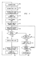
- FIG 1 is an overview of the methodology utilized in the present invention.
- the monitoring system is in calibration mode in its normal steady state configuration mode as shown in step 100. Calibration mode is discussed in greater detail in Figure 5 below.
- the customer orders a product after placing money in the ordering system by depressing a keypad or similar device in step 102.
- the vending machine's ordering system sends a customer order event signal in step 103 to the monitoring system informing the sensing/monitoring system that an order event has occurred in step 102.
- the monitoring system subsequently completes its last calibration cycle in step 104 and transitions from steady state calibration mode to the monitoring cycle in step 106.
- the monitoring system Upon transitioning, the monitoring system commences its sensing/monitoring cycle by monitoring the product delivery path and sends a ready signal to the product delivery system in step 110.
- the monitoring cycle is described in more detail in Figure 4 , herein below.
- the product delivery system After receiving a ready signal from the monitoring system, the product delivery system attempts to deliver a product through the product delivery path in step 120. If the monitoring system senses or detects the product passing through the delivery path in step 125, it reports the delivery event to the ordering system in step 130. Upon receiving the report, the ordering system concludes the transaction with the customer and sends a completion signal to the monitoring system, which returns to steady state calibration mode in step 135, whereupon the monitoring system enters into calibration mode in step 140.
- the monitoring system does not detect a product in the first delivery attempt in step 125 then it will not send a signal to the ordering system after the step 125.
- the invention allows the delivery system to attempt delivery three times or a preset option. In step 150, if the number of attempted delivery cycles is less than the preset option, then the ordering system thereupon attempts to deliver the product again in step 120. If the attempted delivery cycles equal the preset option, then in step 155 the customer is granted alternatives to purchasing the first ordered product. Step 155 allows the customer to either ask for a refund or make a selection of a second, different product for delivery and step 153 marks the first ordered product as empty.
- Step 153 prevents future vend attempts for the first ordered product until the vending machine is visited by a service person. This helps to prevent cheating of a customer if the vending machine reverts to the home switch operation, and helps to prevent further tampering if tampering was the cause of the first vend failure.
- the present invention delivers a signal to make a refund, in step 160, whereupon a signal is sent to the monitoring system that the order is complete in step 135 and to the monitoring system to enters into steady state calibration mode in step 140. If the customer choose a second, different product, then the present invention returns to 120 and the process proceeds as described above, until the operation is complete.
- FIG. 2 shows a schematic diagram of the present invention installed in a vending machine 205.
- various products 210 are placed in the vending machine's delivery system 215.
- the monitoring system 217 Prior to a customer making a purchase, the monitoring system 217 is in calibration mode.
- the ordering system allows for an attempted delivery of the ordered product 210, typically through a helical delivery system 215.
- product 270 is delivered into delivery space 222, falling through the delivery path 225 past monitoring system 217. As it passes the monitoring system, the product momentarily breaks the continuity of the monitoring system's monitoring devices.
- the monitoring system utilizes an optical monitoring system
- the monitoring system's light plane 234 be it infrared or otherwise, it momentarily breaks the light continuity and prevents a portion of the light from reaching at least one detector on the opposite side of the monitoring path.
- the logic circuit on the detecting arm 235 will note the momentary blockage of light and report it as a delivery event.
- the monitoring system is comprised of an emitter arm 240 upon which are located a set number of one or more emitters 242, and a detector arm 250 comprising of one or more detectors 252 and located directly across delivery path 225 from the emitter arm 240.
- Emitter signals the total of which comprise light plane 234 are sent from the emitters 242 to the detectors 252 across the delivery path 225, during both monitoring mode and calibration mode.
- the emitter arm 240 and the detector arm 250 may be located in various positions.
- the arms may be in a position that mirrors the one shown, among others.
- the emitter arms and detector arms are described in more detail in Figures 3A , and 3B .
- Figure 3A shows the emitter arm portion of the monitoring system.
- emitting arm 310A transverses along one side of the delivery path in the vending machine.
- Emitters, 315A are attached to arm 310A.
- the horizontal and vertical placement of emitters 315A on arm 310A is determined by the size of the smallest product that crosses the delivery path, and by the type and accuracy of the emitters utilized in the present invention.
- the emitters may comprise of an optical monitoring device.
- the spacing of optical emitters is determined by five factors: emitter size, optical diffusion, ambient light, product size and the reflected light. Emitter size and optical diffusion is fixed at the time of construction, however, ambient and reflective light may vary over the course of use of the emitter. Infrared light may be used to help to reduce these effects. However, it is clearly understood and contemplated by the present invention that other types of light sources can be used, including various lasers or white light sources.
- the body 320A of the arm 310A is made of suitable material able to contain the electronic control components 325A necessary to operate the emitter, including, a power source 330A, and logic circuitry 335A. Additionally, holes 340A are provided to securely fasten and adjust the positioning of the arm 310A to the vending machine.
- Figure 3B shows the detector arm portion of the monitoring system.
- the shape and construction of the detecting arm 350B is related to the shape and construction of the emitting arm 310A.
- the detecting arm 350B is placed on the same plane, parallel to and across the delivery path from arm 310A (see Figure 2 for more details).
- the detectors 355B are arranged so that their vertical spacing and horizontal arrangement mirror the emitter's arrangement on arm 310A.
- the body 360B of 350B is constructed of material suitable to contain detection and logic circuitry 365B, attachment holes 370B, and a power source 375B. The choice of the type of detector is directly related to the type of emitter being utilized in the present invention.
- the emitting arm 310A and the detector arm 350B may or may not have power sources, electronic control components, and logic circuitry.
- the detector arm may have a power source, electronic component, and logic circuitry that connects to the emitters thereby eliminating the power source and logic circuitry on the emitter arm.
- the emitter arm may have the power source, electronic components, and logic circuitry and the detector arm not.
- the power sources, electronic control components, and logic circuitries may be located separately from, together with, or in various combinations with the arms.
- FIG. 4 shows the operation of the monitoring system when a customer places an order.
- the monitoring system Prior to placing an order, the monitoring system is in calibration mode in step 400.
- the monitoring system transitions from its steady state calibration mode 400 into its monitoring mode in step 407.
- the monitoring system begins cycling each emitter by pulsing the emitter individually in step 410.
- the monitoring system uses a pulse strength determined when the system was in the calibration mode.
- step 410 an emitter pulses its signal to the corresponding detector across from the emitter, and the two detectors on either side of the detector.
- the detector circuitry determines whether the detectors detected the light from the emitter in step 415. (If the emitter is either the first emitter or the last emitter on the emitter arm, then only the detector across from the emitter and the detector on the non-wall side of the detector is scanned.)
- the emitter's logic circuit sequences to the next emitter in line and sends a pulse from that emitter in step 420.
- the emitter's logic circuit continues until it completes the pulsing of the last detector whereupon, the monitoring system repeats the process, and begins again at the first emitter until the detector's logic circuit receives a detect signal and/or the monitoring system receives a signal to cease monitoring.
- the logic circuit reports a product delivery to the ordering system in step 425. Once a report of delivery is made to the ordering system, the ordering system returns a signal to the monitoring system to return to steady state calibration mode in step 430. Otherwise, the monitoring system continues to monitor until it receives a return to steady state calibration signal from the ordering system.
- Figure 5 shows the steady state calibration mode of the monitoring system.
- the monitoring system is constantly calibrating itself for optimum performance because temperature, humidity, dust, and alignment conditions fluctuate over the course of system usage.
- the calibration mode adjusts the light intensity from each emitter as necessary so that each set of three detectors serviced by that emitter receives only enough intensity, plus a small safety margin, to be active in the unblocked condition. This minimizes the adverse affects of reflected light from the emitters and allows for a wider detector aperture (which makes system alignment easier) and reduces the overall power requirements of the system.
- the logic circuit in the monitoring system determines whether an order has been placed. If an order has not been placed, then the monitoring system proceeds to send a series of pulses to the first of the one or more emitters in step 510.
- the monitoring system Upon sending a pulse, the monitoring system queries the emitter's corresponding detector and each detector on either side of the corresponding detector to determine if those detectors detected the pulsed signal in step 515. If a signal was detected in each of the three detectors then the monitoring circuitry sequences to the next emitter in step 520.
- the emitter's typically have adjustable signal power levels associated with the type of emitter used. The calibration mode will attempt to maintain the power level at the level needed to provide just enough signal, plus a safety margin, such that the corresponding detectors detect the signal. If any one of the three detectors does not detect the pulsed signal from the emitter, then in step 530, the monitoring circuitry determines whether the emitter is operating at its maximum power intensity.
- the emitter will step increase the signal power level in step 560 and re-send a pulsed signal to the detectors again in step 510. If the power intensity for that emitter is at its maximum intensity, then the detector will send an error message to the monitoring system in step 540. The monitoring system will then follow a pre-coded routine to shut down the entire vending operation, shut down the monitoring system or rely on prior art ordering systems (the home switch method) in step 550.
- Figure 6 shows a typical detector arm attached to a vending machine. Because of the reflective surfaces 610 in the vending machine, small apertures 620 are used to minimize the reflective light from adjacently reflective surfaces 610.
- the apertures are narrowed holes located in front of the detectors, 625, on the detector side of sensing system 630. The holes inhibit unwanted reflections from adjacent surfaces by blocking much of the light beams that reflect back to the detector arm at wider angles than the apertures allow.
- Apertures 620 keep the majority of the unwanted light from reaching the detection side of the monitoring system.
- the detectors 630 have a usable 60-degree horizontal/30 degree vertical reception angle. Light arriving at the detector at angles greater than these is rejected.
- infrared optical detectors contain optical frequency filters, which reject visible light frequencies, but pass the infrared frequencies of interest. Modulation techniques, whereby the detector only responds to certain signal frequencies from the infrared emitters may also be used to allow the detectors to distinguish between the ambient light and the desired point source light frequency from the emitter.
- product detection may be accomplished by utilizing infrared emitter/detector pairs that can monitor and detect when a signal path is broken.
- infrared emitter/detector pairs that can monitor and detect when a signal path is broken.
- a set of ten infrared emitter/detector pairs are used to cover the delivery path much like a light curtain.
- Figure 7 shows a representative example of a light curtain 730 that may be utilized in the present invention.
- nine sets of emitters/detectors are used to cover the main delivery path, while the tenth set is used to cover a gum/mint area.
- the nine sets that cover the main delivery path implement a technique, which, other than for the first and last emitter, requires that, a minimum of three detectors are active for each individual emitter monitor cycle.
- the tenth emitter may be used for the main delivery area, provided that proper alignment of the ten sets is taken into consideration.
- FIG. 7 shows the light beams 710 of interest for each emitter 720 and detector 725.
- the spacing of the emitter/detector sets are chosen to assure that the smallest size traditional product breaks the path of at least one beam when it crosses the light curtain during delivery.
- the technique of servicing three detectors for each emitter allows the monitor to read multiple light beams, which further reduces this spacing in the majority of the delivery area.
- a logic circuit determines whether a light beam has been broken.
- the infrared emitter/detector sets are controlled by a microcontroller located on the detector arm.
- a microcontroller located on the detector arm.
- the timing sequence for each set monitor cycle used during the monitoring mode must be fast enough to ensure that the smallest product will be detected by any one of the detectors when the product passes the monitor plane as it falls from the product storage area.
- the control software may further provide the vending operator options to revert to home switch operation, to use a delivery method other than home switch operation, or to place the vending machine out of service in the event the monitoring system is inoperative.
- the operator may chose to revert to go out-of service and prevent erred delivery of the ordered product, all product, or some combination of products. In this manner, theft may be prevented.
- the customer may be offered a refund or the option of selecting another product.
- Another option may provide for the machine to return to home switch operation. If the monitoring system malfunctions, returning to home switch operation may permit continued service by the machine.
- a further option may provide for the machine to operate in a manner other than home switch operation. For example, upon a first delivery failure, the machine may move from a home position until a product is delivered and stop.
- Figure 8 depicts an exemplary embodiment of a method other than home switch operation.
- the machine may wait for an order.
- the delivery mechanism may move to the home position.
- the machine may rest at a home position, moving from the home position and returning to the home position.
- product may typically be delivered with each turn of the helix.
- the helix rests at a home position and turns one revolution to deliver the product, returning to the home position.
- the machine returns to waiting for another order, as seen in a block 804. However, if a delivery is not detected, the machine may gradually or at a continuous speed move from the home position until a delivery is detected or the delivery mechanism returns to the home position. As seen in the blocks 808 and 810, if a delivery is detected while the delivery mechanism is moving, the mechanism is stopped and the machine awaits another order. If another order is made, the machine returns to the home position. In this manner, if a first item is stuck, a second item may move it forward causing a delivery. By stopping the mechanism, delivery of the second item may be prevented.
- an error or delivery failure may be detected as seen in a block 814.
- the machine may count the number of passes through the home position and disable delivery of the product, all products, and/or offer a refund or credit once a preset number of passes is exceeded.
- the monitoring system controller printed circuit board uses flash memory to store the firmware. This gives the option to perform firmware updates in the field.
- the vending system may have several operating options. In one exemplary embodiment, These may be viewed and programmed by pressing the PRODUCT CONFIG service key on the keypad located on the inside of the vending machine and pressing the down arrow until the appropriate option is reached.
- the keypad has an associated display device, such as an led screen or such other typical devices that allow the operator to view the code and results stored within the system.
- the vendor can choose between "SURE.V ON” or “SURE.V OFF". "SURE.V OFF" is chosen by the operator only if the monitoring system is not installed or if the operator does not wish it to use it at the present time. The remaining options for the PRODUCT CONFIG mode are only visible if "SURE.V ON" is selected and the monitoring system is available.
- the operator may then choose between "OPT'N SURE.V” or “MUST SURE.V". If “OPT'N SURE.V” is selected, the vending machine operation reverts to home switch operation if the monitoring system is not operating normally because, for example, of an obstruction or loss of communication. If “MUST SURE.V” is selected by the operator, the vending machine operates only if the monitoring system is available for use for the main delivery area. (The gum and mint area does not affect operation of the main area, unless the programmer decides otherwise.) Otherwise, the vending machine becomes temporarily out-of-service until the blockage or other error is corrected.
- the vending machine either reverts to home switch operation if "OPT'N SURE.V” is active, or the system deactivates and the vending machine goes out of service if "MUST SURE.V” is active. If in “Must Sure.V", once the programmed deactivation time has elapsed the system is re-enabled and the count towards "xx" is restarted. The total number of system empty selections, the number of anti-jackpot occurrences, and the date and time of the last occurrence are recorded as noted below.
- the operator programs the number of minutes that the vending system remains disabled because of an anti-jackpot occurrence by selecting the "AJP.TMR xxM” option where "xx" is the time in minutes. If "99" is programmed, then the system remains disabled until the main door closes at the end of the next service call. Closing the main door also resets any anti-jackpot time remaining.
- the TEST list provides the test screen for the system. If the operator keys in "SV.TST xxx", the following options are provided:
- a calibration value of "0" indicates a shorted detector. This normally requires a new detector assembly.
- a calibration value of "1" indicates that zone could not be calibrated. It indicates a blocked or damaged sensor.
- SV.TST COMM indicates loss of communication with the monitoring system, and allows the operation to check the harness connections between the vending machine controller and the monitoring system's controller.
Landscapes
- Physics & Mathematics (AREA)
- General Physics & Mathematics (AREA)
- Business, Economics & Management (AREA)
- Accounting & Taxation (AREA)
- Control Of Vending Devices And Auxiliary Devices For Vending Devices (AREA)
- Geophysics And Detection Of Objects (AREA)
- Burglar Alarm Systems (AREA)
Priority Applications (1)
| Application Number | Priority Date | Filing Date | Title |
|---|---|---|---|
| EP10183519A EP2267670A1 (en) | 2002-06-19 | 2002-06-19 | Method and system for accomplishing product detection |
Applications Claiming Priority (1)
| Application Number | Priority Date | Filing Date | Title |
|---|---|---|---|
| PCT/US2002/019292 WO2004001687A1 (en) | 2002-06-19 | 2002-06-19 | Method and system for accomplishing product detection |
Related Child Applications (1)
| Application Number | Title | Priority Date | Filing Date |
|---|---|---|---|
| EP10183519.7 Division-Into | 2010-09-30 |
Publications (2)
| Publication Number | Publication Date |
|---|---|
| EP1522055A1 EP1522055A1 (en) | 2005-04-13 |
| EP1522055B1 true EP1522055B1 (en) | 2011-09-14 |
Family
ID=29998717
Family Applications (1)
| Application Number | Title | Priority Date | Filing Date |
|---|---|---|---|
| EP02744414A Expired - Lifetime EP1522055B1 (en) | 2002-06-19 | 2002-06-19 | System and apparatus for accomplishing product detection |
Country Status (9)
| Country | Link |
|---|---|
| EP (1) | EP1522055B1 (en:Method) |
| AT (1) | ATE524797T1 (en:Method) |
| AU (1) | AU2002318354B2 (en:Method) |
| CA (1) | CA2489788C (en:Method) |
| DK (1) | DK1522055T3 (en:Method) |
| ES (1) | ES2372812T3 (en:Method) |
| MX (1) | MXPA05000179A (en:Method) |
| NZ (1) | NZ537317A (en:Method) |
| WO (1) | WO2004001687A1 (en:Method) |
Families Citing this family (4)
| Publication number | Priority date | Publication date | Assignee | Title |
|---|---|---|---|---|
| ITVR20040068A1 (it) * | 2004-04-21 | 2004-07-21 | Fas International Spa | Dispositivo a barriera ottica |
| ITTO20040303A1 (it) * | 2004-05-10 | 2004-08-10 | Novarese Michele | Perfezionamenti in un distributore automatico per articoli |
| ES2627740B1 (es) * | 2015-09-18 | 2018-01-26 | María Jorgelina FAVA | Máquina expendedora desasistida de bombonas de butano |
| CN112200969A (zh) * | 2020-09-01 | 2021-01-08 | 深圳市智莱科技股份有限公司 | 出货故障处理方法、自动售卖机和计算机可读存储介质 |
Family Cites Families (4)
| Publication number | Priority date | Publication date | Assignee | Title |
|---|---|---|---|---|
| US4252250A (en) * | 1978-09-28 | 1981-02-24 | Umc Industries, Inc. | Multiple-beam optical sensing system for an article vendor |
| US4359147A (en) * | 1979-08-06 | 1982-11-16 | H. R. Electronics Company | Means to control vending functions |
| US6384402B1 (en) * | 1998-04-29 | 2002-05-07 | Automated Merchandising Systems | Optical vend-sensing system for control of vending machine |
| DE20006317U1 (de) * | 2000-04-06 | 2000-10-19 | Stiefel GmbH, 75038 Oberderdingen | Vorrichtung zur Erkennung eines Gegenstands |
-
2002
- 2002-06-19 AT AT02744414T patent/ATE524797T1/de active
- 2002-06-19 AU AU2002318354A patent/AU2002318354B2/en not_active Ceased
- 2002-06-19 WO PCT/US2002/019292 patent/WO2004001687A1/en not_active Ceased
- 2002-06-19 NZ NZ537317A patent/NZ537317A/en unknown
- 2002-06-19 EP EP02744414A patent/EP1522055B1/en not_active Expired - Lifetime
- 2002-06-19 MX MXPA05000179A patent/MXPA05000179A/es active IP Right Grant
- 2002-06-19 CA CA2489788A patent/CA2489788C/en not_active Expired - Lifetime
- 2002-06-19 ES ES02744414T patent/ES2372812T3/es not_active Expired - Lifetime
- 2002-06-19 DK DK02744414.0T patent/DK1522055T3/da active
Also Published As
| Publication number | Publication date |
|---|---|
| AU2002318354A1 (en) | 2004-01-06 |
| MXPA05000179A (es) | 2005-06-06 |
| EP1522055A1 (en) | 2005-04-13 |
| ES2372812T3 (es) | 2012-01-26 |
| DK1522055T3 (da) | 2011-12-12 |
| CA2489788C (en) | 2014-01-28 |
| AU2002318354B2 (en) | 2009-09-03 |
| CA2489788A1 (en) | 2003-12-31 |
| NZ537317A (en) | 2007-05-31 |
| WO2004001687A1 (en) | 2003-12-31 |
| ATE524797T1 (de) | 2011-09-15 |
Similar Documents
| Publication | Publication Date | Title |
|---|---|---|
| US6732014B2 (en) | System for accomplishing product detection | |
| US7980418B2 (en) | Method and system for accomplishing product detection | |
| US8548625B2 (en) | Optical vend sensing system for product delivery detection | |
| US6003651A (en) | Sensing of coin output from a gaming device to reduce incorrect number of coins output | |
| US5980089A (en) | Automatic token dispensing apparatus and method | |
| US7343220B2 (en) | Optical vend-sensing system for control of vending machine | |
| US6920372B2 (en) | Audit monitoring and product drop system for retrofitting vending machines | |
| EP1522055B1 (en) | System and apparatus for accomplishing product detection | |
| US7519451B2 (en) | Apparatus and methodology of detecting fulfillment of customer vend request | |
| EP2267670A1 (en) | Method and system for accomplishing product detection | |
| US7565222B2 (en) | Economical optical system to provide reasonable assurance of completed vend or vendible items from vending machines | |
| AU2002349919A1 (en) | Apparatus and methodology of detecting fulfillment of customer vend request | |
| US20130328689A1 (en) | Medium processor notifying when servicing is required | |
| KR102901402B1 (ko) | 자판기의 상품감지 메트릭스 센서 시스템 및 그 제어방법 | |
| JP3016523B2 (ja) | パチンコホール用貸出装置 | |
| JP2001155226A (ja) | 自動販売機 | |
| JPS5860275A (ja) | 自動販売機におけるセンサ異常予報方法 | |
| KR20030071165A (ko) | 자동판매기 |
Legal Events
| Date | Code | Title | Description |
|---|---|---|---|
| PUAI | Public reference made under article 153(3) epc to a published international application that has entered the european phase |
Free format text: ORIGINAL CODE: 0009012 |
|
| 17P | Request for examination filed |
Effective date: 20050117 |
|
| AK | Designated contracting states |
Kind code of ref document: A1 Designated state(s): AT BE CH CY DE DK ES FI FR GB GR IE IT LI LU MC NL PT SE TR |
|
| AX | Request for extension of the european patent |
Extension state: AL LT LV MK RO SI |
|
| DAX | Request for extension of the european patent (deleted) | ||
| 17Q | First examination report despatched |
Effective date: 20070521 |
|
| GRAP | Despatch of communication of intention to grant a patent |
Free format text: ORIGINAL CODE: EPIDOSNIGR1 |
|
| RTI1 | Title (correction) |
Free format text: SYSTEM AND APPARATUS FOR ACCOMPLISHING PRODUCT DETECTION |
|
| GRAS | Grant fee paid |
Free format text: ORIGINAL CODE: EPIDOSNIGR3 |
|
| GRAA | (expected) grant |
Free format text: ORIGINAL CODE: 0009210 |
|
| AK | Designated contracting states |
Kind code of ref document: B1 Designated state(s): AT BE CH CY DE DK ES FI FR GB GR IE IT LI LU MC NL PT SE TR |
|
| REG | Reference to a national code |
Ref country code: GB Ref legal event code: FG4D |
|
| REG | Reference to a national code |
Ref country code: CH Ref legal event code: EP |
|
| REG | Reference to a national code |
Ref country code: IE Ref legal event code: FG4D |
|
| REG | Reference to a national code |
Ref country code: DE Ref legal event code: R096 Ref document number: 60241034 Country of ref document: DE Effective date: 20111103 |
|
| REG | Reference to a national code |
Ref country code: DK Ref legal event code: T3 |
|
| REG | Reference to a national code |
Ref country code: SE Ref legal event code: TRGR |
|
| REG | Reference to a national code |
Ref country code: NL Ref legal event code: T3 |
|
| REG | Reference to a national code |
Ref country code: ES Ref legal event code: FG2A Ref document number: 2372812 Country of ref document: ES Kind code of ref document: T3 Effective date: 20120126 |
|
| PG25 | Lapsed in a contracting state [announced via postgrant information from national office to epo] |
Ref country code: FI Free format text: LAPSE BECAUSE OF FAILURE TO SUBMIT A TRANSLATION OF THE DESCRIPTION OR TO PAY THE FEE WITHIN THE PRESCRIBED TIME-LIMIT Effective date: 20110914 |
|
| PG25 | Lapsed in a contracting state [announced via postgrant information from national office to epo] |
Ref country code: CY Free format text: LAPSE BECAUSE OF FAILURE TO SUBMIT A TRANSLATION OF THE DESCRIPTION OR TO PAY THE FEE WITHIN THE PRESCRIBED TIME-LIMIT Effective date: 20110914 Ref country code: GR Free format text: LAPSE BECAUSE OF FAILURE TO SUBMIT A TRANSLATION OF THE DESCRIPTION OR TO PAY THE FEE WITHIN THE PRESCRIBED TIME-LIMIT Effective date: 20111215 |
|
| PG25 | Lapsed in a contracting state [announced via postgrant information from national office to epo] |
Ref country code: PT Free format text: LAPSE BECAUSE OF FAILURE TO SUBMIT A TRANSLATION OF THE DESCRIPTION OR TO PAY THE FEE WITHIN THE PRESCRIBED TIME-LIMIT Effective date: 20120116 |
|
| PLBE | No opposition filed within time limit |
Free format text: ORIGINAL CODE: 0009261 |
|
| STAA | Information on the status of an ep patent application or granted ep patent |
Free format text: STATUS: NO OPPOSITION FILED WITHIN TIME LIMIT |
|
| 26N | No opposition filed |
Effective date: 20120615 |
|
| REG | Reference to a national code |
Ref country code: DE Ref legal event code: R097 Ref document number: 60241034 Country of ref document: DE Effective date: 20120615 |
|
| PG25 | Lapsed in a contracting state [announced via postgrant information from national office to epo] |
Ref country code: MC Free format text: LAPSE BECAUSE OF NON-PAYMENT OF DUE FEES Effective date: 20120630 |
|
| REG | Reference to a national code |
Ref country code: IE Ref legal event code: MM4A |
|
| PGFP | Annual fee paid to national office [announced via postgrant information from national office to epo] |
Ref country code: AT Payment date: 20120710 Year of fee payment: 11 |
|
| PG25 | Lapsed in a contracting state [announced via postgrant information from national office to epo] |
Ref country code: IE Free format text: LAPSE BECAUSE OF NON-PAYMENT OF DUE FEES Effective date: 20120619 |
|
| PGFP | Annual fee paid to national office [announced via postgrant information from national office to epo] |
Ref country code: DK Payment date: 20130628 Year of fee payment: 12 |
|
| PGFP | Annual fee paid to national office [announced via postgrant information from national office to epo] |
Ref country code: TR Payment date: 20130619 Year of fee payment: 12 |
|
| PGFP | Annual fee paid to national office [announced via postgrant information from national office to epo] |
Ref country code: BE Payment date: 20130712 Year of fee payment: 12 Ref country code: SE Payment date: 20130628 Year of fee payment: 12 Ref country code: DE Payment date: 20130703 Year of fee payment: 12 Ref country code: ES Payment date: 20130711 Year of fee payment: 12 Ref country code: NL Payment date: 20130628 Year of fee payment: 12 |
|
| PGFP | Annual fee paid to national office [announced via postgrant information from national office to epo] |
Ref country code: FR Payment date: 20130725 Year of fee payment: 12 Ref country code: GB Payment date: 20130703 Year of fee payment: 12 |
|
| PGFP | Annual fee paid to national office [announced via postgrant information from national office to epo] |
Ref country code: IT Payment date: 20130701 Year of fee payment: 12 |
|
| REG | Reference to a national code |
Ref country code: CH Ref legal event code: PL |
|
| PG25 | Lapsed in a contracting state [announced via postgrant information from national office to epo] |
Ref country code: LI Free format text: LAPSE BECAUSE OF NON-PAYMENT OF DUE FEES Effective date: 20130630 Ref country code: CH Free format text: LAPSE BECAUSE OF NON-PAYMENT OF DUE FEES Effective date: 20130630 |
|
| PG25 | Lapsed in a contracting state [announced via postgrant information from national office to epo] |
Ref country code: LU Free format text: LAPSE BECAUSE OF NON-PAYMENT OF DUE FEES Effective date: 20120619 |
|
| REG | Reference to a national code |
Ref country code: DE Ref legal event code: R119 Ref document number: 60241034 Country of ref document: DE |
|
| REG | Reference to a national code |
Ref country code: DK Ref legal event code: EBP Effective date: 20140630 |
|
| REG | Reference to a national code |
Ref country code: NL Ref legal event code: V1 Effective date: 20150101 |
|
| PG25 | Lapsed in a contracting state [announced via postgrant information from national office to epo] |
Ref country code: SE Free format text: LAPSE BECAUSE OF NON-PAYMENT OF DUE FEES Effective date: 20140620 |
|
| REG | Reference to a national code |
Ref country code: SE Ref legal event code: EUG |
|
| REG | Reference to a national code |
Ref country code: AT Ref legal event code: MM01 Ref document number: 524797 Country of ref document: AT Kind code of ref document: T Effective date: 20140619 |
|
| GBPC | Gb: european patent ceased through non-payment of renewal fee |
Effective date: 20140619 |
|
| REG | Reference to a national code |
Ref country code: FR Ref legal event code: ST Effective date: 20150227 |
|
| PG25 | Lapsed in a contracting state [announced via postgrant information from national office to epo] |
Ref country code: NL Free format text: LAPSE BECAUSE OF NON-PAYMENT OF DUE FEES Effective date: 20150101 |
|
| REG | Reference to a national code |
Ref country code: DE Ref legal event code: R119 Ref document number: 60241034 Country of ref document: DE Effective date: 20150101 |
|
| PG25 | Lapsed in a contracting state [announced via postgrant information from national office to epo] |
Ref country code: DE Free format text: LAPSE BECAUSE OF NON-PAYMENT OF DUE FEES Effective date: 20150101 Ref country code: IT Free format text: LAPSE BECAUSE OF NON-PAYMENT OF DUE FEES Effective date: 20140619 |
|
| PG25 | Lapsed in a contracting state [announced via postgrant information from national office to epo] |
Ref country code: FR Free format text: LAPSE BECAUSE OF NON-PAYMENT OF DUE FEES Effective date: 20140630 Ref country code: AT Free format text: LAPSE BECAUSE OF NON-PAYMENT OF DUE FEES Effective date: 20140619 Ref country code: GB Free format text: LAPSE BECAUSE OF NON-PAYMENT OF DUE FEES Effective date: 20140619 |
|
| REG | Reference to a national code |
Ref country code: ES Ref legal event code: FD2A Effective date: 20150724 |
|
| PG25 | Lapsed in a contracting state [announced via postgrant information from national office to epo] |
Ref country code: DK Free format text: LAPSE BECAUSE OF NON-PAYMENT OF DUE FEES Effective date: 20140630 |
|
| PG25 | Lapsed in a contracting state [announced via postgrant information from national office to epo] |
Ref country code: ES Free format text: LAPSE BECAUSE OF NON-PAYMENT OF DUE FEES Effective date: 20140620 |
|
| PG25 | Lapsed in a contracting state [announced via postgrant information from national office to epo] |
Ref country code: BE Free format text: LAPSE BECAUSE OF NON-PAYMENT OF DUE FEES Effective date: 20140630 |
|
| PG25 | Lapsed in a contracting state [announced via postgrant information from national office to epo] |
Ref country code: TR Free format text: LAPSE BECAUSE OF NON-PAYMENT OF DUE FEES Effective date: 20140619 |