EP1521660B1 - Use of a fluxing apparatus for applying powdered flux - Google Patents
Use of a fluxing apparatus for applying powdered flux Download PDFInfo
- Publication number
- EP1521660B1 EP1521660B1 EP03761061A EP03761061A EP1521660B1 EP 1521660 B1 EP1521660 B1 EP 1521660B1 EP 03761061 A EP03761061 A EP 03761061A EP 03761061 A EP03761061 A EP 03761061A EP 1521660 B1 EP1521660 B1 EP 1521660B1
- Authority
- EP
- European Patent Office
- Prior art keywords
- fluxing
- flux
- set forth
- powdered flux
- chamber
- Prior art date
- Legal status (The legal status is an assumption and is not a legal conclusion. Google has not performed a legal analysis and makes no representation as to the accuracy of the status listed.)
- Expired - Lifetime
Links
Images




Classifications
-
- B—PERFORMING OPERATIONS; TRANSPORTING
- B05—SPRAYING OR ATOMISING IN GENERAL; APPLYING FLUENT MATERIALS TO SURFACES, IN GENERAL
- B05B—SPRAYING APPARATUS; ATOMISING APPARATUS; NOZZLES
- B05B7/00—Spraying apparatus for discharge of liquids or other fluent materials from two or more sources, e.g. of liquid and air, of powder and gas
- B05B7/14—Spraying apparatus for discharge of liquids or other fluent materials from two or more sources, e.g. of liquid and air, of powder and gas designed for spraying particulate materials
- B05B7/1404—Arrangements for supplying particulate material
- B05B7/144—Arrangements for supplying particulate material the means for supplying particulate material comprising moving mechanical means
-
- B—PERFORMING OPERATIONS; TRANSPORTING
- B05—SPRAYING OR ATOMISING IN GENERAL; APPLYING FLUENT MATERIALS TO SURFACES, IN GENERAL
- B05B—SPRAYING APPARATUS; ATOMISING APPARATUS; NOZZLES
- B05B12/00—Arrangements for controlling delivery; Arrangements for controlling the spray area
- B05B12/08—Arrangements for controlling delivery; Arrangements for controlling the spray area responsive to condition of liquid or other fluent material to be discharged, of ambient medium or of target ; responsive to condition of spray devices or of supply means, e.g. pipes, pumps or their drive means
- B05B12/12—Arrangements for controlling delivery; Arrangements for controlling the spray area responsive to condition of liquid or other fluent material to be discharged, of ambient medium or of target ; responsive to condition of spray devices or of supply means, e.g. pipes, pumps or their drive means responsive to conditions of ambient medium or target, e.g. humidity, temperature position or movement of the target relative to the spray apparatus
- B05B12/122—Arrangements for controlling delivery; Arrangements for controlling the spray area responsive to condition of liquid or other fluent material to be discharged, of ambient medium or of target ; responsive to condition of spray devices or of supply means, e.g. pipes, pumps or their drive means responsive to conditions of ambient medium or target, e.g. humidity, temperature position or movement of the target relative to the spray apparatus responsive to presence or shape of target
-
- B—PERFORMING OPERATIONS; TRANSPORTING
- B05—SPRAYING OR ATOMISING IN GENERAL; APPLYING FLUENT MATERIALS TO SURFACES, IN GENERAL
- B05B—SPRAYING APPARATUS; ATOMISING APPARATUS; NOZZLES
- B05B14/00—Arrangements for collecting, re-using or eliminating excess spraying material
- B05B14/40—Arrangements for collecting, re-using or eliminating excess spraying material for use in spray booths
- B05B14/48—Arrangements for collecting, re-using or eliminating excess spraying material for use in spray booths specially adapted for particulate material
-
- B—PERFORMING OPERATIONS; TRANSPORTING
- B05—SPRAYING OR ATOMISING IN GENERAL; APPLYING FLUENT MATERIALS TO SURFACES, IN GENERAL
- B05B—SPRAYING APPARATUS; ATOMISING APPARATUS; NOZZLES
- B05B16/00—Spray booths
- B05B16/90—Spray booths comprising conveying means for moving objects or other work to be sprayed in and out of the booth, e.g. through the booth
- B05B16/95—Spray booths comprising conveying means for moving objects or other work to be sprayed in and out of the booth, e.g. through the booth the objects or other work to be sprayed lying on, or being held above the conveying means, i.e. not hanging from the conveying means
-
- B—PERFORMING OPERATIONS; TRANSPORTING
- B05—SPRAYING OR ATOMISING IN GENERAL; APPLYING FLUENT MATERIALS TO SURFACES, IN GENERAL
- B05B—SPRAYING APPARATUS; ATOMISING APPARATUS; NOZZLES
- B05B7/00—Spraying apparatus for discharge of liquids or other fluent materials from two or more sources, e.g. of liquid and air, of powder and gas
- B05B7/14—Spraying apparatus for discharge of liquids or other fluent materials from two or more sources, e.g. of liquid and air, of powder and gas designed for spraying particulate materials
- B05B7/1404—Arrangements for supplying particulate material
- B05B7/1454—Arrangements for supplying particulate material comprising means for supplying collected oversprayed particulate material
-
- B—PERFORMING OPERATIONS; TRANSPORTING
- B23—MACHINE TOOLS; METAL-WORKING NOT OTHERWISE PROVIDED FOR
- B23K—SOLDERING OR UNSOLDERING; WELDING; CLADDING OR PLATING BY SOLDERING OR WELDING; CUTTING BY APPLYING HEAT LOCALLY, e.g. FLAME CUTTING; WORKING BY LASER BEAM
- B23K1/00—Soldering, e.g. brazing, or unsoldering
- B23K1/20—Preliminary treatment of work or areas to be soldered, e.g. in respect of a galvanic coating
- B23K1/203—Fluxing, i.e. applying flux onto surfaces
-
- B—PERFORMING OPERATIONS; TRANSPORTING
- B23—MACHINE TOOLS; METAL-WORKING NOT OTHERWISE PROVIDED FOR
- B23K—SOLDERING OR UNSOLDERING; WELDING; CLADDING OR PLATING BY SOLDERING OR WELDING; CUTTING BY APPLYING HEAT LOCALLY, e.g. FLAME CUTTING; WORKING BY LASER BEAM
- B23K3/00—Tools, devices or special appurtenances for soldering, e.g. brazing, or unsoldering, not specially adapted for particular methods
- B23K3/08—Auxiliary devices therefor
- B23K3/082—Flux dispensers; Apparatus for applying flux
-
- B—PERFORMING OPERATIONS; TRANSPORTING
- B05—SPRAYING OR ATOMISING IN GENERAL; APPLYING FLUENT MATERIALS TO SURFACES, IN GENERAL
- B05B—SPRAYING APPARATUS; ATOMISING APPARATUS; NOZZLES
- B05B13/00—Machines or plants for applying liquids or other fluent materials to surfaces of objects or other work by spraying, not covered by groups B05B1/00 - B05B11/00
- B05B13/02—Means for supporting work; Arrangement or mounting of spray heads; Adaptation or arrangement of means for feeding work
- B05B13/04—Means for supporting work; Arrangement or mounting of spray heads; Adaptation or arrangement of means for feeding work the spray heads being moved during spraying operation
- B05B13/0405—Means for supporting work; Arrangement or mounting of spray heads; Adaptation or arrangement of means for feeding work the spray heads being moved during spraying operation with reciprocating or oscillating spray heads
- B05B13/041—Means for supporting work; Arrangement or mounting of spray heads; Adaptation or arrangement of means for feeding work the spray heads being moved during spraying operation with reciprocating or oscillating spray heads with spray heads reciprocating along a straight line
-
- B—PERFORMING OPERATIONS; TRANSPORTING
- B05—SPRAYING OR ATOMISING IN GENERAL; APPLYING FLUENT MATERIALS TO SURFACES, IN GENERAL
- B05B—SPRAYING APPARATUS; ATOMISING APPARATUS; NOZZLES
- B05B5/00—Electrostatic spraying apparatus; Spraying apparatus with means for charging the spray electrically; Apparatus for spraying liquids or other fluent materials by other electric means
- B05B5/08—Plant for applying liquids or other fluent materials to objects
- B05B5/082—Plant for applying liquids or other fluent materials to objects characterised by means for supporting, holding or conveying the objects
- B05B5/084—Plant for applying liquids or other fluent materials to objects characterised by means for supporting, holding or conveying the objects the objects lying on, or being supported above conveying means, e.g. conveyor belts
-
- Y—GENERAL TAGGING OF NEW TECHNOLOGICAL DEVELOPMENTS; GENERAL TAGGING OF CROSS-SECTIONAL TECHNOLOGIES SPANNING OVER SEVERAL SECTIONS OF THE IPC; TECHNICAL SUBJECTS COVERED BY FORMER USPC CROSS-REFERENCE ART COLLECTIONS [XRACs] AND DIGESTS
- Y02—TECHNOLOGIES OR APPLICATIONS FOR MITIGATION OR ADAPTATION AGAINST CLIMATE CHANGE
- Y02P—CLIMATE CHANGE MITIGATION TECHNOLOGIES IN THE PRODUCTION OR PROCESSING OF GOODS
- Y02P70/00—Climate change mitigation technologies in the production process for final industrial or consumer products
- Y02P70/10—Greenhouse gas [GHG] capture, material saving, heat recovery or other energy efficient measures, e.g. motor control, characterised by manufacturing processes, e.g. for rolling metal or metal working
Definitions
- the subject invention generally relates to the use of a fluxing apparatus for applying powdered flux to an object, such as a heat exchanger for a vehicle according to the preamble of claim 1 (see, for example, US-A- 5 174 490 ).
- Fluxing apparatuses or fluxers, are known in the art.
- a fluxer is utilized in combination with a core stacking machine, a thermal degreasing unit, and a brazing furnace to manufacture an object, such as a heat exchanger for a vehicle.
- the fluxer is utilized to apply flux to a surface or surfaces of the heat exchanger.
- the flux which is a caustic chemical that dissolves existing metal oxide and prevents the formation of metal oxide, melts just below the temperature at which a layer of braze material, that is previously clad to the surface of the heat exchanger, melts.
- the flux eliminates metal oxides which are detrimental to the wetting and flow of melted braze material into joint interfaces between the discrete components that make up the heat exchanger.
- a wet slurry flux there are two types of flux, a wet slurry flux and a powdered flux.
- Conventional fluxers apply the powdered flux to the heat exchanger in one of two manners.
- the heat exchanger is either processed through a fluidized bed of the powdered flux, or the powdered flux is spray applied onto the heat exchanger.
- the conventional fluxers that spray apply the powdered flux onto the heat exchangers are deficient for a variety of reasons. For instance, these conventional fluxers are prone to repeated failure and extensive service.
- the powdered flux which has a fine, yet abrasive, particle size, wears excessively on the working components of the conventional fluxers, such as the gun nozzles and delivery tubes for the powdered flux. Further, these conventional fluxers do not make efficient use of the powdered flux.
- the powdered flux that is overspray i.e., not adequately applied to the heat exchanger, is frequently allowed to exit the conventional fluxer. As a result, the factory or work area surrounding the conventional fluxers becomes contaminated with the powdered flux, which may create a safety hazard. Also, because the overspray is not recovered and recycled to be re-applied to other heat exchangers, significant amounts of the powdered flux are wasted which increases operating costs.
- US 5,174 , 490 discloses a fluxing apparatus comprising a water pre-spray to enable some flux overspray to be attracted to a side of a heat exchanger remote from the side sprayed. No recovery of oversprayed flux from the humid environment of US 5,174, 490 is disclosed.
- the conventional fluxers are also limited in that they are only equipped to flux certain types of heat exchangers depending on their size. That is, the conventional fluxers are not dynamic because they cannot detect and then accommodate heat exchangers of various sizes.
- the present invention is defined in claim 1. Further aspects of the present invention are defined in the dependent claims.
- the use of fluxing apparatus for applying powdered flux is disclosed.
- the fluxing apparatus applies powdered flux to an object.
- the fluxing apparatus integrates several components in including an enclosure, a conveyor, a supply hopper, at least one application device, and a flux recovery system.
- the enclosure defines a fluxing chamber for applying powdered flux where the object is fluxed.
- the enclosure includes an inlet and an outlet.
- the inlet receives the object into the fluxing chamber prior to application of the powdered flux and the outlet discharges the object from the fluxing chamber after the powdered flux has been applied.
- the conveyor extends through the enclosure between the inlet and the outlet. The conveyor traverses the object into and out of the fluxing chamber.
- the supply hopper stores the powdered flux
- the application device which is in fluid communication with the supply hopper and which is positioned to face at least one side of the conveyor, applies the powdered flux to the object.
- the flux recovery system is in fluid communication with the fluxing chamber.
- the flux recovery system introduces and maintains a negative pressure within the fluxing chamber. As such, excess powdered flux is retained within the enclosure. The excess powdered flux can be recovered and then recycled to the supply hopper.
- the subject invention provides the use of a fluxing apparatus that integrates the components described above to achieve synergistic benefits.
- the fluxing apparatus integrates components that have increased wear-resistance and, therefore, last longer in service.
- This fluxing apparatus also incorporates a flux recovery system that minimizes operating costs by retaining excess powdered flux within the apparatus and then recovering and recycling this flux.
- the fluxing apparatus utilizes less flux overall. Additionally, it is advantageous that the fluxing apparatus can detect varying shapes and sizes of heat exchangers and can then adjust to accommodate such different heat exchangers.
- a fluxing apparatus or fluxer
- the fluxing apparatus 10 applies powdered flux 11 to an object 12, such as a heat exchanger 12 for a vehicle.
- object 12 such as a heat exchanger 12 for a vehicle.
- the fluxing apparatus 10 can be used to apply powdered flux 11 to any object 12, its most preferred application is in the manufacture of heat exchangers 12. Accordingly, for descriptive purposes only, the object 12 is hereinafter referred to as the heat exchanger 12.
- the fluxing apparatus 10 is preferably utilized in a continuous method.
- the fluxing apparatus 10 continuously applies powdered flux 11 to a plurality of heat exchangers 12 that continuously traverse, or pass-through, the fluxing apparatus 10.
- the fluxing apparatus 10 applies powdered flux 11 to a plurality of heat exchangers 12, the subject invention is primarily described below in terms of a single heat exchanger 12.
- the fluxing apparatus 10 includes an enclosure 14, a conveyor 16, a supply hopper 18, at least one application device 20, and a flux recovery system 22. These components are described additionally below. As understood by those skilled in the art, the fluxing apparatus 10 is utilized in combination with a core stacking machine, a thermal degreasing unit, and a brazing furnace to manufacture the heat exchanger 12.
- the core stacking machine, thermal degreasing unit, and brazing furnace are not pertinent to the subject invention. Accordingly, these components are not disclosed in the Figures.
- the fluxing apparatus 10 includes the enclosure 14.
- the enclosure 14 includes an inlet 24 and an outlet 26 and defines a fluxing chamber 28.
- the inlet 24 of the enclosure 14 receives the heat exchanger 12 into the fluxing chamber 28 prior to application of the powdered flux 11, and the heat exchanger 12 is discharged from the outlet 26 of the enclosure 14 after the powdered flux 11 has been applied to the heat exchanger 12 by the application device 20 as described below.
- the fluxing apparatus 10 also includes the conveyor 16 that extends through the enclosure 14 through the between the inlet 24 and the outlet 26.
- the conveyor 16 traverses the object 12 into and out of the fluxing chamber 28.
- the heat exchanger 12 is mounted onto the conveyor 16 at or near the inlet 24 of the enclosure 14. Once on the conveyor 16, the heat exchanger 12 moves into the enclosure 14, into the fluxing chamber 28 where it is fluxed, and out of the enclosure 14 where the heat exchanger 12 then moves into the brazing furnace.
- the conveyor 16 is continuous such that the heat exchanger 12 moves through the enclosure 14 at a constant rate.
- the conveyor 16 may be intermittent such that the heat exchanger 12 is moved into the enclosure 14, stops in the fluxing chamber 28 to be fluxed, and then moves out of the enclosure 14 and into the brazing furnace.
- the type of conveyor 16 that may be utilized includes, but is not limited to, a belt-type conveyor, a rod belt-type conveyor, or a roller-type conveyor.
- the conveyor 16 may be a single, continuous unit, it is preferred that the conveyor 16 includes a plurality of conveyor sections 16A, 16B.
- at least one of the conveyor sections 16A is spaced from an adjacent conveyor section 16B to define an application gap 30 between the adjacent conveyor sections 16A, 16B.
- An underside of the heat exchanger 12 is, therefore, at least partially exposed at some point within the fluxing chamber 28. The importance of this partial exposure of the underside is described below.
- the fluxing apparatus 10 preferably includes an object recognition system 32 that is disposed adjacent the inlet 24 of the enclosure 14.
- the object recognition system 32 detects at least one dimension of the heat exchanger 12 before the powdered flux 11 is to be applied to the heat exchanger 12.
- the object recognition system 32 detects the length, width, and depth of the heat exchanger 12.
- the object recognition system 32 more specifically includes at least one laser 34 that detects the dimension or dimensions of the heat exchanger 12 prior to application of the powdered flux 11.
- the object recognition system 32 includes three lasers 34.
- the lasers 34 detect the length, width, and depth of the heat exchanger 12 or heat exchangers 12 that are traversing into the fluxing chamber 28.
- Other devices suitable for detecting dimensions of objects, that are not necessarily laser-dependent may be used as the object recognition system 32 including, but not limited to, LED light curtains, photo-electric sensors, and video camera based vision systems.
- the fluxing apparatus 10 includes the supply hopper 18.
- the supply hopper 18 stores the powdered flux 11 for delivery to the application device 20.
- the supply hopper 18 receives the powdered flux 11 from a virgin drum 36 of the powdered flux 11 or from excess powdered flux 11 that is recovered and recycled as described below. Regardless of its source, once the powdered flux 11 is in the supply hopper 18, it is distributed to application device 20 to be applied to the heat exchanger 12.
- the fluxing apparatus includes a feed mechanism 38, preferably a screw feeder 40, disposed between the supply hopper 18 and the application device 20 for appropriately distributing the powdered flux 11 from the supply hopper 18 to the application device 20.
- the feed mechanism 38 preferably the screw feeder 40, is disposed in a supply bin 42 above the application device 20 to distribute the powdered flux 11 from the supply hopper 18, through the supply bin 42, and to the application device 20. It is to be understood that, although the feed mechanism 38 is disclosed as the screw feeder 40, the feed mechanism 38 can be other equivalent devices that are suitable for distributing, i.e., moving, powdered materials, such as powdered flux 11.
- the fluxing apparatus 10 includes the at least one application device 20, i.e., applicator.
- the at least one application device 20 is in fluid communication with the supply hopper 18 and is positioned to face at least one side of the conveyor 16 for applying the powdered flux 11 to the heat exchanger 12, which is on the conveyor 16.
- the application device 20 may be a rotary atomizer, such as a bell, or may be a spray gun.
- the preferred embodiment includes a plurality of spray guns 44 for applying the powdered flux 11 to the heat exchanger 12. Accordingly, the fluxing apparatus is primarily described having of the plurality of spray guns 44.
- the application device 20 is an electrostatic spray application device, most preferably electrostatic spray guns 44.
- the application device 20 may be a non-electrostatic spray gun.
- the application device 20 is an electrostatic spray application device, then it is understood by persons skilled in the art that additional hardware including, but not limited to, anti-static brushes, rubber wipers, and air blast devices, may be utilized to optimize the electrical continuity between the heat exchanger 12 and the conveyor 16 such that the heat exchanger 12 is sufficiently grounded and a uniform coating of flux on the heat exchanger 12 can be achieved.
- additional hardware including, but not limited to, anti-static brushes, rubber wipers, and air blast devices, may be utilized to optimize the electrical continuity between the heat exchanger 12 and the conveyor 16 such that the heat exchanger 12 is sufficiently grounded and a uniform coating of flux on the heat exchanger 12 can be achieved.
- At least one reciprocation assembly 46 is disposed between the supply hopper 18 and the spray guns 44. In this position, the reciprocation assembly 46 supports the spray guns 44 such that the spray guns 44 can reciprocate, i.e., move alternately back and forth, if necessary, during application of the powdered flux 11 to the object 12.
- At least one spray gun 44A of the plurality 44 is positioned to face a top side of the conveyor 16. As such, this spray gun 44A applies the powdered flux 11 to a top side of the heat exchanger 12. It is also preferred that at least one spray gun 44B of the plurality 44 is positioned to face an underside of the conveyor 16 for applying the powdered flux 11 to the underside of the heat exchanger 12. More specifically, this particular spray gun 44B, i.e., the spray gun that faces the underside of the conveyor 16 applies the powdered flux 11 to the underside of the heat exchanger 12 through the application gap 30 defined between the adjacent conveyor sections 16A, 16B as described above.
- the plurality of spray guns 44 is further defined as a first and second spray gun positioned to face the underside of the conveyor 16, and a third, fourth, fifth, and sixth spray gun positioned to face the top side of the conveyor 16.
- a first reciprocation assembly 46A there is a first reciprocation assembly 46A, a second reciprocation assembly 46B, a third reciprocation assembly 46C, and a fourth reciprocation assembly 46D.
- the first reciprocation assembly 46A supports the first and second spray guns
- the second reciprocation assembly 46B supports the third and fourth spray guns
- the third reciprocation assembly 46C supports the fifth spray gun
- the fourth reciprocation assembly 46D supports the sixth spray gun.
- the feed mechanism 38 is more specifically disposed between the supply hopper 18 and the spray guns 44 for appropriately distributing the powdered flux 11 to each of the spray guns 44.
- the powdered flux 11 is distributed from the supply hopper 18, through the supply bin 42 via the feed mechanism 38, to the reciprocation assemblies 46, and then to the spray guns 44.
- a cone and venturi-type assembly 48 is disposed between the supply bin 42 and the reciprocation assemblies 46, which support each spray gun 44, to ensure that consistent and adequate amounts of the powdered flux 11 are supplied to each of the spray guns 44.
- the fluxing apparatus 10 further includes a controller 50.
- the controller 50 preferably a programmable logic controller (PLC) is operatively connected with the object recognition system 32 described above and also with at least one of the conveyor 16 and the application device 20.
- the controller 50 is operatively connected with the object recognition system 32 and with both the conveyor 16 and the application device 20, i.e., the spray guns 44. It is to be understood that, if the controller 50 is operatively connected with the spray guns 44, then the controller 50 is operatively connected to the spray guns 44 through the reciprocation assemblies 46. That is, the controller 50 may also be operatively connected to the reciprocation assemblies 46.
- the controller 50 is able to adjust an operating parameter of the fluxing apparatus 10 in response to the dimension, or dimensions, detected by the object recognition system 32.
- the object recognition system 32 preferably the lasers 34, reads the dimension or dimensions of the heat exchanger 12, and the controller 50 adjusts certain operating parameters including, but not limited to, conveyor speed, reciprocation speed, and reciprocation traverse length, i.e., the length of the stroke as the spray guns 44 traverse back and forth on a reciprocation assembly 46. Adjustment of these, and other, operating parameters permits the fluxing apparatus 10 to adjust for and to therefore accommodate different heat exchangers 12, i.e., heat exchangers 12 having varying shapes and sizes.
- the fluxing apparatus 10 further incorporates a flow rate verification system for confirming that there is a flow of the powdered flux from the application device 20 to the heat exchanger 12.
- the flow rate verification system is incorporated into the controller 50 or some other controller operatively connected with the fluxing apparatus 10 and is utilized in embodiments where the application device 20 is an electrostatic spray application device. In such embodiments, an electric field is generated between the application device 20 and the heat exchanger 12.
- the flow rate verification system measures the current present in this electric field. In the absence of the powdered flux, the current of this electric field increases, and the flow rate verification system detects this increase and generates an alarm. More specifically, the flow rate verification system detects when the current exceeds a certain acceptable threshold and then generates the alarm.
- the fluxing apparatus 10 automatically shuts down, or is manually shut down, in response to this alarm.
- the fluxing apparatus 10 further includes the flux recovery system 22.
- the flux recovery system 22 is in fluid communication with the fluxing chamber 28 to introduce and to maintain a negative pressure within the fluxing chamber 28.
- any excess powdered flux 11 is retained within the enclosure 14.
- Excess powdered flux 11 is commonly referred to as overspray and is any powdered flux 11 within the fluxing chamber 28 that does not get applied to the heat exchanger 12. Also as a result of the negative pressure, the excess powdered flux 11 can be recovered and recycled to supply hopper 18 as described below.
- the flux recovery system 22 includes a duct 52 that is in fluid communication with the fluxing chamber 28.
- the negative pressure is introduced and maintained within the fluxing chamber 28.
- an exhaust fan 54 is in fluid communication with the duct 52.
- the fan 54 which preferably operates on a continuous basis, introduces and maintains the negative pressure within the fluxing chamber 28 through the duct 52.
- the fan 54 is represented schematically in Figure 4.
- the duct 52 is also in fluid communication with the supply hopper 18. As such, the duct 52 recycles the excess powdered flux 11 that has been recovered from the fluxing chamber 28 into the supply hopper 18 as the negative pressure is maintained within the fluxing chamber 28.
- the flux recovery system 22 further includes at least one recovery feed screw 56.
- the recovery feed screw 56 is disposed within the flux chamber 28 adjacent a bottom of the flux chamber 28.
- the recovery feed screw 56 is in fluid communication with the duct 52 for directing the excess powdered flux 11 into the duct 52 where the excess powdered flux 11 can then be recycled into the supply hopper 18.
- the flux recovery system 22 includes a plurality of recovery feed screws 56 to direct the excess powdered flux 11 into the duct 52.
- the most preferred embodiment includes four recovery feed screws 56.
- the flux recovery system 22 further includes a collection manifold 58.
- the collection manifold 58 is represented schematically in Figures 1A, 2, and 4.
- the collection manifold 58 is disposed between the recovery feed screws 56 and the duct 52 for collecting the excess powdered flux 11 that has been recovered from each of the recovery feed screws 56 prior to recycling into the supply hopper 18.
- the collection manifold 58 is in fluid communication with the duct 52 via a plurality of secondary ducts 60 that are associated with each recovery feed screw 56. Although a plurality of these secondary ducts 60 are disclosed in the Figures, only one secondary duct 60 (see Figure 2) is numbered for clarification purposes in the Figures.
- the purpose of the duct 52 is two-fold. First, air is drawn from the fluxing chamber 28 thereby establishing negative pressure within the chamber 28 to discourage the random floating of the powdered flux 11 out either the inlet 24 or outlet 26 of the enclosure 14. Second, the excess powdered flux 11 is carried with the air that is drawn from the fluxing chamber 28 through the duct 52.
- the flux recovery system 22 includes a filter 62 that is disposed between the duct 52 and the supply hopper 18 for filtering the excess powdered flux 11 before is it recycled into the supply hopper 18. More specifically, the excess powdered flux 11 collects on the filter 52 as a retentate. A vibrating mechanism 64 vibrates the filter 62 to recover this filter retentate.
- the recovered flux 11 is then introduced into a sieve 66, where it is combined with the powdered flux 11 from the virgin drum 36, then introduced into the supply hopper 18, and then introduced into the supply bin 42 via the feed mechanism 38. Waste flux is collected in a waste bin 68.
- the fluxing apparatus 10 is applicable regardless-of whether the heat exchanger 12 is first processed through a thermal degreasing unit or not. Accordingly, the fluxing apparatus 10 may be utilized in the method described in United States Patent No. 6,036,083 which is entitled "Method For Braze Flux Application".
Landscapes
- Engineering & Computer Science (AREA)
- Mechanical Engineering (AREA)
- Electric Connection Of Electric Components To Printed Circuits (AREA)
- Coating Apparatus (AREA)
Abstract
Description
- The subject invention generally relates to the use of a fluxing apparatus for applying powdered flux to an object, such as a heat exchanger for a vehicle according to the preamble of claim 1 (see, for example,
US-A- 5 174 490 ). - Fluxing apparatuses, or fluxers, are known in the art. A fluxer is utilized in combination with a core stacking machine, a thermal degreasing unit, and a brazing furnace to manufacture an object, such as a heat exchanger for a vehicle.
- More specifically, as is known in the art, the fluxer is utilized to apply flux to a surface or surfaces of the heat exchanger. The flux, which is a caustic chemical that dissolves existing metal oxide and prevents the formation of metal oxide, melts just below the temperature at which a layer of braze material, that is previously clad to the surface of the heat exchanger, melts. As such, the flux eliminates metal oxides which are detrimental to the wetting and flow of melted braze material into joint interfaces between the discrete components that make up the heat exchanger.
- Generally, there are two types of flux, a wet slurry flux and a powdered flux. Conventional fluxers apply the powdered flux to the heat exchanger in one of two manners. The heat exchanger is either processed through a fluidized bed of the powdered flux, or the powdered flux is spray applied onto the heat exchanger.
- The conventional fluxers that spray apply the powdered flux onto the heat exchangers are deficient for a variety of reasons. For instance, these conventional fluxers are prone to repeated failure and extensive service. The powdered flux, which has a fine, yet abrasive, particle size, wears excessively on the working components of the conventional fluxers, such as the gun nozzles and delivery tubes for the powdered flux. Further, these conventional fluxers do not make efficient use of the powdered flux. First, the powdered flux that is overspray, i.e., not adequately applied to the heat exchanger, is frequently allowed to exit the conventional fluxer. As a result, the factory or work area surrounding the conventional fluxers becomes contaminated with the powdered flux, which may create a safety hazard. Also, because the overspray is not recovered and recycled to be re-applied to other heat exchangers, significant amounts of the powdered flux are wasted which increases operating costs.
-
US 5,174 ,490 (Sanden) discloses a fluxing apparatus comprising a water pre-spray to enable some flux overspray to be attracted to a side of a heat exchanger remote from the side sprayed. No recovery of oversprayed flux from the humid environment ofUS 5,174, 490 is disclosed. - The conventional fluxers are also limited in that they are only equipped to flux certain types of heat exchangers depending on their size. That is, the conventional fluxers are not dynamic because they cannot detect and then accommodate heat exchangers of various sizes.
- Due to the deficiencies of the conventional fluxers that apply powdered flux, including those described above, it is desirable to provide a fluxing apparatus that is more reliable with increased wear-resistance and that incorporates a fux recovery system to retain excess powdered flux within the fluxing apparatus. It would also be advantageous to provide a fluxing apparatus that is able to recover and then recycle the excess powdered flux to minimize operating costs, and to provide a fluxing apparatus that is dynamic such that heat exchangers of all shapes and sizes can be fluxed.
- The present invention is defined in claim 1. Further aspects of the present invention are defined in the dependent claims. The use of fluxing apparatus for applying powdered flux is disclosed. The fluxing apparatus applies powdered flux to an object. The fluxing apparatus integrates several components in including an enclosure, a conveyor, a supply hopper, at least one application device, and a flux recovery system.
- The enclosure defines a fluxing chamber for applying powdered flux where the object is fluxed. The enclosure includes an inlet and an outlet. The inlet receives the object into the fluxing chamber prior to application of the powdered flux and the outlet discharges the object from the fluxing chamber after the powdered flux has been applied. The conveyor extends through the enclosure between the inlet and the outlet. The conveyor traverses the object into and out of the fluxing chamber.
- The supply hopper stores the powdered flux, and the application device, which is in fluid communication with the supply hopper and which is positioned to face at least one side of the conveyor, applies the powdered flux to the object.
- The flux recovery system is in fluid communication with the fluxing chamber.The flux recovery system introduces and maintains a negative pressure within the fluxing chamber. As such, excess powdered flux is retained within the enclosure. The excess powdered flux can be recovered and then recycled to the supply hopper.
- Accordingly, the subject invention provides the use of a fluxing apparatus that integrates the components described above to achieve synergistic benefits. The fluxing apparatus integrates components that have increased wear-resistance and, therefore, last longer in service. This fluxing apparatus also incorporates a flux recovery system that minimizes operating costs by retaining excess powdered flux within the apparatus and then recovering and recycling this flux. In other word, the fluxing apparatus utilizes less flux overall. Additionally, it is advantageous that the fluxing apparatus can detect varying shapes and sizes of heat exchangers and can then adjust to accommodate such different heat exchangers.
- Other advantages of the present invention will be readily appreciated as the same becomes better understood by reference to the following detailed description when considered in connection with the accompanying drawings wherein:
- Figure 1A is a partially cross-sectional side view of a fluxing apparatus;
- Figure 1B is an enlarged partially cross-sectional side view of an enclosure of the fluxing apparatus;
- Figure 2 is top view of the fluxing apparatus;
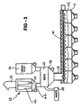
- Figure 3 is a detailed side view of the fluxing apparatus;
- Figure 4 is a perspective view of the fluxing apparatus; and
- Figure 5 is a perspective view of the fluxing apparatus taken along line 5 - 5 of Figure 1A.
- Referring to the Figures, wherein like numerals indicate like or corresponding parts throughout the several views, a fluxing apparatus, or fluxer, is generally disclosed at 10. The
fluxing apparatus 10 applies powdered flux 11 to anobject 12, such as aheat exchanger 12 for a vehicle. Although thefluxing apparatus 10 can be used to apply powdered flux 11 to anyobject 12, its most preferred application is in the manufacture ofheat exchangers 12. Accordingly, for descriptive purposes only, theobject 12 is hereinafter referred to as theheat exchanger 12. Furthermore, as disclosed in the Figures, thefluxing apparatus 10 is preferably utilized in a continuous method. In such a method, thefluxing apparatus 10 continuously applies powdered flux 11 to a plurality ofheat exchangers 12 that continuously traverse, or pass-through, thefluxing apparatus 10. Although thefluxing apparatus 10 applies powdered flux 11 to a plurality ofheat exchangers 12, the subject invention is primarily described below in terms of asingle heat exchanger 12. - The
fluxing apparatus 10 includes anenclosure 14, aconveyor 16, asupply hopper 18, at least oneapplication device 20, and aflux recovery system 22. These components are described additionally below. As understood by those skilled in the art, thefluxing apparatus 10 is utilized in combination with a core stacking machine, a thermal degreasing unit, and a brazing furnace to manufacture theheat exchanger 12. The core stacking machine, thermal degreasing unit, and brazing furnace are not pertinent to the subject invention. Accordingly, these components are not disclosed in the Figures. - The
fluxing apparatus 10 includes theenclosure 14. Theenclosure 14 includes aninlet 24 and anoutlet 26 and defines afluxing chamber 28. Theinlet 24 of theenclosure 14 receives theheat exchanger 12 into thefluxing chamber 28 prior to application of the powdered flux 11, and theheat exchanger 12 is discharged from theoutlet 26 of theenclosure 14 after the powdered flux 11 has been applied to theheat exchanger 12 by theapplication device 20 as described below. - The
fluxing apparatus 10 also includes theconveyor 16 that extends through theenclosure 14 through the between theinlet 24 and theoutlet 26. Theconveyor 16 traverses theobject 12 into and out of thefluxing chamber 28. Theheat exchanger 12 is mounted onto theconveyor 16 at or near theinlet 24 of theenclosure 14. Once on theconveyor 16, theheat exchanger 12 moves into theenclosure 14, into thefluxing chamber 28 where it is fluxed, and out of theenclosure 14 where theheat exchanger 12 then moves into the brazing furnace. Preferably, theconveyor 16 is continuous such that theheat exchanger 12 moves through theenclosure 14 at a constant rate. However, although it is not preferred, theconveyor 16 may be intermittent such that theheat exchanger 12 is moved into theenclosure 14, stops in thefluxing chamber 28 to be fluxed, and then moves out of theenclosure 14 and into the brazing furnace. - The type of
conveyor 16 that may be utilized includes, but is not limited to, a belt-type conveyor, a rod belt-type conveyor, or a roller-type conveyor. Although theconveyor 16 may be a single, continuous unit, it is preferred that theconveyor 16 includes a plurality ofconveyor sections 16A, 16B. In this preferred embodiment, at least one of theconveyor sections 16A is spaced from an adjacent conveyor section 16B to define an application gap 30 between theadjacent conveyor sections 16A, 16B. An underside of theheat exchanger 12 is, therefore, at least partially exposed at some point within thefluxing chamber 28. The importance of this partial exposure of the underside is described below. - The
fluxing apparatus 10 preferably includes anobject recognition system 32 that is disposed adjacent theinlet 24 of theenclosure 14. Theobject recognition system 32 detects at least one dimension of theheat exchanger 12 before the powdered flux 11 is to be applied to theheat exchanger 12. Preferably, theobject recognition system 32 detects the length, width, and depth of theheat exchanger 12. Theobject recognition system 32 more specifically includes at least onelaser 34 that detects the dimension or dimensions of theheat exchanger 12 prior to application of the powdered flux 11. Although not required, it is preferred that theobject recognition system 32 includes threelasers 34. Thelasers 34 detect the length, width, and depth of theheat exchanger 12 orheat exchangers 12 that are traversing into thefluxing chamber 28. Other devices suitable for detecting dimensions of objects, that are not necessarily laser-dependent, may be used as theobject recognition system 32 including, but not limited to, LED light curtains, photo-electric sensors, and video camera based vision systems. - The
fluxing apparatus 10 includes thesupply hopper 18. Thesupply hopper 18 stores the powdered flux 11 for delivery to theapplication device 20. Thesupply hopper 18 receives the powdered flux 11 from avirgin drum 36 of the powdered flux 11 or from excess powdered flux 11 that is recovered and recycled as described below. Regardless of its source, once the powdered flux 11 is in thesupply hopper 18, it is distributed toapplication device 20 to be applied to theheat exchanger 12. The fluxing apparatus includes afeed mechanism 38, preferably ascrew feeder 40, disposed between thesupply hopper 18 and theapplication device 20 for appropriately distributing the powdered flux 11 from thesupply hopper 18 to theapplication device 20. Thefeed mechanism 38, preferably thescrew feeder 40, is disposed in asupply bin 42 above theapplication device 20 to distribute the powdered flux 11 from thesupply hopper 18, through thesupply bin 42, and to theapplication device 20. It is to be understood that, although thefeed mechanism 38 is disclosed as thescrew feeder 40, thefeed mechanism 38 can be other equivalent devices that are suitable for distributing, i.e., moving, powdered materials, such as powdered flux 11. - As described above, the
fluxing apparatus 10 includes the at least oneapplication device 20, i.e., applicator. The at least oneapplication device 20 is in fluid communication with thesupply hopper 18 and is positioned to face at least one side of theconveyor 16 for applying the powdered flux 11 to theheat exchanger 12, which is on theconveyor 16. Theapplication device 20 may be a rotary atomizer, such as a bell, or may be a spray gun. - Although only one
application device 20 is required, the preferred embodiment includes a plurality ofspray guns 44 for applying the powdered flux 11 to theheat exchanger 12. Accordingly, the fluxing apparatus is primarily described having of the plurality ofspray guns 44. In the preferred embodiment, theapplication device 20 is an electrostatic spray application device, most preferablyelectrostatic spray guns 44. However, there is no requirement that theapplication device 20 be an electrostatic spray application device. Instead, for example, theapplication device 20 may be a non-electrostatic spray gun. - If the
application device 20 is an electrostatic spray application device, then it is understood by persons skilled in the art that additional hardware including, but not limited to, anti-static brushes, rubber wipers, and air blast devices, may be utilized to optimize the electrical continuity between theheat exchanger 12 and theconveyor 16 such that theheat exchanger 12 is sufficiently grounded and a uniform coating of flux on theheat exchanger 12 can be achieved. - At least one
reciprocation assembly 46 is disposed between thesupply hopper 18 and thespray guns 44. In this position, thereciprocation assembly 46 supports thespray guns 44 such that thespray guns 44 can reciprocate, i.e., move alternately back and forth, if necessary, during application of the powdered flux 11 to theobject 12. - Preferably, at least one
spray gun 44A of theplurality 44 is positioned to face a top side of theconveyor 16. As such, thisspray gun 44A applies the powdered flux 11 to a top side of theheat exchanger 12. It is also preferred that at least one spray gun 44B of theplurality 44 is positioned to face an underside of theconveyor 16 for applying the powdered flux 11 to the underside of theheat exchanger 12. More specifically, this particular spray gun 44B, i.e., the spray gun that faces the underside of theconveyor 16 applies the powdered flux 11 to the underside of theheat exchanger 12 through the application gap 30 defined between theadjacent conveyor sections 16A, 16B as described above. - In the most preferred embodiment, the plurality of
spray guns 44 is further defined as a first and second spray gun positioned to face the underside of theconveyor 16, and a third, fourth, fifth, and sixth spray gun positioned to face the top side of theconveyor 16. In this embodiment, there is afirst reciprocation assembly 46A, asecond reciprocation assembly 46B, a third reciprocation assembly 46C, and a fourth reciprocation assembly 46D. As disclosed best in the top view of Figure 2, thefirst reciprocation assembly 46A supports the first and second spray guns, thesecond reciprocation assembly 46B supports the third and fourth spray guns, the third reciprocation assembly 46C supports the fifth spray gun, and the fourth reciprocation assembly 46D supports the sixth spray gun. - The
feed mechanism 38, originally described above, is more specifically disposed between thesupply hopper 18 and thespray guns 44 for appropriately distributing the powdered flux 11 to each of thespray guns 44. To get to thespray guns 44, the powdered flux 11 is distributed from thesupply hopper 18, through thesupply bin 42 via thefeed mechanism 38, to thereciprocation assemblies 46, and then to thespray guns 44. A cone and venturi-type assembly 48 is disposed between thesupply bin 42 and thereciprocation assemblies 46, which support eachspray gun 44, to ensure that consistent and adequate amounts of the powdered flux 11 are supplied to each of thespray guns 44. Preferably, there is one cone and venturi-type assembly 48 associated with eachspray gun 44. - The
fluxing apparatus 10 further includes acontroller 50. Thecontroller 50, preferably a programmable logic controller (PLC), is operatively connected with theobject recognition system 32 described above and also with at least one of theconveyor 16 and theapplication device 20. Preferably, thecontroller 50 is operatively connected with theobject recognition system 32 and with both theconveyor 16 and theapplication device 20, i.e., thespray guns 44. It is to be understood that, if thecontroller 50 is operatively connected with thespray guns 44, then thecontroller 50 is operatively connected to thespray guns 44 through thereciprocation assemblies 46. That is, thecontroller 50 may also be operatively connected to thereciprocation assemblies 46. Due to such connections, thecontroller 50 is able to adjust an operating parameter of thefluxing apparatus 10 in response to the dimension, or dimensions, detected by theobject recognition system 32. In operation, theobject recognition system 32, preferably thelasers 34, reads the dimension or dimensions of theheat exchanger 12, and thecontroller 50 adjusts certain operating parameters including, but not limited to, conveyor speed, reciprocation speed, and reciprocation traverse length, i.e., the length of the stroke as thespray guns 44 traverse back and forth on areciprocation assembly 46. Adjustment of these, and other, operating parameters permits thefluxing apparatus 10 to adjust for and to therefore accommodatedifferent heat exchangers 12, i.e.,heat exchangers 12 having varying shapes and sizes. - The
fluxing apparatus 10 further incorporates a flow rate verification system for confirming that there is a flow of the powdered flux from theapplication device 20 to theheat exchanger 12. The flow rate verification system is incorporated into thecontroller 50 or some other controller operatively connected with thefluxing apparatus 10 and is utilized in embodiments where theapplication device 20 is an electrostatic spray application device. In such embodiments, an electric field is generated between theapplication device 20 and theheat exchanger 12. The flow rate verification system measures the current present in this electric field. In the absence of the powdered flux, the current of this electric field increases, and the flow rate verification system detects this increase and generates an alarm. More specifically, the flow rate verification system detects when the current exceeds a certain acceptable threshold and then generates the alarm. Thefluxing apparatus 10 automatically shuts down, or is manually shut down, in response to this alarm. - The
fluxing apparatus 10 further includes theflux recovery system 22. Theflux recovery system 22 is in fluid communication with thefluxing chamber 28 to introduce and to maintain a negative pressure within thefluxing chamber 28. As a result, any excess powdered flux 11 is retained within theenclosure 14. Excess powdered flux 11 is commonly referred to as overspray and is any powdered flux 11 within thefluxing chamber 28 that does not get applied to theheat exchanger 12. Also as a result of the negative pressure, the excess powdered flux 11 can be recovered and recycled to supplyhopper 18 as described below. - To retain the excess powdered flux 11 within the
enclosure 14 and to recover and subsequently recycle the excess powdered flux 11, theflux recovery system 22 includes aduct 52 that is in fluid communication with thefluxing chamber 28. The negative pressure is introduced and maintained within thefluxing chamber 28. More specifically, anexhaust fan 54 is in fluid communication with theduct 52. Thefan 54, which preferably operates on a continuous basis, introduces and maintains the negative pressure within thefluxing chamber 28 through theduct 52. Thefan 54 is represented schematically in Figure 4. - In addition to the
fluxing chamber 28, theduct 52 is also in fluid communication with thesupply hopper 18. As such, theduct 52 recycles the excess powdered flux 11 that has been recovered from thefluxing chamber 28 into thesupply hopper 18 as the negative pressure is maintained within thefluxing chamber 28. To recover the powdered flux 11 from thefluxing chamber 28, theflux recovery system 22 further includes at least onerecovery feed screw 56. Therecovery feed screw 56 is disposed within theflux chamber 28 adjacent a bottom of theflux chamber 28. Therecovery feed screw 56 is in fluid communication with theduct 52 for directing the excess powdered flux 11 into theduct 52 where the excess powdered flux 11 can then be recycled into thesupply hopper 18. Preferably, theflux recovery system 22 includes a plurality of recovery feed screws 56 to direct the excess powdered flux 11 into theduct 52. As disclosed in the Figures, the most preferred embodiment includes four recovery feed screws 56. In embodiments where there is more than onerecovery feed screw 56, theflux recovery system 22 further includes acollection manifold 58. Thecollection manifold 58 is represented schematically in Figures 1A, 2, and 4. Thecollection manifold 58 is disposed between the recovery feed screws 56 and theduct 52 for collecting the excess powdered flux 11 that has been recovered from each of the recovery feed screws 56 prior to recycling into thesupply hopper 18. Thecollection manifold 58 is in fluid communication with theduct 52 via a plurality of secondary ducts 60 that are associated with eachrecovery feed screw 56. Although a plurality of these secondary ducts 60 are disclosed in the Figures, only one secondary duct 60 (see Figure 2) is numbered for clarification purposes in the Figures. - The purpose of the
duct 52 is two-fold. First, air is drawn from thefluxing chamber 28 thereby establishing negative pressure within thechamber 28 to discourage the random floating of the powdered flux 11 out either theinlet 24 oroutlet 26 of theenclosure 14. Second, the excess powdered flux 11 is carried with the air that is drawn from thefluxing chamber 28 through theduct 52. Theflux recovery system 22 includes afilter 62 that is disposed between theduct 52 and thesupply hopper 18 for filtering the excess powdered flux 11 before is it recycled into thesupply hopper 18. More specifically, the excess powdered flux 11 collects on thefilter 52 as a retentate. A vibratingmechanism 64 vibrates thefilter 62 to recover this filter retentate. The recovered flux 11 is then introduced into asieve 66, where it is combined with the powdered flux 11 from thevirgin drum 36, then introduced into thesupply hopper 18, and then introduced into thesupply bin 42 via thefeed mechanism 38. Waste flux is collected in awaste bin 68. - The
fluxing apparatus 10 is applicable regardless-of whether theheat exchanger 12 is first processed through a thermal degreasing unit or not. Accordingly, thefluxing apparatus 10 may be utilized in the method described inUnited States Patent No. 6,036,083 which is entitled "Method For Braze Flux Application". - The invention has been described in an illustrative manner, and it is to be understood that the terminology which has been used is intended to be in the nature of words of description rather than of limitation.
- Obviously, many modifications and variations of the present invention are possible in light of the above teachings. It is, therefore, to be understood that within the scope of the appended claims, the invention may be practiced otherwise than as specifically described.
Claims (21)
- The use of a fluxing apparatus (10) for applying powdered flux (11) to an object (12), said apparatus comprising: an enclosure (14) defining a fluxing chamber (28) and comprising an inlet (24) for receiving the object (12) into said fluxing chamber (28) prior to application of the powdered flux (11) and an outlet (26) for discharging the object (12) from said fluxing chamber (28) after the powdered flux (11) has been applied; a conveyor (16) extending through said enclosure (14) between said inlet (24) and said outlet (26) for traversing the object (12) into and out of said fluxing chamber (28); a supply hopper (18) for storing the powdered flux (11); at least one application device (20) in fluid communication with said supply hopper (18) and positioned to face at least one side of said conveyor (16) for applying the powdered flux (11) to the object (12); and
characterised in that the fluxing apparatus comprises a flux recovery system (22) in fluid communication with said fluxing chamber (28) to introduce and maintain a negative pressure within said fluxing chamber (28) for retaining excess powdered flux (11) within said enclosure (14) and for recovering and recycling the excess powdered flux (11) to said supply hopper (18). - The use of a fluxing apparatus (10) as set forth in claim 1 further comprising an object recognition system (32) disposed adjacent said inlet (24) of said enclosure (14) for detecting at least one dimension of the object (12) prior to application of the powdered flux (11).
- The use of a fluxing apparatus (10) as set forth in claim 2 wherein said object recognition system (32) comprises at least one laser (34) that detects the at least one dimension of the object (12) prior to application of the powdered flux (11).
- The use of a fluxing apparatus (10) as set forth in claim 2 further comprising a controller (50) operatively connected with said object recognition system (32) and with at least one of said conveyor (16) and said at least one application device (20) for adjusting an operating parameter in response to the dimension detected by said object recognition system (32).
- The use of a fluxing apparatus (10) as set forth in claim 1 wherein said at least one application device (20) is further defined as a plurality of spray guns (44) for applying the powdered flux (11) to the object (12).
- The use of a fluxing apparatus (10) as set forth in claim 1 wherein said at least one application device (20) is further defined as an electrostatic application device.
- The use of a fluxing apparatus (10) as set forth in claim 5 further comprising a feed mechanism (38) disposed between said supply hopper (18) and said spray guns (44) for appropriately distributing the powdered flux (11) to each of said spray guns (44).
- The use of a fluxing apparatus (10) as set forth in claim 7 wherein said feed mechanism (38) is further defined as a screw feeder.
- The use of a fluxing apparatus (10) as set forth in claim 5 further comprising at least one reciprocation assembly (46) disposed between said supply hopper (18) and said spray guns (44) to support said spray guns (44) such that said spray guns (44) can reciprocate during application of the powdered flux (11) to the object (12).
- The use of a fluxing apparatus (10) as set forth in claim 5 wherein at least one spray gun (44) of said plurality is positioned to face a top side of said conveyor (16) for applying the powdered flux (11) to a top side of the object (12).
- The use of a fluxing apparatus (10) as set forth in claim 10 wherein at least one spray gun (44B) of said plurality is positioned to face an underside of said conveyor (16) for applying the powdered flux (11) to an underside of the object (12).
- The use of a fluxing apparatus (10) as set forth in claim 11 wherein said conveyor (16) comprises a plurality of conveyor sections with at least one of said conveyor sections spaced from an adjacent conveyor section to define an application gap (30) between said adjacent conveyor sections such that the underside of the object (12) is at least partially exposed to said spray gun (44B) that is positioned to face said underside of said conveyor (16).
- The use of a fluxing apparatus (10) as set forth in claim 5 wherein said plurality of spray guns (44) is further defined as a first and second spray gun positioned to face an underside of said conveyor (16), and a third, fourth, fifth, and sixth spray gun positioned to face a top side of said conveyor (16).
- The use of a fluxing apparatus (10) as set forth in claim 13 further comprising a first reciprocation assembly (46A) supporting said first and second spray guns (44), a second reciprocation assembly (46B) supporting said third and fourth spray guns (44), a third reciprocation assembly (46C) supporting said fifth spray gun, and a fourth reciprocation assembly (46D) supporting said sixth spray gun.
- The use of a fluxing apparatus (10) as set forth in claim 1 wherein said flux recovery system (22) comprises a duct (52) in fluid communication with said fluxing chamber (28) for introducing and maintaining the negative pressure within said fluxing chamber(28).
- The use of a fluxing apparatus (10) as set forth in claim 15 wherein said duct (52) is also in fluid communication with said supply hopper (18) for recycling the excess powdered flux (11) that has been recovered from said fluxing chamber (28) into said supply hopper (18) as the negative pressure is maintained within said fluxing chamber (28).
- The use of a fluxing apparatus (10) as set forth in claim 16 wherein said flux recovery system (22) further comprises a filter (62) disposed between said duct (52) and said supply hopper (18) for filtering the excess powdered flux (11) before is it recycled into said supply hopper (18).
- The use of a fluxing apparatus (10) as set forth in claim 16 wherein said flux recovery system (22) further comprises at least one recovery feed screw (56) disposed within said flux chamber (28) and in fluid communication with said duct (52) for directing the excess powdered flux (11) into said duct (52).
- The use of a fluxing apparatus (10) as set forth in claim 18 wherein said at least one recovery feed screw (56) is further defined as a plurality of recovery feed screws (56).
- The use of a fluxing apparatus (10) as set forth in claim 19 wherein said flux recovery system (22) comprises a collection manifold (58) disposed between said plurality of recovery feed screws (56) and said duct (52) for collecting the excess powdered flux (11) that has been recovered from each of said recovery feed screws (56) prior to recycling into said supply hopper(18).
- The use of a fluxing apparatus (10) as set forth in claim 15 wherein said flux recovery system (22) further comprises an exhaust fan (54) in fluid communication with said duct (52) for introducing and maintaining the negative pressure within said fluxing chamber (28) through said duct (52).
Applications Claiming Priority (5)
| Application Number | Priority Date | Filing Date | Title |
|---|---|---|---|
| US266561 | 1994-06-28 | ||
| US39037602P | 2002-06-21 | 2002-06-21 | |
| US390376P | 2002-06-21 | ||
| US10/266,561 US6755339B2 (en) | 2002-06-21 | 2002-10-08 | Fluxing apparatus for applying powdered flux |
| PCT/US2003/018656 WO2004000497A1 (en) | 2002-06-21 | 2003-06-13 | Fluxing apparatus for applying powdered flux |
Publications (2)
| Publication Number | Publication Date |
|---|---|
| EP1521660A1 EP1521660A1 (en) | 2005-04-13 |
| EP1521660B1 true EP1521660B1 (en) | 2008-01-30 |
Family
ID=29739208
Family Applications (1)
| Application Number | Title | Priority Date | Filing Date |
|---|---|---|---|
| EP03761061A Expired - Lifetime EP1521660B1 (en) | 2002-06-21 | 2003-06-13 | Use of a fluxing apparatus for applying powdered flux |
Country Status (5)
| Country | Link |
|---|---|
| US (1) | US6755339B2 (en) |
| EP (1) | EP1521660B1 (en) |
| AT (1) | ATE385210T1 (en) |
| DE (1) | DE60318947T2 (en) |
| WO (1) | WO2004000497A1 (en) |
Cited By (3)
| Publication number | Priority date | Publication date | Assignee | Title |
|---|---|---|---|---|
| CN106925454A (en) * | 2017-04-06 | 2017-07-07 | 天长市金陵电子有限责任公司 | A kind of high efficiency workpiece surface electrostatic powder coating machine |
| CN108940629A (en) * | 2018-07-13 | 2018-12-07 | 武汉理工大学 | Electrostatic spraying process device for fine blanking machine |
| CN110917752A (en) * | 2019-12-13 | 2020-03-27 | 扬州鑫科环保成套设备有限公司 | Powder spraying and pre-coating process for filter bag of spray paint waste gas filter |
Families Citing this family (36)
| Publication number | Priority date | Publication date | Assignee | Title |
|---|---|---|---|---|
| ITMI20040232A1 (en) * | 2004-02-12 | 2004-05-12 | Forni Tecnica S R L | METAL BRAZING PLANT |
| EP1978032A3 (en) † | 2004-07-22 | 2009-02-18 | Erasmus University Medical Center Rotterdam | Binding molecules |
| ITTO20050260A1 (en) * | 2005-04-18 | 2006-10-19 | R E A S N C Di Sassi E Baudin | PLANT, TUNNEL, DEVICE AND METHOD FOR WASHING OBJECTS WITH STEAM |
| EP1757373B1 (en) * | 2005-08-24 | 2012-04-11 | Brother Kogyo Kabushiki Kaisha | Film forming apparatus, film forming method and method for manufacturing piezoelectric actuator |
| WO2008064251A2 (en) * | 2006-11-22 | 2008-05-29 | Johnson Controls Technology Company | Space-saving multichannel heat exchanger |
| US8166776B2 (en) * | 2007-07-27 | 2012-05-01 | Johnson Controls Technology Company | Multichannel heat exchanger |
| GB0716696D0 (en) * | 2007-08-28 | 2007-10-03 | Pillarhouse Int Ltd | Fluxer for soldering apparatus |
| ITVI20080040A1 (en) * | 2008-02-14 | 2009-08-15 | Ge Ma Ta Spa | MACHINE FOR PAINTING OR COLORING PRODUCTS WITH EXTENDED SURFACES |
| DE102008010189B4 (en) | 2008-02-20 | 2018-05-09 | Dürr Systems Ag | Apparatus and method for separating wet paint overspray |
| DE102008015834A1 (en) * | 2008-03-27 | 2009-10-01 | Inos Automationssoftware Gmbh | Method and device for the automatic introduction or application of viscous material |
| CA2747285C (en) | 2008-12-19 | 2014-02-18 | Durr Systems Gmbh | Paint shop and method of operating a paint shop |
| US9085043B2 (en) | 2009-07-16 | 2015-07-21 | Lincoln Global, Inc. | Submerged arc welding system with pressurized flux delivery and welding torch |
| US8552329B2 (en) | 2009-07-16 | 2013-10-08 | Lincoln Global, Inc | Submerged arc welding system with pressurized flux delivery and welding torch |
| CN101934410B (en) * | 2010-08-25 | 2012-08-22 | 盐城市康杰机械制造有限公司 | Water tank core body main slice spraying device on aluminum soldering furnace |
| DE102014201014A1 (en) * | 2014-01-21 | 2015-07-23 | MAHLE Behr GmbH & Co. KG | Method for applying a flux |
| US9505017B2 (en) * | 2014-08-04 | 2016-11-29 | GM Global Technology Operations LLC | Rotary paint atomizer system and method of monitoring a rotary paint atomizer |
| US9994732B1 (en) | 2014-09-12 | 2018-06-12 | Steven Martin Johnson | Polysilazane and fluoroacrylate coating composition |
| US10562065B1 (en) | 2015-11-03 | 2020-02-18 | Newtech Llc | Systems and methods for application of polysilazane and fluoroacrylate coating compositions |
| WO2017116560A1 (en) * | 2015-12-29 | 2017-07-06 | Florida Cirtech, Inc. | System and method for application of coating compositions |
| US10584264B1 (en) | 2016-02-25 | 2020-03-10 | Newtech Llc | Hydrophobic and oleophobic coating compositions |
| CN106001839B (en) * | 2016-07-14 | 2018-05-04 | 深圳市新迪精密科技有限公司 | A kind of ventilation type scaling powder recovery system and its recovery method |
| EP3459642B1 (en) * | 2017-09-26 | 2020-08-05 | Wagner International Ag | Powder coating assembly for coating a workpiece with coating powder |
| CN107803566A (en) * | 2017-11-27 | 2018-03-16 | 江苏龙禾轻型材料有限公司 | Brazing flux spray equipment and its application method |
| US10939600B2 (en) * | 2018-11-28 | 2021-03-02 | International Business Machines Corporation | Flux residue detection |
| CN109290655A (en) * | 2018-12-03 | 2019-02-01 | 王伟华 | A kind of integrated circuit processing assembling equipment |
| CN109551077B (en) * | 2018-12-31 | 2024-05-14 | 佛山市泓实机械制造有限公司 | Automatic constant liquid level generating device without oxidized flux and using method thereof |
| CN110252542A (en) * | 2019-05-30 | 2019-09-20 | 安徽宏远机械制造有限公司 | A kind of machine components automatic spray apparatus |
| CN112221802A (en) * | 2020-08-31 | 2021-01-15 | 安徽蓝德正华电子有限公司 | Spraying device is used in processing of switch board special-shaped shell spare |
| DE102020134087A1 (en) | 2020-12-18 | 2022-06-23 | Gema Switzerland Gmbh | PLANT FOR COATING OBJECTS WITH COATING MATERIAL AND METHOD FOR COATING OBJECTS WITH COATING MATERIAL |
| DE102021207220A1 (en) * | 2021-07-08 | 2023-01-12 | Dürr Systems Ag | Treatment plant and method for treating workpieces |
| DE102021207218A1 (en) * | 2021-07-08 | 2023-01-12 | Dürr Systems Ag | Treatment plant and method for treating workpieces |
| CN113828444B (en) * | 2021-09-21 | 2023-07-18 | 东莞市兴帆机械有限公司 | Plastic spraying process for television backboard |
| DE102022119668A1 (en) * | 2022-08-04 | 2024-02-15 | Gema Switzerland Gmbh | ARRANGEMENT AND METHOD FOR PREFERABLY AUTOMATICALLY COATING OBJECTS |
| CN115957915A (en) * | 2023-02-07 | 2023-04-14 | 福建国顿泵业科技有限公司 | Spraying machine with oil paint liquid collecting effect for water pump production |
| CN115922081B (en) * | 2023-02-16 | 2023-05-26 | 成都金典牙科技术开发有限公司 | Band ring welding device |
| KR102853994B1 (en) * | 2023-03-08 | 2025-09-03 | (주)달성 | Submerged Arc Welding Equipment Of Belt Conveyer Pulley |
Citations (2)
| Publication number | Priority date | Publication date | Assignee | Title |
|---|---|---|---|---|
| US4901907A (en) * | 1987-02-27 | 1990-02-20 | Nihon Radiator Co. Ltd. | Heat exchanger core made of aluminum and method for application of flux during process of soldering thereof |
| US6036083A (en) * | 1998-01-26 | 2000-03-14 | General Motors Corporation | Method for braze flux application |
Family Cites Families (32)
| Publication number | Priority date | Publication date | Assignee | Title |
|---|---|---|---|---|
| US4009816A (en) * | 1975-09-02 | 1977-03-01 | Alpha Metals, Inc. | Method and apparatus for increasing efficiency of a foam fluxer used in wave soldering of printed wiring boards |
| JPS54140372A (en) * | 1978-04-21 | 1979-10-31 | Taihei Chem | Electrostatic holding conveyor belt and electrostatic holding shifter that use said belt |
| US4221957A (en) * | 1979-03-01 | 1980-09-09 | Combustion Engineering, Inc. | Welding flux closed loop system |
| US4342897A (en) * | 1980-01-28 | 1982-08-03 | Kobe Steel, Limited | Recovery type flux feeding assembly |
| US4348574A (en) * | 1980-06-13 | 1982-09-07 | Combustion Engineering, Inc. | Flux dam for submerged arc welding |
| DE3403541A1 (en) * | 1984-02-02 | 1985-08-08 | Deutsche Gesellschaft für Wiederaufarbeitung von Kernbrennstoffen mbH, 3000 Hannover | METHOD AND DEVICE FOR AUTOMATICALLY AND / OR REMOTELY WELDING THE LID AND / OR THE FLOOR WITH THE SHEATH OF CONTAINERS FOR THE RECEIVING OF RADIOACTIVE FUEL ELEMENTS AND HARDENING |
| US4561380A (en) | 1984-06-21 | 1985-12-31 | Nordson Corporation | Method and apparatus for powder coating a moving web |
| JPS62140677A (en) * | 1985-12-13 | 1987-06-24 | Taiheiyo Kiko Kk | Coating method for granular particle |
| US4770344A (en) | 1986-12-08 | 1988-09-13 | Nordson Corporation | Powder spraying system |
| US4989775A (en) * | 1987-12-15 | 1991-02-05 | Showa Aluminum Kabushiki Kaisha | Method for brazing aluminum components |
| US4796558A (en) * | 1988-02-19 | 1989-01-10 | Electrovert Limited | Foam fluxer |
| CH679839A5 (en) * | 1988-07-01 | 1992-04-30 | Aspa Zuerich Ag | |
| JP2825949B2 (en) * | 1990-07-26 | 1998-11-18 | サンデン株式会社 | Brazing method |
| JPH0550015A (en) | 1991-08-09 | 1993-03-02 | Kobe Steel Ltd | Coating method |
| NO176484C (en) * | 1992-02-12 | 1995-04-12 | Norsk Hydro As | A flux adhesive aluminum based component and process for its manufacture |
| US5328084A (en) * | 1992-05-04 | 1994-07-12 | General Motors Corporation | Aluminum heat exchanger braze furnace |
| US5316863A (en) * | 1992-05-18 | 1994-05-31 | Alcan International Limited | Self-brazing aluminum laminated structure |
| US5454872A (en) | 1993-07-28 | 1995-10-03 | Nordson Corporation | System for controlling and utilizing finer powder particles in a powder coating operation |
| JPH0747314A (en) | 1993-08-04 | 1995-02-21 | Hitachi Zosen Corp | Automatic coating equipment for long steel materials |
| US5632331A (en) * | 1993-09-30 | 1997-05-27 | Sanden Corporation | Heat exchanger |
| NL9500426A (en) * | 1995-03-03 | 1996-10-01 | Soltec Bv | Fluid density meter. |
| JPH09164478A (en) * | 1995-12-12 | 1997-06-24 | Zexel Corp | Brazing method |
| US5611476C1 (en) * | 1996-01-18 | 2002-02-26 | Btu Int | Solder reflow convection furnace employing flux handling and gas densification systems |
| DE69702723T2 (en) * | 1996-02-05 | 2001-03-29 | Sanden Corp | Heat exchangers manufactured by brazing a preliminary assembly and method of manufacturing the same |
| US5806752A (en) * | 1996-12-04 | 1998-09-15 | Ford Global Technologies, Inc. | Manufacture of aluminum assemblies by open-air flame brazing |
| DE19738097C2 (en) | 1997-09-01 | 2000-01-27 | Wagner International Ag Altsta | Method for operating an electrostatic powder coating system and electrostatic powder coating system |
| DE19738142C1 (en) | 1997-09-01 | 1999-05-20 | Wagner Int | Electrostatic coating system and method for detecting and coating workpieces in an electrostatic coating system |
| DE19749042C1 (en) * | 1997-11-06 | 1999-02-25 | Solvay Fluor & Derivate | Soldering process that avoids waste water disposal into environment |
| US6203628B1 (en) * | 1998-08-20 | 2001-03-20 | Toyo Aluminium Kabushiki Kaisha | Flux compositions for brazing aluminum, their films and brazing method |
| US6120848A (en) * | 1998-11-17 | 2000-09-19 | Ford Motor Company | Method of making a braze sheet |
| JP2000244108A (en) * | 1999-02-22 | 2000-09-08 | Senju Metal Ind Co Ltd | Soldering of printed board, soldering equipment for printed board, and cooling equipment therefor |
| US6379465B1 (en) | 1999-09-17 | 2002-04-30 | Nordson Corporation | Coating system with centralized control panel and gun mapping |
-
2002
- 2002-10-08 US US10/266,561 patent/US6755339B2/en not_active Expired - Lifetime
-
2003
- 2003-06-13 DE DE60318947T patent/DE60318947T2/en not_active Expired - Lifetime
- 2003-06-13 WO PCT/US2003/018656 patent/WO2004000497A1/en not_active Ceased
- 2003-06-13 EP EP03761061A patent/EP1521660B1/en not_active Expired - Lifetime
- 2003-06-13 AT AT03761061T patent/ATE385210T1/en not_active IP Right Cessation
Patent Citations (2)
| Publication number | Priority date | Publication date | Assignee | Title |
|---|---|---|---|---|
| US4901907A (en) * | 1987-02-27 | 1990-02-20 | Nihon Radiator Co. Ltd. | Heat exchanger core made of aluminum and method for application of flux during process of soldering thereof |
| US6036083A (en) * | 1998-01-26 | 2000-03-14 | General Motors Corporation | Method for braze flux application |
Cited By (3)
| Publication number | Priority date | Publication date | Assignee | Title |
|---|---|---|---|---|
| CN106925454A (en) * | 2017-04-06 | 2017-07-07 | 天长市金陵电子有限责任公司 | A kind of high efficiency workpiece surface electrostatic powder coating machine |
| CN108940629A (en) * | 2018-07-13 | 2018-12-07 | 武汉理工大学 | Electrostatic spraying process device for fine blanking machine |
| CN110917752A (en) * | 2019-12-13 | 2020-03-27 | 扬州鑫科环保成套设备有限公司 | Powder spraying and pre-coating process for filter bag of spray paint waste gas filter |
Also Published As
| Publication number | Publication date |
|---|---|
| US20030234272A1 (en) | 2003-12-25 |
| WO2004000497A1 (en) | 2003-12-31 |
| ATE385210T1 (en) | 2008-02-15 |
| DE60318947T2 (en) | 2009-01-22 |
| DE60318947D1 (en) | 2008-03-20 |
| US6755339B2 (en) | 2004-06-29 |
| EP1521660A1 (en) | 2005-04-13 |
Similar Documents
| Publication | Publication Date | Title |
|---|---|---|
| US6755339B2 (en) | Fluxing apparatus for applying powdered flux | |
| US5725670A (en) | Apparatus for powder coating welded cans | |
| EP1007222B1 (en) | Improvements relating to powder spray coating | |
| JP3234597B2 (en) | Powder coating system | |
| KR960013924B1 (en) | Cabin for spray coating objects with powdered coating material | |
| US4898116A (en) | Powder coating booth | |
| JP2522695B2 (en) | Method for reducing ambient effects on powder coating and powder coating apparatus thereof | |
| CA1103101A (en) | Apparatus and method for electrostatically powderspraying, particularly of enamel | |
| KR100361416B1 (en) | Work Spray Coating Device | |
| US5906676A (en) | Ejector-augmented overspray reclaim system | |
| US4768533A (en) | Paint and varnish stripping system | |
| US6190456B1 (en) | Spacer spraying device | |
| CN100540149C (en) | Spray booth | |
| US20230372974A1 (en) | Powder sieving apparatus for powder coating system | |
| WO2024173791A1 (en) | Paint removal booth assembly including at least one laser ablation robot, and a method of removing paint build-up from a skid | |
| KR101806087B1 (en) | Inside corner form powder coating machine | |
| JPH11253855A (en) | Automotive painting booth | |
| EP3096591B1 (en) | Method and device for reducing an electrostatic charge during the machining, joining or coating of areas using vacuum suction blasting | |
| US11446684B2 (en) | Air-wash powder sieving apparatus for powder coating system | |
| EP1375009B1 (en) | Method and apparatus for applying a powdered resin to fasteners | |
| KR101510566B1 (en) | Powder Coating Apparatus | |
| US20240278356A1 (en) | Paint removal booth assembly including at least one laser ablation robot | |
| JP2026016684A (en) | Powder coating equipment | |
| CN116871963A (en) | A CNC machine tool dust removal device | |
| JPH05308709A (en) | Method and apparatus for applying electric wire release agent |
Legal Events
| Date | Code | Title | Description |
|---|---|---|---|
| PUAI | Public reference made under article 153(3) epc to a published international application that has entered the european phase |
Free format text: ORIGINAL CODE: 0009012 |
|
| 17P | Request for examination filed |
Effective date: 20050121 |
|
| AK | Designated contracting states |
Kind code of ref document: A1 Designated state(s): AT BE BG CH CY CZ DE DK EE ES FI FR GB GR HU IE IT LI LU MC NL PT RO SE SI SK TR |
|
| 17Q | First examination report despatched |
Effective date: 20051005 |
|
| GRAP | Despatch of communication of intention to grant a patent |
Free format text: ORIGINAL CODE: EPIDOSNIGR1 |
|
| RTI1 | Title (correction) |
Free format text: USE OF A FLUXING APPARATUS FOR APPLYING POWDERED FLUX |
|
| RIN1 | Information on inventor provided before grant (corrected) |
Inventor name: KEMBLE, GARY, ALLAN Inventor name: LAMOTHE, CHRISTIAN Inventor name: ROSEN, JOHN, STANLEY, JR. |
|
| GRAS | Grant fee paid |
Free format text: ORIGINAL CODE: EPIDOSNIGR3 |
|
| GRAA | (expected) grant |
Free format text: ORIGINAL CODE: 0009210 |
|
| AK | Designated contracting states |
Kind code of ref document: B1 Designated state(s): AT BE BG CH CY CZ DE DK EE ES FI FR GB GR HU IE IT LI LU MC NL PT RO SE SI SK TR |
|
| REG | Reference to a national code |
Ref country code: GB Ref legal event code: FG4D |
|
| REG | Reference to a national code |
Ref country code: CH Ref legal event code: EP |
|
| REG | Reference to a national code |
Ref country code: IE Ref legal event code: FG4D |
|
| REF | Corresponds to: |
Ref document number: 60318947 Country of ref document: DE Date of ref document: 20080320 Kind code of ref document: P |
|
| PG25 | Lapsed in a contracting state [announced via postgrant information from national office to epo] |
Ref country code: LI Free format text: LAPSE BECAUSE OF FAILURE TO SUBMIT A TRANSLATION OF THE DESCRIPTION OR TO PAY THE FEE WITHIN THE PRESCRIBED TIME-LIMIT Effective date: 20080130 Ref country code: FI Free format text: LAPSE BECAUSE OF FAILURE TO SUBMIT A TRANSLATION OF THE DESCRIPTION OR TO PAY THE FEE WITHIN THE PRESCRIBED TIME-LIMIT Effective date: 20080130 Ref country code: ES Free format text: LAPSE BECAUSE OF FAILURE TO SUBMIT A TRANSLATION OF THE DESCRIPTION OR TO PAY THE FEE WITHIN THE PRESCRIBED TIME-LIMIT Effective date: 20080511 Ref country code: CH Free format text: LAPSE BECAUSE OF FAILURE TO SUBMIT A TRANSLATION OF THE DESCRIPTION OR TO PAY THE FEE WITHIN THE PRESCRIBED TIME-LIMIT Effective date: 20080130 |
|
| ET | Fr: translation filed | ||
| NLV1 | Nl: lapsed or annulled due to failure to fulfill the requirements of art. 29p and 29m of the patents act | ||
| REG | Reference to a national code |
Ref country code: CH Ref legal event code: PL |
|
| PG25 | Lapsed in a contracting state [announced via postgrant information from national office to epo] |
Ref country code: AT Free format text: LAPSE BECAUSE OF FAILURE TO SUBMIT A TRANSLATION OF THE DESCRIPTION OR TO PAY THE FEE WITHIN THE PRESCRIBED TIME-LIMIT Effective date: 20080130 |
|
| PG25 | Lapsed in a contracting state [announced via postgrant information from national office to epo] |
Ref country code: SI Free format text: LAPSE BECAUSE OF FAILURE TO SUBMIT A TRANSLATION OF THE DESCRIPTION OR TO PAY THE FEE WITHIN THE PRESCRIBED TIME-LIMIT Effective date: 20080130 Ref country code: BE Free format text: LAPSE BECAUSE OF FAILURE TO SUBMIT A TRANSLATION OF THE DESCRIPTION OR TO PAY THE FEE WITHIN THE PRESCRIBED TIME-LIMIT Effective date: 20080130 Ref country code: PT Free format text: LAPSE BECAUSE OF FAILURE TO SUBMIT A TRANSLATION OF THE DESCRIPTION OR TO PAY THE FEE WITHIN THE PRESCRIBED TIME-LIMIT Effective date: 20080630 |
|
| PG25 | Lapsed in a contracting state [announced via postgrant information from national office to epo] |
Ref country code: SK Free format text: LAPSE BECAUSE OF FAILURE TO SUBMIT A TRANSLATION OF THE DESCRIPTION OR TO PAY THE FEE WITHIN THE PRESCRIBED TIME-LIMIT Effective date: 20080130 Ref country code: CZ Free format text: LAPSE BECAUSE OF FAILURE TO SUBMIT A TRANSLATION OF THE DESCRIPTION OR TO PAY THE FEE WITHIN THE PRESCRIBED TIME-LIMIT Effective date: 20080130 Ref country code: SE Free format text: LAPSE BECAUSE OF FAILURE TO SUBMIT A TRANSLATION OF THE DESCRIPTION OR TO PAY THE FEE WITHIN THE PRESCRIBED TIME-LIMIT Effective date: 20080430 Ref country code: NL Free format text: LAPSE BECAUSE OF FAILURE TO SUBMIT A TRANSLATION OF THE DESCRIPTION OR TO PAY THE FEE WITHIN THE PRESCRIBED TIME-LIMIT Effective date: 20080130 Ref country code: DK Free format text: LAPSE BECAUSE OF FAILURE TO SUBMIT A TRANSLATION OF THE DESCRIPTION OR TO PAY THE FEE WITHIN THE PRESCRIBED TIME-LIMIT Effective date: 20080130 |
|
| PG25 | Lapsed in a contracting state [announced via postgrant information from national office to epo] |
Ref country code: RO Free format text: LAPSE BECAUSE OF FAILURE TO SUBMIT A TRANSLATION OF THE DESCRIPTION OR TO PAY THE FEE WITHIN THE PRESCRIBED TIME-LIMIT Effective date: 20080130 |
|
| PLBE | No opposition filed within time limit |
Free format text: ORIGINAL CODE: 0009261 |
|
| STAA | Information on the status of an ep patent application or granted ep patent |
Free format text: STATUS: NO OPPOSITION FILED WITHIN TIME LIMIT |
|
| 26N | No opposition filed |
Effective date: 20081031 |
|
| PG25 | Lapsed in a contracting state [announced via postgrant information from national office to epo] |
Ref country code: MC Free format text: LAPSE BECAUSE OF NON-PAYMENT OF DUE FEES Effective date: 20080630 |
|
| PG25 | Lapsed in a contracting state [announced via postgrant information from national office to epo] |
Ref country code: IE Free format text: LAPSE BECAUSE OF NON-PAYMENT OF DUE FEES Effective date: 20080613 Ref country code: BG Free format text: LAPSE BECAUSE OF FAILURE TO SUBMIT A TRANSLATION OF THE DESCRIPTION OR TO PAY THE FEE WITHIN THE PRESCRIBED TIME-LIMIT Effective date: 20080430 Ref country code: EE Free format text: LAPSE BECAUSE OF FAILURE TO SUBMIT A TRANSLATION OF THE DESCRIPTION OR TO PAY THE FEE WITHIN THE PRESCRIBED TIME-LIMIT Effective date: 20080130 |
|
| PG25 | Lapsed in a contracting state [announced via postgrant information from national office to epo] |
Ref country code: CY Free format text: LAPSE BECAUSE OF FAILURE TO SUBMIT A TRANSLATION OF THE DESCRIPTION OR TO PAY THE FEE WITHIN THE PRESCRIBED TIME-LIMIT Effective date: 20080130 |
|
| PG25 | Lapsed in a contracting state [announced via postgrant information from national office to epo] |
Ref country code: IT Free format text: LAPSE BECAUSE OF FAILURE TO SUBMIT A TRANSLATION OF THE DESCRIPTION OR TO PAY THE FEE WITHIN THE PRESCRIBED TIME-LIMIT Effective date: 20080130 |
|
| PG25 | Lapsed in a contracting state [announced via postgrant information from national office to epo] |
Ref country code: HU Free format text: LAPSE BECAUSE OF FAILURE TO SUBMIT A TRANSLATION OF THE DESCRIPTION OR TO PAY THE FEE WITHIN THE PRESCRIBED TIME-LIMIT Effective date: 20080731 Ref country code: LU Free format text: LAPSE BECAUSE OF NON-PAYMENT OF DUE FEES Effective date: 20080613 |
|
| PG25 | Lapsed in a contracting state [announced via postgrant information from national office to epo] |
Ref country code: TR Free format text: LAPSE BECAUSE OF FAILURE TO SUBMIT A TRANSLATION OF THE DESCRIPTION OR TO PAY THE FEE WITHIN THE PRESCRIBED TIME-LIMIT Effective date: 20080130 |
|
| PG25 | Lapsed in a contracting state [announced via postgrant information from national office to epo] |
Ref country code: GR Free format text: LAPSE BECAUSE OF FAILURE TO SUBMIT A TRANSLATION OF THE DESCRIPTION OR TO PAY THE FEE WITHIN THE PRESCRIBED TIME-LIMIT Effective date: 20080501 |
|
| REG | Reference to a national code |
Ref country code: DE Ref legal event code: R082 Ref document number: 60318947 Country of ref document: DE Representative=s name: BRP RENAUD UND PARTNER MBB RECHTSANWAELTE PATE, DE Ref country code: DE Ref legal event code: R082 Ref document number: 60318947 Country of ref document: DE Representative=s name: BRP RENAUD UND PARTNER MBB, DE Ref country code: DE Ref legal event code: R081 Ref document number: 60318947 Country of ref document: DE Owner name: MAHLE INTERNATIONAL GMBH, DE Free format text: FORMER OWNER: DELPHI TECHNOLOGIES, INC., TROY, MICH., US |
|
| REG | Reference to a national code |
Ref country code: FR Ref legal event code: PLFP Year of fee payment: 14 |
|
| REG | Reference to a national code |
Ref country code: FR Ref legal event code: PLFP Year of fee payment: 15 |
|
| REG | Reference to a national code |
Ref country code: FR Ref legal event code: TP Owner name: MAHLE INTERNATIONAL GMBH, DE Effective date: 20180103 |
|
| REG | Reference to a national code |
Ref country code: FR Ref legal event code: PLFP Year of fee payment: 16 |
|
| PGFP | Annual fee paid to national office [announced via postgrant information from national office to epo] |
Ref country code: FR Payment date: 20180629 Year of fee payment: 16 |
|
| PGFP | Annual fee paid to national office [announced via postgrant information from national office to epo] |
Ref country code: GB Payment date: 20180629 Year of fee payment: 16 Ref country code: DE Payment date: 20180831 Year of fee payment: 16 |
|
| REG | Reference to a national code |
Ref country code: GB Ref legal event code: 732E Free format text: REGISTERED BETWEEN 20190207 AND 20190213 |
|
| REG | Reference to a national code |
Ref country code: DE Ref legal event code: R119 Ref document number: 60318947 Country of ref document: DE |
|
| GBPC | Gb: european patent ceased through non-payment of renewal fee |
Effective date: 20190613 |
|
| PG25 | Lapsed in a contracting state [announced via postgrant information from national office to epo] |
Ref country code: DE Free format text: LAPSE BECAUSE OF NON-PAYMENT OF DUE FEES Effective date: 20200101 Ref country code: GB Free format text: LAPSE BECAUSE OF NON-PAYMENT OF DUE FEES Effective date: 20190613 |
|
| PG25 | Lapsed in a contracting state [announced via postgrant information from national office to epo] |
Ref country code: FR Free format text: LAPSE BECAUSE OF NON-PAYMENT OF DUE FEES Effective date: 20190630 |